Table of Contents
Advertisement
Quick Links
www.ti.com
User's Guide
TPS36Q1EVM Voltage Supervisor User Guide
This user's guide describes the TPS36Q1EVM evaluation module (EVM). This guide contains the EVM
schematic, bill of materials (BOM), assembly drawing and top and bottom board layouts.
1
Trademarks..............................................................................................................................................................................2
2
Introduction.............................................................................................................................................................................3
Documentation......................................................................................................................................................4
3 Schematic, Bill of Materials, and Layout..............................................................................................................................
Schematic..................................................................................................................................................6
3.2 TPS36Q1EVM Bill of Materials..........................................................................................................................................
4 EVM Connectors...................................................................................................................................................................
Jumpers...................................................................................................................................................................10
Points...............................................................................................................................................................12
Operation....................................................................................................................................................14
)............................................................................................................................................................
5.2 RESET ............................................................................................................................................................................
5.3 Manual Reset (MR)..........................................................................................................................................................
5.4 SET0 and SET1...............................................................................................................................................................
(WD_EN).............................................................................................................................................14
(WDI)......................................................................................................................................................14
5.7 Watchdog Output (WDO).................................................................................................................................................
5.8
CRST................................................................................................................................................................................14
5.9
CWD.................................................................................................................................................................................15
6 EVM Performance Results...................................................................................................................................................
7 Revision History...................................................................................................................................................................
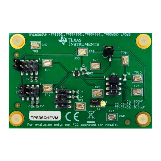
Figure 2-1. TPS36Q1EVM Board Top.........................................................................................................................................
Figure 3-1. TPS36Q1EVM Schematic.........................................................................................................................................
Figure 3-3. Component Placement-Bottom Assembly..............................................................................................................
Figure 3-4. Layout-Top..............................................................................................................................................................
Layout-Bottom.........................................................................................................................................................8
Layer...................................................................................................................................................................8
Figure 3-7. Bottom Layer.............................................................................................................................................................
Mask........................................................................................................................................................9
Figure 4-1. Schematic Closeup.................................................................................................................................................
Figure 6-1. Early Fault...............................................................................................................................................................
Figure 6-2. Late Fault................................................................................................................................................................
Pulse...............................................................................................................................................................17
Delay...........................................................................................................................................................17
Table 2-1. Voltage Supervisors....................................................................................................................................................
BOM............................................................................................................................................................................7
Table 4-2. Pinout B Onboard Jumpers.......................................................................................................................................
SLVUCG9 - OCTOBER 2022
Submit Document Feedback
ABSTRACT
Table of Contents
Placement....................................................................................................................................8
List of Figures
Bottom....................................................................................................................................3
Assembly....................................................................................................................8
List of Tables
Jumpers.......................................................................................................................................10
Copyright © 2022 Texas Instruments Incorporated
Table of Contents
TPS36Q1EVM Voltage Supervisor User Guide
5
7
10
14
14
14
14
14
16
17
3
6
8
8
8
13
16
16
3
11
1
Advertisement
Table of Contents

Related Manuals for Texas Instruments TPS36Q1EVM


Summary of Contents for Texas Instruments TPS36Q1EVM
-
Page 1: Table Of Contents
Table of Contents User’s Guide TPS36Q1EVM Voltage Supervisor User Guide ABSTRACT This user’s guide describes the TPS36Q1EVM evaluation module (EVM). This guide contains the EVM schematic, bill of materials (BOM), assembly drawing and top and bottom board layouts. Table of Contents Trademarks....................................2 Introduction.....................................3... -
Page 2: Trademarks
Table 4-4. Pinout D Onboard Jumpers (TPS35-Q1/TPS36-Q1 Only)..................12 Table 5-1. Typical t Values for TPS36-Q1 and TPS3436-Q1....................1 Trademarks All trademarks are the property of their respective owners. TPS36Q1EVM Voltage Supervisor User Guide SLVUCG9 – OCTOBER 2022 Submit Document Feedback Copyright © 2022 Texas Instruments Incorporated... -
Page 3: Introduction
Table 2-1 for specific functions supported by each family. The TPS36Q1EVM is shipped pre-installed with the TPS3436CCCBGDDFRQ1 device, but can be used with any TPS3435-Q1, TPS3436-Q1, TPS35-Q1, or TPS36-Q1 device variant. The TPS3435-Q1, TPS3436-Q1, TPS35-Q1, and TPS36-Q1 families offer multiple pinout options. The TPS36Q1EVM offers connections to all input and output pins supported by various pinouts. -
Page 4: Related Documentation
TPS3436-Q1 Automotive Nano IQ Precision Watchdog Timer data sheet TPS35-Q1 Automotive Nano IQ Precision Watchdog Timer data sheet TPS36-Q1 Automotive Nano IQ Precision Watchdog Timer data sheet TPS36Q1EVM Voltage Supervisor User Guide SLVUCG9 – OCTOBER 2022 Submit Document Feedback Copyright © 2022 Texas Instruments Incorporated... -
Page 5: Schematic, Bill Of Materials, And Layout
Schematic, Bill of Materials, and Layout 3 Schematic, Bill of Materials, and Layout This section provides a detailed description of the TPS36Q1EVM schematic, bill of materials (BOM), and layout. SLVUCG9 – OCTOBER 2022 TPS36Q1EVM Voltage Supervisor User Guide Submit Document Feedback... -
Page 6: Tps36Q1Evm Schematic
PIN4 5016 5016 PIN5 5016 SET0,SET1 PEC03SAAN PIN3 5016 CRST,WDI PIN2 15912080 CWD,MR,CRST,WD_EN 15912080 1µF 0.01µF 1µF 0.01µF Figure 3-1. TPS36Q1EVM Schematic TPS36Q1EVM Voltage Supervisor User Guide SLVUCG9 – OCTOBER 2022 Submit Document Feedback Copyright © 2022 Texas Instruments Incorporated... -
Page 7: Tps36Q1Evm Bill Of Materials
Schematic, Bill of Materials, and Layout 3.2 TPS36Q1EVM Bill of Materials Table 3-1. BOM PACKAGE DESIGNATOR QUANTITY VALUE DESCRIPTION PART NUMBER MANUFACTURER REFERENCE !PCB Printed Circuit Board LP064 0.1 µF CAP, CERM, 0.1 µF, 16 V, ± 5%, X7R, 0603... -
Page 8: Layout And Component Placement
Figure 3-2. Component Placement—Top Assembly Figure 3-3. Component Placement—Bottom Assembly Figure 3-5. Layout—Bottom Figure 3-4. Layout—Top Figure 3-6. Top Layer Figure 3-7. Bottom Layer TPS36Q1EVM Voltage Supervisor User Guide SLVUCG9 – OCTOBER 2022 Submit Document Feedback Copyright © 2022 Texas Instruments Incorporated... -
Page 9: Figure 3-8. Top Solder Mask
Schematic, Bill of Materials, and Layout Figure 3-8. Top Solder Mask SLVUCG9 – OCTOBER 2022 TPS36Q1EVM Voltage Supervisor User Guide Submit Document Feedback Copyright © 2022 Texas Instruments Incorporated... -
Page 10: Evm Connectors
Connect a shunt jumper to pins 1-2 to activate pull-up resistor R2 and pull the RESET output high. Disconnect pins 1-2 if using a push-pull variant. TPS36Q1EVM Voltage Supervisor User Guide SLVUCG9 – OCTOBER 2022 Submit Document Feedback Copyright © 2022 Texas Instruments Incorporated... -
Page 11: Table 4-2. Pinout B Onboard Jumpers
Connect a shunt jumper to pins 1-2 to activate pull-up resistor R2 and pull the RESET output high. Disconnect pins 1-2 if using a push-pull variant. SLVUCG9 – OCTOBER 2022 TPS36Q1EVM Voltage Supervisor User Guide Submit Document Feedback Copyright © 2022 Texas Instruments Incorporated... -
Page 12: Evm Test Points
5-6 of jumper J1 connects pin 1 to GND, a logic low. Pins can also be connected to delay capacitors via the jumpers, and these connections can be used to adjust programmable timeout periods. TPS36Q1EVM Voltage Supervisor User Guide SLVUCG9 – OCTOBER 2022 Submit Document Feedback Copyright ©... -
Page 13: Figure 4-1. Schematic Closeup
EVM Connectors Figure 4-1. Schematic Closeup SLVUCG9 – OCTOBER 2022 TPS36Q1EVM Voltage Supervisor User Guide Submit Document Feedback Copyright © 2022 Texas Instruments Incorporated... -
Page 14: Evm Setup And Operation
5 EVM Setup and Operation This section describes the functionality and operation of the TPS36Q1EVM. Even though this EVM comes with the TPS3436CCCBGDDFRQ1 variant, this section will cover the EVM utilization with the TPS36-Q1, TPS35-Q1, and TPS3435-Q1 installed on the board. All timing based parameters of this device are located in the respective device's datasheet. -
Page 15: Cwd
TPS3435-Q1 devices or the watchdog close window period t for TPS36-Q1 and TPS3436-Q1 devices. The TPS36Q1EVM offers two pre-installed options: 0.01µF and 1µ. These capacitors correspond to 49.5ms and 4.95s t time delays for the TPS35-Q1 and TPS3435-Q1 devices, respectively. The t values are determined by the SET0 and SET1 pins;... -
Page 16: Evm Performance Results
6 EVM Performance Results The following measurements are taken using the TPS3436CCCBGDDFRQ1 with SET0=0 and SET1=0. Figure 6-1. Early Fault Figure 6-2. Late Fault TPS36Q1EVM Voltage Supervisor User Guide SLVUCG9 – OCTOBER 2022 Submit Document Feedback Copyright © 2022 Texas Instruments Incorporated... -
Page 17: Revision History
Revision History Figure 6-3. Valid Pulse Figure 6-4. Startup Delay SLVUCG9 – OCTOBER 2022 TPS36Q1EVM Voltage Supervisor User Guide Submit Document Feedback Copyright © 2022 Texas Instruments Incorporated... - Page 18 NOTE: Page numbers for previous revisions may differ from page numbers in the current version. DATE REVISION NOTES October 2022 Initial Release TPS36Q1EVM Voltage Supervisor User Guide SLVUCG9 – OCTOBER 2022 Submit Document Feedback Copyright © 2022 Texas Instruments Incorporated...
- Page 19 STANDARD TERMS FOR EVALUATION MODULES Delivery: TI delivers TI evaluation boards, kits, or modules, including any accompanying demonstration software, components, and/or documentation which may be provided together or separately (collectively, an “EVM” or “EVMs”) to the User (“User”) in accordance with the terms set forth herein.
- Page 20 www.ti.com Regulatory Notices: 3.1 United States 3.1.1 Notice applicable to EVMs not FCC-Approved: FCC NOTICE: This kit is designed to allow product developers to evaluate electronic components, circuitry, or software associated with the kit to determine whether to incorporate such items in a finished product and software developers to write software applications for use with the end product.
- Page 21 www.ti.com Concernant les EVMs avec antennes détachables Conformément à la réglementation d'Industrie Canada, le présent émetteur radio peut fonctionner avec une antenne d'un type et d'un gain maximal (ou inférieur) approuvé pour l'émetteur par Industrie Canada. Dans le but de réduire les risques de brouillage radioélectrique à...
- Page 22 www.ti.com EVM Use Restrictions and Warnings: 4.1 EVMS ARE NOT FOR USE IN FUNCTIONAL SAFETY AND/OR SAFETY CRITICAL EVALUATIONS, INCLUDING BUT NOT LIMITED TO EVALUATIONS OF LIFE SUPPORT APPLICATIONS. 4.2 User must read and apply the user guide and other available documentation provided by TI regarding the EVM prior to handling or using the EVM, including without limitation any warning or restriction notices.
- Page 23 Notwithstanding the foregoing, any judgment may be enforced in any United States or foreign court, and TI may seek injunctive relief in any United States or foreign court. Mailing Address: Texas Instruments, Post Office Box 655303, Dallas, Texas 75265 Copyright © 2019, Texas Instruments Incorporated...
- Page 24 TI products. TI’s provision of these resources does not expand or otherwise alter TI’s applicable warranties or warranty disclaimers for TI products. TI objects to and rejects any additional or different terms you may have proposed. IMPORTANT NOTICE Mailing Address: Texas Instruments, Post Office Box 655303, Dallas, Texas 75265 Copyright © 2022, Texas Instruments Incorporated...
Need help?
Do you have a question about the TPS36Q1EVM and is the answer not in the manual?
Questions and answers