Table of Contents
Advertisement
Please direct all questions to your local VeEX
Or, contact VeEX technical support at www.veexinc.com.
No part of this user manual may be reproduced, translated into a foreign language, or
be transmitted electronically without prior agreement and written consent of VeEX
Incorporated as governed by International copyright laws. Information contained in this
manual is provided "as is" and is subject to change without notice. Trademarks of VeEX
Incorporated have been identified where applicable, however the absence of such
identification does not affect the legal status of any trademark.
Copyright 2020 VeEX Incorporated. All rights reserved.
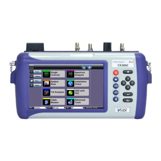
CX380C
CATV Maintenance Test Set
Sales Office, Representative, or Distributor.
®
USER MANUAL
D07-00-147P RevA00
Advertisement
Table of Contents

Subscribe to Our Youtube Channel
Related Manuals for VeEX CX380C


Summary of Contents for VeEX CX380C
- Page 1 VeEX Incorporated as governed by International copyright laws. Information contained in this manual is provided “as is” and is subject to change without notice. Trademarks of VeEX Incorporated have been identified where applicable, however the absence of such identification does not affect the legal status of any trademark.
-
Page 2: Table Of Contents
Table of Contents 1.0 General Information 1.1 Customer Support 1.2 Warranty 1.3 Patent Information 1.4 Documentation Conventions 2.0 Safety Information 3.0 Introduction to CX380C 3.1 Key Features 4.0 Basic Operation 4.1 Compact Platform Overview 4.2 Keypad 4.3 Touch Screen Display 4.4 Battery 4.5 Connectors and Panels... - Page 3 8.1.1 Sweep Limits 8.1.2 CaLan Master Profile 8.2 Run Sweep 8.2.1 Sweep Screen 8.2.2 Sweep Mode 8.2.3 Sweep Status and Sweep Table 8.3 Reference 8.4 Controls 8.4.1 Frequency Controls 8.4.2 Scale Controls CX380C User Manual RevA00 Page 3 of 105...
- Page 4 9.4 WiFi inSSIDer 9.5 OTDR Viewer 9.6 Ethernet Tools 9.7 HIP 9.8 TDR 9.9 In Service Sweep 9.10 R-Server 9.11 DMM 10.0 Tools 10.1 IP Tools 10.1.1 Setup 10.1.2 IP Connection Status 10.1.3 Ping CX380C User Manual RevA00 Page 4 of 105...
- Page 5 12.0 File Management 12.1 File Manager: Working with Saved Results, Profiles, Images 12.1.1 Backup and Restore Files 13.0 Setup - Main Menu 14.0 Certifications and Declarations 15.0 About VeEX Go back to top CX380C User Manual RevA00 Page 5 of 105...
-
Page 6: General Information
VeEX, Inc. or VeEX's licensors. The purchaser of this device and/or software, downloaded or embedded, agrees that it has received a license solely to use the software as embedded in the device and/or provided by VeEX Inc., and to use it solely as intended and described in this manual. -
Page 7: Patent Information
1.3 Patent Information VeEX product hardware and software may be protected by one or more patents on file with the United States Patent Office. Go back to top Go back to TOC 1.4 Documentation Conventions Icons used in this manual: Marks a helpful tip (action or method), which can save time and improve usability of the product. -
Page 8: Safety Information
Do not operate the instrument in the presence of flammable gases or fumes or any other combustible environment. VeEX Inc. assumes no liability for the customer's failure to comply with safety precautions and requirements. -
Page 9: Introduction To Cx380C
® The VeEX CX380c is a powerful CATV Maintenance test set featuring Forward and Return Path Sweep, DOCSIS 3.1 OFDM Analysis, Spectrum Analysis, Advanced QAM, and VeTest speedtest capabilities. For the most recent product specifications, see the product page on www.veexinc.com. -
Page 10: Basic Operation
(not used in Application dependent. OTDR). Returns to previous screen/function. Help: Accesses the User Manual. Lock/Unlock Touch Screen: Can also be programmed to capture screen shots (>Utilities>Settings>Global>Save Settings). CX380C User Manual RevA00 Page 10 of 105... -
Page 11: Touch Screen Display
Never use any sharp object such as a pen, screwdriver, or similar item. Clean the surface of the touch screen using a soft cloth and mild detergent only. Do not use alcohol. Go back to top Go back to TOC CX380C User Manual RevA00 Page 11 of 105... -
Page 12: Battery
4.4 Battery The CX380C chassis is equipped with an intelligent Li-ion rechargeable battery pack, which is located in the rear of the unit. The battery will be partially charged upon delivery, so it is recommended to fully charge the battery before use. Please charge the battery at room temperature to preserve its life and to obtain maximum charge. -
Page 13: Utility Ports
The following test ports are available on the CX380C: RF-IN: "F" Connector, 75 ohms for connection to the CATV network (maximum voltage input 100VAC) Provides access to: VeCheck, Signal Level Meter (SLM) and associated functions DOCSIS 3.1 Cable Modem and OFDM Analysis AUX: "F"... -
Page 14: Software Upgrade
USB stick formatted in the FAT-32 file format. 4. Power OFF the CX380C unit and verify that the AC adaptor connected to the unit is charging the battery. 5. Insert the USB stick into the port on the right side of the unit. -
Page 15: Home Screen And Menu
The function keys are application dependent. Bottom Panel: Tbl (Channel Table): Select a channel table to test. Loc (Location): Select Location threshold. TP (Test Point): Select test point compensation Date and Time CX380C User Manual RevA00 Page 15 of 105... -
Page 16: Screen Icons
QAM Unlocked: Indicates QAM Lock has not WiFi: Unit is connected to WiFi. been achieved on the digital carrier. QAM Lock is required to make Constellation measurements. Go back to top Go back to TOC CX380C User Manual RevA00 Page 16 of 105... -
Page 17: Setup
5. On the Channel Table Editor screen, make changes as required and press Save. To add this table to the existing list, type a new name for the table. For field descriptions, see Setup - Main Menu. CX380C User Manual RevA00 Page 17 of 105... - Page 18 Channel Table Selection: Main Menu Channel Table List CX380C User Manual RevA00 Page 18 of 105...
-
Page 19: Locations
Groundblock, Set Top Box and Tap locators. When performing a measurement, one of these preset locations can be selected by tapping the check box. Location Selection To edit measurement thresholds for the preset locations: CX380C User Manual RevA00 Page 19 of 105... - Page 20 5. Once new values have been entered, press Save or Save As and type a new name to save the new thresholds as a new Location. Location Editor - Analog Location Editor - Digital Go back to top Go back to TOC CX380C User Manual RevA00 Page 20 of 105...
-
Page 21: Test Point Compensation
Forward Comp (dB): Downstream related measurements, such as Single Channel, Installation Check, and Cable Modem Downstream Levels. Return Comp (dB): Cable Modem Upstream Transmit Levels. TP Editor Go back to top Go back to TOC CX380C User Manual RevA00 Page 21 of 105... -
Page 22: Test Applications
About 3 seconds after releasing the Arrow Up or Down key, the measurement will start. CX380C remembers the last channel measured, and upon entry, the last channel number will be used. - Page 23 Using sync pulses, the carrier is at its peak power and it does not change from scene-to-scene; therefore, peak power has become the standard for analog video carrier level measurements. The CX380C measures the peak level for analog carrier. Analog Carriers - Peak Power Measurement...
-
Page 24: Digital Channel Measurements
CSO-4 offset: -1.25MHz The CX380C first measures the signal levels at those frequency offsets of a live carrier then prompts to either use a channel blocker or remove the carrier. The same frequency offsets will be measured after the carrier is removed or blocked and they are used to compare with the previously measured results with a live carrier to determine the final CSO/CTB values. - Page 25 - this is often referred to as the "Cliff Effect". Ideally, there should be at least 4 to 5dB of margin from the MER where significant errors occur to allow for system degradation. MER measurements are useful for early detection of non-transient (noise) impairments, such as system noise Ingress. CX380C User Manual RevA00 Page 25 of 105...
-
Page 26: Constellation Measurements
The constellation display supports a zoom function. For QAM64 and QAM256 modulation, the constellation is split into 4 quadrants for simplified viewing. Tap on any of the four quadrants to zoom into this selected quadrant. CX380C User Manual RevA00 Page 26 of 105... - Page 27 (e.g. FEC) will attempt to the correct these errors, thus avoiding video impairments. Observing the symbol's shape and location relative to their ideal positions allows some conclusions about the nature of an impairment CX380C User Manual RevA00 Page 27 of 105...
- Page 28 IF equalizers and up/down converters. Gain Compression Broadband or system noise - Causes symbol clusters to enlarge, which increases the probability of errors. An error occurs when the dot is pulled across a decision boundary. CX380C User Manual RevA00 Page 28 of 105...
- Page 29 Phase jitter is a statistical quantity that affects the I and Q path equally. Phase noise causes the symbol clusters to appear as arcs, particularly those near the edges of the constellation. Phase noise can also result from faulty headend up/down converters. CX380C User Manual RevA00 Page 29 of 105...
-
Page 30: Impairment Measurements
Carrier to Ingress Carrier to noise HUM in % Phase jitter in degrees Symbol Rate Error in ppm Frequency Error in ppm (deviation from nominal preset frequency) Peak-to-Peak Frequency Response Peak-to-Peak Group Delay CX380C User Manual RevA00 Page 30 of 105... -
Page 31: Graph Mode
QAM carrier only as channel conditions change. This process maximizes or greatly improves the Modulation Error Ratio (MER) in the forward or reverse path. Impairment Graph (Adaptive Equalizer) CX380C User Manual RevA00 Page 31 of 105... -
Page 32: Timed Stats
It is important to know how hard the adaptive equalizer is working to determine if there is any margin for system degradation. To solve this problem, the CX380C adaptive equalizer can be turned off, allowing a technician to easily identify, sectionalize and locate these difficult linear type distortion problems. -
Page 33: Tilt Analysis
The CX380C measures up to 8 analog and 8 digital channels simultaneously. Normally, the tilt is measured from the lowest frequency channel to the highest frequency channel; however, any two channels can be selected to measure their tilt by tapping on the channel in the bar graph. -
Page 34: Spectrum Analysis
As the VCO sweeps through its frequency range, a trace is drawn across the screen. This trace shows the spectral content of the input signal within a selected range of frequencies. Go back to top Go back to TOC CX380C User Manual RevA00 Page 34 of 105... -
Page 35: Setup
Start Frequency (MHz) and Stop Frequency (MHz) The CX380C allows the entry of Start and Stop frequency in place of the CF and Span. The entry mode can be changed by tapping on the CF or START icon. The entry range is from 5MHz to 1000MHz. - Page 36 Dynamic Range CX380C has a dynamic range of 60dB with a display range of 70dB. If the received signal level is higher than the peak of the dynamic range, the RF receiver will be overdriven and results in unexpected spurious spikes on the spectrum display.
-
Page 37: Amplitude Measurements
Spectrum Analyzers typically do not have an IF or resolution bandwidth wide enough to measure a whole digital signal at once. To overcome this problem, the CX380C makes multiple measurements across the frequency range of the carrier. The powers of each of these measurements are summed up and the average power of the whole channel is calculated. -
Page 38: Ingress Measurements
2nd and 3rd order Intermodulation Distortion (IMD) products or beats. These beats will occur every 6, 7 or 8MHz in the reverse path, depending on the channel plan used. Although the magnitude of these beats is small, they increase at a node when several reverse paths are combined. CX380C User Manual RevA00 Page 38 of 105... -
Page 39: Cable Modem
CMTS, frequency agility, fixed-frame and variable- length PDU formats, Time-Division Multiple Access (TDMA), programmable Reed-Solomon FEC and preambles, and capability to support future physical layer technologies. CX380C User Manual RevA00 Page 39 of 105... -
Page 40: Setup
7.4.1 Setup The CX380C offers a built-in DOCSIS 3.1 cable modem as an option. The built-in cable modem is able to range, register and connect with the headend CMTS to obtain the necessary parameters and a valid IP address on the network. - Page 41 7. CM now forwards a bandwidth request to the CMTS, which in turn forwards a grant to the CM, permitting it to forward upstream information in allocated time slots. 8. CM now makes a DHCP discovery followed by a DHCP request. The CMTS forwards a DHCP acknowledgment from the CX380C User Manual RevA00 Page 41 of 105...
- Page 42 Go back to top Go back to TOC Server Connections DOCSIS specifies that for a system to become functional and operational, the CMTS and CM must interface with the following mandatory servers: CX380C User Manual RevA00 Page 42 of 105...
-
Page 43: Cable Modem Result - Docsis
Cable Modem - IP Results Go back to top Go back to TOC Link tab: Provides information about the packets received, the downstream signal (frequency, modulation, level, MER) and about the upstream signal (frequency, level, modulation). CX380C User Manual RevA00 Page 43 of 105... - Page 44 The Upstream channels provide Upstream Pre-Equalization information, which can be obtained by tapping on an Upstream UCD number. Press the Marker button to highlight a specific pre-equalizer coefficient, for advanced troubleshooting information. CX380C User Manual RevA00 Page 44 of 105...
- Page 45 2. Make appropriate selections for Provider and VeTest Server. If the selections cannot be found, press Update List to check for the latest VeTest Server List site. The Update List feature requires the Cable Modem to be online. 3. Press Start to begin the test. Cable Modem - VeTest Setup CX380C User Manual RevA00 Page 45 of 105...
- Page 46 Connect. Once the Cable Modem goes online, connect a PC to the meter's 10/100/1000T RJ45 port at the top of the unit. Traffic will pass through the meter, which functions like an actual cable modem. Cable Modem - Pass Through Go back to top Go back to TOC CX380C User Manual RevA00 Page 46 of 105...
- Page 47 1. For a system that contains both Single Carrier QAM (SC-QAM) and OFDM channels, enter the primary SC-QAM DOCSIS Channel number and press Connect to go online. Ranging tab, Online Status in D3.1 Mode CX380C User Manual RevA00 Page 47 of 105...
- Page 48 U CWE: Uncorrectable Codeword Errors 2. For a system that contains only OFDM channels, in the Setup tab, press OFDM Check. Enter the center frequency of the OFDM Phy Link Channel (PLC). Press Connect. CX380C User Manual RevA00 Page 48 of 105...
-
Page 49: Ofdm/Subcarriers
Update Scan: Reruns the scan for updated measurements. Power Scan: Runs power signal level scan. MER Scan: Runs MER measurement. Noise Floor: Measures noise. MER & Noise: Runs MER scan and displays noise. OFDM Subcarrier Power Scan CX380C User Manual RevA00 Page 49 of 105... - Page 50 OFDM Subcarrier Scan - MER OFDM Subcarrier Scan - Noise Floor CX380C User Manual RevA00 Page 50 of 105...
- Page 51 OFDM Subcarrier Scan - MER & Noise Go back to top Go back to TOC CX380C User Manual RevA00 Page 51 of 105...
- Page 52 Forward Path Sweeps verify the frequency response and proper operation of amplifiers to ensure proper tilt and balancing. The CX380C is fully compatible with the CaLan 3010H+ Headend Sweep Transmitter, which injects active sweep points, enabling a forward path sweep up to 1.8 GHz. Even with an all-digital HFC system, tone insertion between QAM channels is made possible by the CaLan 3010H+'s ability to transmit lower level sweep tones that do not impair live QAM channels.
-
Page 53: Sweep Settings
This function verifies the frequency response, tilt and proper operation of the amplifiers. CX380C works in conjunction with the CaLan 3010H+ Sweep System installed at the Headend, enabling a return path sweep up to 204 MHz. CX380C operates as a return path transmitter, injecting active sweep points. -
Page 54: Sweep Limits
4. After making changes, tap Save to save the changes to the existing Location or tap Save As to create a new Location. 5. Tap the Exit icon to return to the previous screen. Location Settings - Limits Screen CX380C User Manual RevA00 Page 54 of 105... -
Page 55: Calan Master Profile
8.1.2 CaLan Master Profile Set the CaLan Master Profile which contains the communications frequencies between the CaLan 3010H+ and the CX380C. In most cases, this profile will be previously configured on the CaLan 3010H+; however profiles can be edited or created by the unit. -
Page 56: Run Sweep
Communications: Two communication downstream frequency settings are required, one for the Forward Sweep and a second for the Return Sweep. The upstream communications for the CX380C to communicate back to the CaLan 3010H+ is set by the 3010H+ and sent to the CX380C on the downstream communications. No upstream communications frequency setup is required. - Page 57 Single Ch.: Tap to see the Single Channel SLM screen. See Single Channel Measurement for more information. Tap the Return button to view the Return Sweep Settings. See the above descriptions for field details. CX380C User Manual RevA00 Page 57 of 105...
-
Page 58: Sweep Screen
Sweep Screen To receive the communications signal the sweep input level to the CX380C must be at least -20 dBmV with the attenuation set to 0 dB. If Auto Attenuator is enabled on the Setup screen, the attenuation setting is set automatically when sweep is initialized. If communication is not established, go to the Scale screen and manually adjust the attenuation. -
Page 59: Sweep Mode
8.2.2 Sweep Mode Tap the Return button to switch to the Return Sweep mode. Similar to Forward Sweep, the test signal is generated by the CX380C, injected into the system, and measured by the CaLan 3010H+ at the headend of Hub. The results data is then sent back to the CX380C unit. -
Page 60: Reference
Note: Check the Automatically load selected reference file box at the bottom to initialize the sweep mode with the selected reference file automatically. Tap Live Only to display the current Sweep only. CX380C User Manual RevA00 Page 60 of 105... - Page 61 Tap Ref. Only to display only the saved Sweep that is loaded to use for comparison. Reference Sweep Mode - Reference Only View Tap Both to display both the saved Sweep that is loaded to use for comparison and the Live Sweep. CX380C User Manual RevA00 Page 61 of 105...
-
Page 62: Controls
Tap the small green left & right arrows at the top of the graph to "slide" the displayed frequency range up or down the spectrum. Frequency Controls CX380C User Manual RevA00 Page 62 of 105... -
Page 63: Scale Controls
Averaging is the number of sequential traces that are averaged for each trace. Check the Auto box (Automatic Gain & Slope Offset) to have the Gain and Slope Offset set automatically based on the Location Limits. The CX380C will compare the limits set for the current Location to the limits set for the location of the Reference File and then offset the test results by the appropriate Gain and Slope Offset. -
Page 64: Advanced Tools Menu
Clear images are displayed on the V300 products for immediate analysis and can be saved for record keeping. Fiber Scope CX380C User Manual RevA00 Page 64 of 105... -
Page 65: Automatic Focus Detection And Analysis
Instead of adding the extra complexity, fragility, cost, size and weight of other electromechanical focusing systems currently available in the market, VeEX’s auto focus detection technology still relies on the incredible fast response and finesse of human hands, but leaves the focus assessment, image capturing and analysis to the test set. A perfectly focused image of the connector end-face can be achieved in a few seconds even with eyes closed. -
Page 66: Fiber Connectors And Test Gear Vulnerabilities
Interchangeable tips – Most commonly used tips are available (FC, SC, LC, ST, MTP, E2000, including PC, APC, 60° angled tips, among others) Compatible with VeEX test sets offering built-in Auto Focus-Detection & Analysis Ergonomic design Go back to top Go back to TOC 9.1.6 Fiber Connector Inspection Setup... - Page 67 Use the >Utilities >Files function to View the report, export to PDF format and copy to USB. MMF/SMF: Selects the type of connector/fiber to be analyzed and loads the correct Pass/Fail mask. CX380C User Manual RevA00 Page 67 of 105...
-
Page 68: Captured Files Tab
Compare soft button. Use the Change Mode button on the comparison window to enable and disable the analysis overlay. Analyze: This soft button opens a more detailed analysis and report generation. Use the check boxes to select the images to be analyzed CX380C User Manual RevA00 Page 68 of 105... - Page 69 Finer From/To: Identifies the fiber under test. Save Report: Generates a full report including a table with measurements and images. Use the >Utilities >Files function to View the report, export to PDF format and copy to USB. CX380C User Manual RevA00 Page 69 of 105...
- Page 70 Results Table: Shows the defects and scratches count by sizes and position, used for the evaluation of the Pass/Fail criteria, according to the IEC 61300-3-35 standard. Go back to top Go back to TOC CX380C User Manual RevA00 Page 70 of 105...
-
Page 71: Optical Power Meter (Opm)
Up to 12 measurements can be logged in the Results tab. You must use the 1 button to save these results. Go back to top Go back to TOC CX380C User Manual RevA00 Page 71 of 105... -
Page 72: Setting Pass/Fail Limits
To establish an IP connection using a data card, please make sure that the data card is connected on the USB port. The Data Card icon, as shown below, will appear at the bottom of the screen. Only datacards provided by VeEX are supported and have the driver necessary for connection. Data Card - Setup... - Page 73 It will automatically reconnect if the test set is powered off/on and you are in a good reception area It will automatically reconnect if you enter a bad cell area and return to a good one Go back to top Go back to TOC CX380C User Manual RevA00 Page 73 of 105...
-
Page 74: Wifi Inssider
When the AP is unsecured, no lock symbol is displayed Signal strength of the AP Access Points in the 5.0GHZ spectrum can only be displayed if the VeEX USB WiFi adapter supports 802.11a/n or 802.11 a/n/ac. Refer to the USB WiFi adapter specifications. - Page 75 2.4GHZ Channel 5GHZ Channel 4. Tap the Graph tab of the respective Channel to view the results in a graphical presentation. Graph CX380C User Manual RevA00 Page 75 of 105...
-
Page 76: Otdr Viewer
Go back to top Go back to TOC 9.9 In Service Sweep For more information on this non service interrupting forward path sweep feature, see Section 8.0 Sweep Operations. Go back to top Go back to TOC CX380C User Manual RevA00 Page 76 of 105... -
Page 77: R-Server
9.10 R-Server The VeEX R-Server provides a central system to upload results and download profiles. Profiles that were pre-configured can be downloaded with all parameters preset for testing. Once results are uploaded to R-Server, it stores and protects the data. -
Page 78: Tools
Profile: Default, Delete, Save, Save as..., Default, or Last configuration IP Address: Static or IPv4 address of the test set. Subnet: Enter the subnet mask. Gateway and DNS: Enable or Disable. If set to enable, Gateway and DNS fields become available. CX380C User Manual RevA00 Page 78 of 105... -
Page 79: Ip Connection Status
IP: PASS indicates that the IP address assigned has been verified to be unique in the network. Gateway: PASS indicates that the gateway IP address is valid. DNS: PASS indicates that the DNS IP address is valid. IP Connection Status Go back to top Go back to TOC CX380C User Manual RevA00 Page 79 of 105... -
Page 80: Ping
Average: The average time recorded for a Ping request to be answered. Max: The maximum time recorded for a Ping request to be answered. Min: The minimum time recorded for a Ping request to be answered. CX380C User Manual RevA00 Page 80 of 105... -
Page 81: Trace Route
Go back to top Go back to TOC Trace Route results: Hop: Order of the routers on the route TTL: Time to reach each router on the route Address: Address of each router on the route CX380C User Manual RevA00 Page 81 of 105... - Page 82 If there is no response from a particular hop, an asterisk will be displayed. Trace Route Result Go back to top Go back to TOC CX380C User Manual RevA00 Page 82 of 105...
-
Page 83: Net Wiz
TX/RX Frames: Total number of TX (transmitted) and RX (received) frames RX Errors: Received frames in error Speed Advert: Speed advertised Duplex Advert: Duplex mode advertised Device Found: Total number of Devices and Networks found Net Wiz Results Summary CX380C User Manual RevA00 Page 83 of 105... - Page 84 Net Wiz Results - Devices - Global Detail displays the Attribute, MAC and IP Addresses, and Ping test results of each device discovered. Net Wiz Results - Devices - Detail Go back to top Go back to TOC CX380C User Manual RevA00 Page 84 of 105...
-
Page 85: Wifi Wiz
Plug the WiFi adaptor into the USB port. Allow at least 30-45 seconds for the unit to detect the wireless adaptor and for the software driver to load. Products support USB wireless adaptors supplied by VeEX ONLY and have the necessary software driver built into the test set. - Page 86 Connect AP to connect to the AP. If the encryption menu was accessed via Connect AP, the test set will automatically connect to the AP after hitting Apply. WiFi Wiz - AP Encryption Settings Connect The Setup Tab displays the Profile, ESSID, Encryption Type and Password. CX380C User Manual RevA00 Page 86 of 105...
- Page 87 802.11 protocols supported WiFi Wiz Connection Status After a successful connection to the Access Point press Connect IP to obtain an IP address and access the additional IP tests like Ping, Trace Route etc. CX380C User Manual RevA00 Page 87 of 105...
- Page 88 WiFi Wiz Connect IP Go back to top Go back to TOC CX380C User Manual RevA00 Page 88 of 105...
-
Page 89: Web Browser
The built-in web browser uses the management port IP connection. An active IP connection can be established either through Ethernet, WiFi or datacard ports. The web browser defaults to VeEX's website. Use the Web browser's navigation bar to enter the name of the website you wish to reach. -
Page 90: Utilities
The About screen displays information about the software version, serial number, and MAC address of the management port of the unit, as well as a list of software licenses (optional test features) currently loaded in the test set. Utility Settings - About CX380C User Manual RevA00 Page 90 of 105... - Page 91 11.1.3 Bluetooth VeEX products support a micro USB Bluetooth adaptor offering wireless connectivity up to 10 meters (30 feet). Ultra compact and portable, the adaptor provides an untethered connection between the tester and other Bluetooth compatible devices such as a Notebook PC or cell phone.
- Page 92 Not all Bluetooth adaptors on the market are supported by the V300 product series. Please use adaptors that have been tested and supplied by VeEX only to ensure compatibility and correct operation. Go back to top Go back to TOC Bluetooth Setup Insert the Bluetooth adaptor into the USB port on the side of unit.
- Page 93 Once paired, click the Services button at the bottom of the screen to check the service attributes. To upload test results via Bluetooth and Mobile phone to a UMTS or 3G network, full data upload service will be required. CX380C User Manual RevA00 Page 93 of 105...
- Page 94 The Power option provides information about current power source and information about the battery gauge. Tap on the battery icon, on the top bar, to bring battery charge and estimated autonomy information. Utility Settings - Battery Power Go back to top Go back to TOC CX380C User Manual RevA00 Page 94 of 105...
- Page 95 Once the timer is active and the backlight turned off, any action on the test set (touch screen, keypad) will turn on the backlight again. Backlight - Battery Power Backlight - AC Power Brightness: Select the brightness level for Battery and AC operation modes. CX380C User Manual RevA00 Page 95 of 105...
- Page 96 Result Saving: Manual or Prompt User Advanced Saving: On/Off. Turning ON allows the addition of extra information to the results file so it can be uploaded to a centralized R300 Server. Requires Advanced Management Option. CX380C User Manual RevA00 Page 96 of 105...
- Page 97 Each time the lock key is pressed from the key pad a screen shot will be saved in memory. The screen shots can be recovered under Files>Saved. Utility Settings - Lock/Save Screen Go back to top Go back to TOC CX380C User Manual RevA00 Page 97 of 105...
- Page 98 Go back to top Go back to TOC ReVeal Use this VeEX application to connect to the test set, using the platform’s IP address. The ReVeal intuitive user interface offers the following functions: Test Profiles Management: Create, Edit, upload and download complex Ethernet and Fibre Channel test profiles (BERT,...
-
Page 99: Remote Access
After configuring these settings in the Remote Access menu, run VNC on the PC. A message box will prompt the user to enter a Server number, which is the test set IP address. Enter the VNC Super/Regular password when prompted by the message box for a password. Remote Access VNC Viewer - Enter Server Address CX380C User Manual RevA00 Page 99 of 105... - Page 100 VNC Viewer - Password Prompt Go back to Remote Access Go back to top Go back to TOC CX380C User Manual RevA00 Page 100 of 105...
-
Page 101: File Management
To USB: Select the results file, then tap To USB at the bottom. If a USB memory device is plugged in, the file will be exported to it. Each file is saved into its own folder using the "MyVeEX" tree directory format. Transferring files via the USB port requires a FAT32 USB stick. CX380C User Manual RevA00 Page 101 of 105... -
Page 102: Backup And Restore Files
To Export to a Tablet: Using a Bluetooth dongle accessory, select the results file, then click BT at the bottom. The device automatically scans for devices. After pairing the device, click Send. The file will be exported to the paired PC or Mobile device. Go back to top Go back to TOC CX380C User Manual RevA00 Page 102 of 105... -
Page 103: Setup - Main Menu
13.0 Setup - Main Menu The Main menu contains CX380C related system operation and parameter settings. Select the Setup option in the left panel to access the Setup screen. Channel Table Default Location For more information on setting up Channel Tables, Locations, and Test Point Compensation, see Section 6.0... -
Page 104: Certifications And Declarations
VeEX Inc. is committed to comply with RoHS and WEEE Directives to minimize the environmental impact of our products. For more information about RoHS as it relates to VeEX Inc, go to the VeEX web site at www.veexinc.com/RoHS. Go back to top Go back to TOC... -
Page 105: About Veex
With a blend of advanced technologies and vast technical expertise, VeEX products address all stages of network deployment, maintenance, field service turn-up, and integrate service verification features across copper, fiber optics, CATV/DOCSIS, mobile 4G/5G backhaul and fronthaul, next generation transport network, Fibre Channel, carrier &...
Need help?
Do you have a question about the CX380C and is the answer not in the manual?
Questions and answers