Table of Contents
Advertisement
Quick Links
Advertisement
Table of Contents

Subscribe to Our Youtube Channel
Related Manuals for Vicon ANAVIO VA-BVF08A-1TB


Summary of Contents for Vicon ANAVIO VA-BVF08A-1TB
- Page 1 Quick Install Guide Bullet Camera VA-BVF08A-1TB...
- Page 2 WARNING • This camera operates at 12 VDC/24 VAC/PoE+ (IEEE 802.3at Class 4). • Installation and service should be performed only by qualified and experienced technicians and comply with all local codes and rules to maintain your warranty. • We are NOT liable of any damage arising either directly or indirectly from inappropriate installation which is not depicted within this documentation.
- Page 3 FCC COMPLIANCE STATEMENT Information to the user: This unit has been tested and found to comply with the limits for a Class A digital device pursuant to Part 15 of the FCC Rules. Operation is subject to the following two conditions: (1) this device may not cause harmful interference, and (2) this device must accept any interference received, including interference that may cause undesired operation.
-
Page 4: Table Of Contents
TABLE OF CONTENTS PRODUCT OVERVIEW PHYSICAL CHARACTERISTICS INSTALLATION AND MOUNTING PACKAGE CONTENTS INSTALLATION CHECKING APPEARANCE MOUNTING PREPARATION MOUNTING THE CAMERA CONNECTING THE CABLES POE PORT & WATERPROOF CONNECTOR WIRING PROCEDURE ADJUSTING THE CAMERA POSITION... -
Page 5: Product Overview
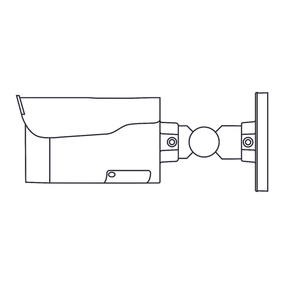
1. PRODUCT OVERVIEW PHYSICAL CHARACTERISTICS 10.27 (261) 6.1 (155) 9.96 (253) FIGURE 1-1: PHYSICAL DIMENSIONS [IN. (MM)]... - Page 6 FIGURE 1-2: PARTS PICTORIAL INDEX Mounting Bracket RJ-45 Ethernet/PoE Port Mount the camera onto surface. The Connect an Ethernet cable terminated mounting bracket is designed with 3 with RJ-45 connector to the PoE RJ-45 axes for flexible adjustment. port for both power supply and network connectivity.
- Page 7 FIGURE 1-3: INTERNAL INTERFACE PICTORIAL INDEX Micro SD Card Slot Status LEDs Micro-SD card (1 TB, included) slot Solid Red: Indicates boot up is for recording and file storage. running. After 2-3 seconds: • Solid Red to Flashing Green if boot Reset Button up is normal.
-
Page 8: Installation And Mounting
2. INSTALLATION AND MOUNTING PACKAGE CONTENTS Ensure all items listed below are included in the packing box. • Bullet Camera (Qty 1) • Plastic Anchor (Qty 6) • Self-Tapping Screw (T10) (Qty 6) • T10 Security Torx Bit (Qty 1) •... -
Page 9: Mounting Preparation
MOUNTING PREPARATION 1. Place the supplied mounting template on a mounting surface. Drill 6 mm (0.25”) outer holes (x6) at the mounting surface corresponding to the 6 indicated positions for plastic anchors. 2. Insert and hammer the plastic anchors into the drilled holes. MOUNTING THE CAMERA 1. - Page 10 2. As shown in Figure 2-3, position the camera to match the 6 holes embedded with the plastic anchors on the surface. 3. Secure the 6 tapping screws tightly to fasten the camera to the mounting surface. Plastic Anchors Tapping Screws FIGURE 2-3: MOUNTING THE CAMERA...
-
Page 11: Connecting The Cables
CONNECTING THE CABLES 1. Based on your needs, connect the power cable to the power port via one of the following 3 options. • 24 VAC: Connect a power cable that supplies 24 VAC power source to the terminal block and then insert the terminal block into the power port. •... -
Page 12: Poe Port & Waterproof Connector Wiring Procedure
POE PORT & WATERPROOF CONNECTOR WIRING PROCEDURE 1. Pass the Ethernet cable through the waterproof connector and terminate the cable with RJ-45 connector. 2. Firmly encircle the PoE port with the rubber O-ring. 3. Plug the RJ-45 connector into the PoE port securely for power supply and network connection. -
Page 13: Adjusting The Camera Position
ADJUSTING THE CAMERA POSITION • Pan Adjustment (A): Loosen the locking screw using the T10 torx wrench and rotate the A joint to adjust the camera horizontally. • Tilt Adjustment (B): Loosen the locking screw using the T10 torx wrench and rotate the B joint to adjust the camera vertically. - Page 14 ADJUSTING THE PROTECTION SHIELD HOOD This camera is designed with the capability to operate in rugged environments and may possibly be subject to the influence from sunlight and rain. The protection shield hood is attached to the camera to prevent impact from those outside effects. To adjust the protection shield hood: 1.
- Page 15 24-Hour Technical Support: Vicon Industries Inc. does not warrant that the functions contained 800-34-VICON (800-348-4266) in this equipment will meet your requirements or that the operation UK: 44/(0) 1489-566300 will be entirely error free or perform precisely as described in the Toll Free: 800-645-9116 documentation.
Need help?
Do you have a question about the ANAVIO VA-BVF08A-1TB and is the answer not in the manual?
Questions and answers