Advertisement
Quick Links
INSTRUCTION MANUAL XX173-02
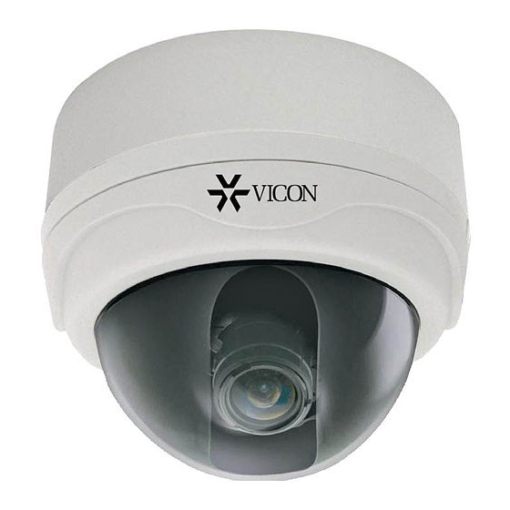
VC-600W, VC-600WS
VC-610W, VC-610WS SERIES
COLOR DOME CAMERAS
About this manual
Before installing and using the camera, please read this manual
carefully. Be sure to keep it handy for later reference.
This installation should be made by a qualified service person and
should conform to the National Electric Code, ANSI/NFPA 70 and
all local codes.
CAMERA DIMENSIONS in. (mm)
Advertisement

Summary of Contents for Vicon VC-600W
- Page 1 INSTRUCTION MANUAL XX173-02 VC-600W, VC-600WS VC-610W, VC-610WS SERIES COLOR DOME CAMERAS About this manual Before installing and using the camera, please read this manual carefully. Be sure to keep it handy for later reference. This installation should be made by a qualified service person and should conform to the National Electric Code, ANSI/NFPA 70 and all local codes.
-
Page 2: Troubleshooting
PRECAUTIONS ■ Do not open or modify Do not open the case except during maintenance and installation, as it may be dangerous and cause damage. ■ Do not put objects inside the unit Make sure that no metal objects or flammable substances get inside the camera. - Page 3 SPECIFICATION VC-600W/VC-600WS GENERAL Spec NTSC HQ Interline Transfer CCD 1/3" 410K Pixels Color 1/3" 470K Pixels Color Total Number of Pixels 811(H) x 508(V) 795(H) x 596(V) Scanning System 525 Lines 625 Lines Horizontal Resolution 550TV Lines 0.03fc, 0.3Lux(Scene) With F1.2 Lens Sensitivity to Light [30IRE] 0.45...
- Page 4 SPECIFICATION VC-600WDN/VC-600WDN-S GENERAL Spec NTSC HQ Interline Transfer CCD 1/3" 410K Pixels Color 1/3" 470K Pixels Color Total Number of Pixels 811(H) x 508(V) 795(H) x 596(V) Scanning System 525 Lines 625 Lines 550TV Lines Horizontal Resolution 0.04fc, 0.4Lux(Scene) With F1.2 Lens Sensitivity to Light [30IRE] 0.45 Gamma Correction...
-
Page 5: Lens Adjustment
LENS ADJUSTMENT AND CONNECTION ■ LENS ADJUSTMENT VC-600W/VC-600WS, VC-610W/VC-610WS, VC-600WDN/VC-600WDN-S TILT - 60˚ Zoom Focus PAN - 360˚ Set Screw (2x) 1. Adjust the panning (360˚) and tilt (60˚) position. 2. Set the zoom position by using Zoom Lever Screw. -
Page 6: Camera Settings
CAMERA SETTINGS ■ VC-600W, VC-600WS ⑥ VARIFOCAL DC LENS ⑤ ② PORTABLE CONTROL MONITOR ① ③ IR LED ④ LINE LOCK ADJUSTMENT ⑦ POWER CONNECTOR ① DIP Switch Functions (1) Compensating for backlight When backlight is too bright Normal setting CAUTION : It will be correctly set by adjusting level volume 5. - Page 7 ④ Setting Monitor Synchronization (24 VAC adaptor users) The camera offers V-phase adjustment over 360°. Vertical sync disturbance may occur when a switcher is used to switch between multiple cameras connected to one monitor. To prevent vertical sync disturbance, adjust ④*. CAUTION: When using the 12 VDC adaptor, sync setting is set to internal sync.
- Page 8 ① DIP Switch Functions (1) Confirming the iris setting ME(ON) When DC autoiris lens installed AE(OFF) When fixed iris lens is installed (2) White balance setting ATW(ON) Use this under light source below 2500K and over 9500K of Natrium (Sodium) low color temperature light AWB(OFF) Use this under light source between 2500K and 9500K of fluorescent lamp or...
- Page 9 *Before making any adjustment, confirm that the cameras are connected to the power supply with the same polarity. To make an adjustment: While observing the video outputs from the cameras on an oscilloscope, press the first camera's V-phase pushbutton. Until vertical sync from all cameras are in phase. If the first camera's adjustment phase is insufficient, adjust the second camera's V-phase contol in the oppposite direction until they are in phase.
- Page 10 ② Second Video OUT Connector (Option) If installer is setting with portable monitor, this connector is used. Be sure to terminate the last video device at 75 ohms. ③ IR LED Connector (Option) If extra IR LED board is attached, this connector is used. ④...
- Page 11 If the first camera's adjustment phase is insufficient, adjust the second INSTALLATION camera's V-phase contol in the oppposite direction until they are in phase. VC-600W/VC600WS, VC-610W/VC-610WS, VC-600WDN/VC-600WDNS VC-600WIR/VC-600WIRS...
- Page 12 Note: The VC-600W/VC-610W series can be mounted in a pendant (suspended) configuration from a wall mount, a ceiling mount or from a 1/2- inch NPT pipe with the use of the VC-600W-PLATE adapter plate and the V910-PH.
-
Page 13: Corporate Headquarters
Unit 5, 17/F, Metropole Square Lahnstrasse 2 On Yiu Street, Shatin D-24539 Neumuenster New Territories, Phone: +49 (0) 4321 8790 Hong Kong Fax: +49 (0) 4321 879 47 (852) 2145-7118 Fax: (852) 2145-7117 Internet Address: www.vicon-cctv.com Vicon Part Number 8009-8173-02-01, rev 408...


Need help?
Do you have a question about the VC-600W and is the answer not in the manual?
Questions and answers