Table of Contents
Advertisement
Quick Links
Manual
ADVANTECH
SOM-7569
COM-Express Mini Computer-on-Module with Apollo Lake
Intel® Atom™ X7-E3950, E3940, E3930 / Celeron® N33580 / N4200 Pentium® Processor,
up to -40 ... +85°C (extended Temperature)
The information contained in this document has been carefully researched and is, to the best of our
knowledge, accurate. However, we assume no liability for any product failures or damages, immediate or
consequential, resulting from the use of the information provided herein. Our products are not intended for
use in systems in which failures of product could result in personal injury. All trademarks mentioned herein
are property of their respective owners. All specifications are subject to change without notice.
Advertisement
Table of Contents

Related Manuals for Advantech SOM-7569


Summary of Contents for Advantech SOM-7569
- Page 1 Manual ADVANTECH SOM-7569 COM-Express Mini Computer-on-Module with Apollo Lake Intel® Atom™ X7-E3950, E3940, E3930 / Celeron® N33580 / N4200 Pentium® Processor, up to -40 … +85°C (extended Temperature) The information contained in this document has been carefully researched and is, to the best of our knowledge, accurate.
- Page 2 User Manual SOM-7569 COM Express Mini Module...
- Page 3 No part of this manual may be reproduced, copied, translated or transmitted in any form or by any means without the prior written permission of Advantech Co., Ltd. Information provided in this manual is intended to be accurate and reliable. How- ever, Advantech Co., Ltd.
- Page 4 Because of Advantech’s high quality-control standards and rigorous testing, most of our customers never need to use our repair service. If an Advantech product is defec- tive, it will be repaired or replaced at no charge during the warranty period. For out- of-warranty repairs, you will be billed according to the cost of replacement materials, service time and freight.
-
Page 5: Declaration Of Conformity
Class I, Division 2, Groups A, B, C and D indoor hazards. Technical Support and Assistance Visit the Advantech website at http://support.advantech.com where you can find the latest information about the product. Contact your distributor, sales representative, or Advantech's customer service center for technical support if you need additional assistance. - Page 6 Before setting up the system, check that the items listed below are included and in good condition. If any item does not accord with the table, please contact your dealer immediately. SOM-7569 CPU Module 1960079608T000 Heatspreader for N4200, N3350 CPU SKU ...
-
Page 7: Safety Instructions
The sound pressure level at the operator's position according to IEC 704-1:1982 is no more than 70 dB (A). DISCLAIMER: This set of instructions is given according to IEC 704-1. Advantech disclaims all responsibility for the accuracy of any statements contained herein. - Page 8 Don't touch any components on the CPU card or other cards while the PC is on. Disconnect power before making any configuration changes. The sudden rush of power as you connect a jumper or install a card may damage sensitive elec- tronic components. SOM-7569 User Manual...
- Page 9 SOM-7569 User Manual viii...
-
Page 10: Table Of Contents
W83627DHGSEC Super IO Configuration..........29 Figure 3.10W83627DHGSEC Super IO Configuration ....29 3.4.1 Serial Port 3 Configuration............30 Figure 3.11Serial Port 3 Configuration ........30 3.4.2 Serial Port 4 Configuration............31 Figure 3.12Serial Port 4 Configuration ........31 SOM-7569 User Manual... - Page 11 Figure 3.43Boot Setting.............. 63 Save & Exit ..................... 64 Figure 3.44Save & Exit............... 64 Chapter S/W Introduction & Installation..65 S/W Introduction ..................66 Driver Installation ..................66 4.2.1 Windows Driver Setup ..............66 4.2.2 Other OS..................66 SOM-7569 User Manual...
- Page 12 Advantech iManager ................66 Appendix A Pin Assignments .......69 SOM-7569 Type 10 Pin Assignment............70 Table A.1: SOM-7569 Row A,B ..........70 Appendix B Watchdog Timer ........73 Programming the Watchdog Timer ............74 Appendix C Programming GPIO ......75 GPIO Register..................76...
- Page 13 SOM-7569 User Manual...
-
Page 14: Chapter 1 General Information
Chapter General Information This chapter gives background information on the SOM-7569 COM Express Mini CPU Module. Sections include: Introduction Functional Block Diagram Product Specification... -
Page 15: Introduction
4.75 to 20V; this provides flexible options to fulfill various application require- ments. SOM-7569 adopts a rich array of I/O interfaces including 4 PCIe x1 for better data transmission, and offers one Intel® i210IT/i210AT LAN controller, 2 SATA Gen3, 8 USB 2.0, 2 USB3.0, 2 COM ports, SMBus, I2C, and HD audio interface functions. -
Page 16: Table 1.1: Acronyms
Serial Presence Detect – refers to serial EEPROM on DRAMs that has DRAM Module configuration information Trusted Platform Module, chip to enhance the security features of a computer system UEFI Unified Extensible Firmware Interface Watch Dog Timer SOM-7569 User Manual... -
Page 17: Functional Block Diagram
PCIE Port 0~3(GEN2) PCIE Port 5 Giga LAN Default 4 PCIex1, Optional 1 PCIex4 (BIOS modify) LPC BUS WDT / I C / FAN EIO-IS200 RS2(option with CAN Bus) GPIO SD3.0 (BOM Option) SMBus SPI BIOS SPI Bus SOM-7569 User Manual... -
Page 18: Product Specification
84 x 55 mm Feature List Table 1.2: Feature List System I/O Rev.2.1 Type 10 SOM-7569 R2.1 Type 10 PCI Express Lanes 0 - 5 1 / 4 LVDS Channel A 0 / 1 LVDS Channel B eDP on LVDS CH A Pins... -
Page 19: Table 1.3: Processor System
Fan PWM / Tachometer ** 0 / 2 Trusted Platform Modules 0 / 1 Power Rev.2.1 Type 10 SOM-7569 R2.1 Type 10 VCC_12V Contacts 12 / 12 System I/O Rev.2.1 Type 10 SOM-7569 R2.1 Type 10 PCI Express Lanes 16 - 31... -
Page 20: Table 1.4: Graphics
A-2001 standard Max. Up to 1366x768 @ Up to 3840x2160 Up to 4096×2160 Up to Resolution 60Hz @ 60 Hz @ 60 Hz 3840x2160 Option support @ 30 Hz eDP1.3 Data Rate 5.4Gb/s 5.4Gb/s 2.9Gb/s HDCP HD Audio SOM-7569 User Manual... -
Page 21: Table 1.6: Multiple-Display
2 ports USB3.0 (5.0 Gbps) and 8 ports USB2.0 (480 Mbps) which are backward compatible to USB1.x. For USB3.0, supports LPM (U0, U1, U2, and U3) man- ageability to saving power. USB3.0 Schematics USB_0_1_OC# SoC USB_OC# USB_OC0# SOM-7569 User Manual... - Page 22 Wake-on-LAN(WOL): Wake to S0 from S3/S4/S5 – USB Wake: Wake to S0 from S3 – PCIe Device Wake: depends on user inquiry and may need customized BIOS LPC Wake: depends on user inquiry and may need customized BIOS SOM-7569 User Manual...
- Page 23 Please refer Advantech SOM-7569 Series Reliability Prediction Report No: TBC. The mission of Advantech Embedded Software Services is to "Enhance quality of life with Advantech platforms and Microsoft Windows embedded technology." We enable Windows Embedded software products on Advantech platforms to more effectively support the embedded computing community.
- Page 24 Power Consumption & Performance For reference performance or benchmark data that compare with other module, please refer to “Advantech COM Performance & Power Consumption Table”. Selection Guide w/ P/N: Part No.
- Page 25 In layout checklist, it will specify the layout con- strains and recommendations for trace length, impedance, and other necessary infor- mation during design. Please contact your nearest Advantech branch office or call for getting the design documents and further advance supports. SOM-7569 User Manual...
-
Page 26: Chapter 2 Mechanical Information
Chapter Mechanical Information This chapter gives mechanical information on the SOM-7569 COM Express Mini CPU Module. Sections include: Board Information Mechanical Drawing Assembly Drawing... -
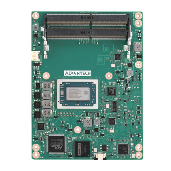
Page 27: Board Information
Board Information The figures below indicate the main chips on SOM-7569 COM Express Mini CPU Module. Please aware on these positions while designing the customer’s own carrier board to avoid mechanical problems and for thermal solutions contacts for best thermal dis- passion performance. -
Page 28: Mechanical Drawing
DDR3L Memory IC eMMC COM Express B/B Connector Figure 2.3 Board chips identify – Back Mechanical Drawing For more details about 2D/3D models, please look on Advantech’s COM support ser- vice website: http://com.advantech.com. ® Intel Pentium and Celeron N and J Series Figure 2.4 Board Mechanical Drawing - Front... -
Page 29: Figure 2.5 Board Mechanical Drawing - Front
® Intel Atom Processor E3900 Series Figure 2.5 Board Mechanical Drawing - Front Figure 2.6 Board Mechanical Drawing – Back SOM-7569 User Manual... -
Page 30: Assembly Drawing
Figure 2.7 Board Mechanical Drawing – Side Assembly Drawing These figures demonstrate the assembly order from thermal module, COM Express CPU module to carrier board. Figure 2.8 Assembly Drawing SOM-7569 User Manual... -
Page 31: Figure 2.9 Main Chip Height And Tolerance
Please consider the CPU and chip height tolerance when designing your thermal solution. ® Intel Pentium and Celeron N and J Series Figure 2.9 Main Chip Height and Tolerance ® Intel Atom Processor E3900 Series Figure 2.10 Main Chip Height and Tolerance SOM-7569 User Manual... -
Page 32: Chapter 3 Ami Bios
Chapter AMI BIOS This chapter gives BIOS setup information for the SOM-7569 COM Express Mini CPU Module. Sections include: Introduction Entering Setup Hot/Operation Key Exit BIOS Setup Utility... -
Page 33: Entering Setup
When users first enter the BIOS Setup Utility, users will enter the Main setup screen. Users can always return to the Main setup screen by selecting the Main tab. There are two Main Setup options. They are described in this section. The Main BIOS Setup screen is shown below. SOM-7569 User Manual... -
Page 34: Figure 3.2 Main Setup Screen
System Date using the <Arrow> keys. Enter new values through the keyboard. Press the <Tab> key or the <Arrow> keys to move between fields. The date must be entered in MM/DD/YY format. The time must be entered in HH:MM:SS format. SOM-7569 User Manual... -
Page 35: Advanced Bios Features Setup
Advanced BIOS Features Setup Select the Advanced tab from the SOM-7569 setup screen to enter the Advanced BIOS Setup screen. Users can select any item in the left frame of the screen, such as CPU Configuration, to go to the sub menu for that item. Users can display an Advanced BIOS Setup option by highlighting it using the <Arrow>... -
Page 36: Trusted Computing
3.3.1 Trusted Computing Figure 3.4 ACPI Settings Security Device Support Enables or Disables BIOS support for security device. OS will not show Security Device. TCG EFI protocol and INT1A interface will not be available. SOM-7569 User Manual... -
Page 37: Acpi Settings
OS. ACPI Sleep State Select the highest ACPI sleep state the system will enter when the SUSPEND button is pressed. Lock Legacy Resources Enable or Disable Lock of Legacy Resources. SOM-7569 User Manual... -
Page 38: Embedded Controller
Power Saving Mode Select Power Saving Mode Serial Port 1 Configuration Set Parameters of Serial Port 1 (COMA) Serial Port 2 Configuration Set Parameters of Serial Port 2 (COMB) Hardware Monitor Monitor hardware status SOM-7569 User Manual... -
Page 39: Serial Port 1 Configuration
3.3.4 Serial Port 1 Configuration Figure 3.7 Serial Port 1 Configuration Serial Port Enable/Disable Serial Port (COM). Change Settings Select an optimal setting for Super IO device. SOM-7569 User Manual... -
Page 40: Serial Port 2 Configuration
3.3.5 Serial Port 2 Configuration Figure 3.8 Serial Port 2 Configuration Serial Port Enable/Disable Serial Port (COM). Change Settings Select an optimal setting for Super IO device. SOM-7569 User Manual... -
Page 41: Hardware Monitor
3.3.6 Hardware Monitor Figure 3.9 Hardware Monitor Hardware Monitor Information This item shows Hardware information parameters. SOM-7569 User Manual... -
Page 42: W83627Dhgsec Super Io Configuration
Figure 3.10 W83627DHGSEC Super IO Configuration Serial Port 3 Configuration Set Parameters of Serial Port 3 Serial Port 4 Configuration Set Parameters of Serial Port 4 Parallel Port Configuration Set Parameters of Parallel Port (LPT/LPTE) SOM-7569 User Manual... -
Page 43: Serial Port 3 Configuration
3.4.1 Serial Port 3 Configuration Figure 3.11 Serial Port 3 Configuration Serial Port Enable or Disable Serial Port (COM). Change Settings Select an optimal setting for Super IO device. SOM-7569 User Manual... -
Page 44: Serial Port 4 Configuration
3.4.2 Serial Port 4 Configuration Figure 3.12 Serial Port 4 Configuration Serial Port Enable or Disable Serial Port (COM) Change Settings Select an optimal setting for Super IO device. SOM-7569 User Manual... -
Page 45: Parallel Port Configuration
Parallel Port Configuration Figure 3.13 Parallel Port Configuration Parallel Port Enable or Disable Parallel Port (LPT/LPTE). Change Settings Select an optimal setting for Super IO device. Device Mode Change the Printer Port mode. SOM-7569 User Manual... -
Page 46: Serial Port Console Redirection
COM1 Console Redirection Console Redirection Enable or Disable. COM2 Console Redirection Console Redirection Enable or Disable. Legacy Console Redirection Settings Change Legacy Console Redirection Settings. Console Redirection Console Redirection Enable or Disable. SOM-7569 User Manual... -
Page 47: Figure 3.15Legacy Console Redirection Settings
3.4.4.1 Legacy Console Redirection Settings Figure 3.15 Legacy Console Redirection Settings Legacy Console Redirection Settings Select a COM port to display redirection of Legacy OS and Legacy OPROM Messages. SOM-7569 User Manual... -
Page 48: Cpu Configuration
Number of cores to enable in each processor package. Intel Virtualization Technology When enabled, a VMM can utilize the additional hardware capabilities provided by Vanderpool Technology. VT-d Enable/Disable CPU VT-d. Monitor Mwait Enable/Disable Monitor Mwait. SOM-7569 User Manual... -
Page 49: Socket 0 Cpu Configuration
3.4.6 Socket 0 CPU Configuration Figure 3.17 Socket 0 CPU Configurations Socket 0 CPU Information Socket specific CPU Information. SOM-7569 User Manual... -
Page 50: Cpu Power Management
Power Limit 1 in Watts. Auto will program Power Limit 1 based on silicon default support value. Power Limit 1 Time Window Power Limit 1 Time Window Value in Seconds. Auto will program Power Limit 1 Time Window based on silicon default support value. SOM-7569 User Manual... -
Page 51: Network Stack Configuration
3.4.8 Network Stack Configuration Figure 3.19 Network Stack Configuration Network Stack Enable/Disable UEFI Network Stack. SOM-7569 User Manual... -
Page 52: Csm Configuration
Controls the execution of UEFI and Legacy Storage OpROM. Video Controls the execution of UEFI and Legacy Video OpROM. Other PCI devices Determines OpROM execution policy for devices other than Network, Storage, or Video. SOM-7569 User Manual... -
Page 53: Nvme Configuration
3.4.10 NVMe Configuration Figure 3.21 NVMe Configuration NVMe Configuration NVMe controller and driver information. SOM-7569 User Manual... -
Page 54: Sdio Configuration
SDIO Access Mode Auto option: Access SD device in DMA mode if controller supports it, otherwise in PIO mode. DMA option: Access SD device in DMA mode. PIO Option: Access SD device in PIO mode. SOM-7569 User Manual... -
Page 55: Usb Configuration
Maximum time the device will take before it properly reports itself to the Host Controller. ‘Auto’ uses default value: for a Root port it is 100ms, for a Hub port the delay is taken from Hub descriptor. SOM-7569 User Manual... -
Page 56: Platform Trust Technology
3.4.13 Platform Trust Technology Figure 3.24 Platform Trust Technology fTPM Enable/Disable fTPM SOM-7569 User Manual... -
Page 57: Security Configuration
3.4.14 Security Configuration Figure 3.25 Security Configuration TXE HMRFPO Enable/Disable TXE HMRFPO. TXE EOP Message Send EOP Message Before Enter OS. SOM-7569 User Manual... -
Page 58: Chipset
Chipset Select the Chipset tab from the SOM-7569 setup screen to enter the Chipset BIOS Setup screen. You can display a Chipset BIOS Setup option by highlighting it using by the <Arrow> keys. All Plug and Play BIOS Setup options are described in this sec- tion. -
Page 59: North Bridge
3.5.1 North Bridge Figure 3.27 North Bridge Above 4GB MMIO BIOS assignment Enable/Disable above 4GB MemoryMappedIO BIOS assignment. This is dis- abled automatically when Aperture Size is set to 2048MB. SOM-7569 User Manual... -
Page 60: South Bridge
3.5.2 South Bridge Figure 3.28 South Bridge Serial IRQ Mode Configure Serial IRQ Mode. SOM-7569 User Manual... -
Page 61: Uncore Configuration
Color depth and packing format Select Color depth and packing format setting. Dual LVDS mode Select Dual LVDS mode settings. LCD Panel Type Select LCD panel used by Internal Graphics Device by selecting the appropriate setup item. SOM-7569 User Manual... -
Page 62: South Cluster Configuration
PCI Express Configuration PCI Express Configuration Settings. SATA Drives Press <Enter> to select the SATA Device Configuration Setup options. SCC Configuration SCC Configuration Settings. USB Configuration USB Configuration Settings. Miscellaneous Configuration Enable/Disable Misc. Features. SOM-7569 User Manual... -
Page 63: Figure 3.31Hd-Audio Configuration
3.5.4.1 HD-Audio Configuration Figure 3.31 HD-Audio Configuration HD-Audio Support Enable/Disable HD-Audio Support. SOM-7569 User Manual... -
Page 64: Figure 3.32Pci Express Configuration
Auto: To disable unused root port automatically for the most optimum power savings. Enable: Enable PCIe root port. Disable: Disable PCIe root port. PCI Express Root Port 2 Control the PCI Express Root Port. Auto: To disable unused root port automatically for the most optimum power savings. SOM-7569 User Manual... - Page 65 Disable: Disable PCIe root port. PCI Express Root Port 3 Control the PCI Express Root Port. Auto: To disable unused root port automatically for the most optimum power savings. Enable: Enable PCIe root port. Disable: Disable PCIe root port. SOM-7569 User Manual...
-
Page 66: Figure 3.33Lan
Auto: To disable unused root port automatically for the most optimum power savings. Enable: Enable PCIe root port. Disable: Disable PCIe root port. ASPM PCI Express Active State Power Management settings. PCIe Speed Configure PCIe Speed. SOM-7569 User Manual... -
Page 67: Figure 3.34Pci Express Root Port 0 Configuration
Auto: To disable unused root port automatically for the most optimum power savings. Enable: Enable PCIe root port. Disable: Disable PCIe root port. ASPM PCI Express Active State Power Management settings. PCIe Speed Configure PCIe Speed. SOM-7569 User Manual... -
Page 68: Figure 3.35Pci Express Root Port 1 Configuration
Auto: To disable unused root port automatically for the most optimum power savings. Enable: Enable PCIe root port. Disable: Disable PCIe root port. ASPM PCI Express Active State Power Management settings. PCIe Speed Configure PCIe Speed. SOM-7569 User Manual... -
Page 69: Figure 3.36Pci Express Root Port 2 Configuration
Auto: To disable unused root port automatically for the most optimum power savings. Enable: Enable PCIe root port. Disable: Disable PCIe root port. ASPM PCI Express Active State Power Management settings. PCIe Speed Configure PCIe Speed. SOM-7569 User Manual... -
Page 70: Figure 3.37Pci Express Root Port 3 Configuration
Auto: To disable unused root port automatically for the most optimum power savings. Enable: Enable PCIe root port. Disable: Disable PCIe root port. ASPM PCI Express Active State Power Management settings. PCIe Speed Configure PCIe Speed. SOM-7569 User Manual... -
Page 71: Figure 3.38Sata Drives
2 black internal SATA ports (up to 3Gb/s supported per port) SATA Mode Selection Determines how SATA controller(s) operate. SATA Port 0 Enable or Disable SATA Port. SATA Port 1 Enable or Disable SATA Port. SOM-7569 User Manual... -
Page 72: Figure 3.39Scc Configuration
SCC Configuration Figure 3.39 SCC Configuration SCC SD Card Support (D27:F0) Enable/Disable SCC SD Card Support SCC eMMC Support (D28:F0) Enable/Disable SCC eMMC Support eMMC Max Speed Select the eMMC max Speed allowed. SOM-7569 User Manual... -
Page 73: Figure 3.40Usb Configuration
Once disabled, XHCI controller would be function disabled, none of the USB devices are detectable and usable during boot and in OS. Do not disable it unless for debug purpose. XDCI Support Enable/Disable XDCI. USB HW MODE AFE Comparators Enable/Disable USB HW MODE AFE Comparators. SOM-7569 User Manual... -
Page 74: Figure 3.41Miscellaneous Configuration
S5 State: System keeps in power-off state until power button is pressed. Wake On Lan Enable or Disable the Wake on Lan. BIOS Lock Enable/Disable the SC BIOS Lock Enable features. Required to be enabled to ensure SMM protection of flash. SOM-7569 User Manual... -
Page 75: Security Setting
Security Setting Figure 3.42 Security Setup Select Security Setup from the SOM-7569 Setup main BIOS setup menu. All Security Setup options, such as password protection is described in this section. To access the sub menu for the following items, select the item and press <Enter>: ... -
Page 76: Boot Settings
65535(0xFFF) means indefinite waiting. Bootup NumLock State Select the keyboard Numlock state. Quiet Boot Enable or Disables Quiet Boot option. Fast Boot Enable or Disable FastBoot features. Most probes are skipped to reduce time cost during boot. SOM-7569 User Manual... -
Page 77: Save & Exit
Save the changes done so fat as User Defaults. Restore User Defaults Restore the User Defaults to all the setup options Launch EFI Shell from filesystem device Attempts to Lunch EFI Shell application (Shell.efi) from one of the available file- system devices. SOM-7569 User Manual... -
Page 78: S/W Introduction & Installation
Chapter S/W Introduction & Installation Sections include: S/W Introduction Driver Installation Advantech iManager... -
Page 79: S/W Introduction
S/W Introduction The mission of Advantech Embedded Software Services is to "Enhance quality of life with Advantech platforms and Microsoft Windows embedded technology." We enable Windows Embedded software products on Advantech platforms to more effectively support the embedded computing community. Customers are freed from the hassle of dealing with multiple vendors (Hardware suppliers, System integrators, Embedded OS distributor) for projects. - Page 80 SOM-7569 User Manual...
- Page 81 SOM-7569 User Manual...
-
Page 82: Appendix A Pin Assignments
Appendix Pin Assignments This appendix gives you the infor- mation about the hardware pin assignment of the SOM-7569 COM Express Mini CPU Module. Sections include: SOM-7569 Type 10 Pin Assign- ment... -
Page 83: Som-7569 Type 10 Pin Assignment
This section gives SOM-7569 pin assignment on COM Express connector which is compliant with COM.0 R 2.1 Type 10 pin-out definitions. For more details about how to use these pins and get a design reference guide, please contact Advantech for design guide, checklist, reference schematic, and other hardware/software support. - Page 84 Table A.1: SOM-7569 Row A,B USB2- USB3- USB2+ USB3+ USB_2_3_OC# USB_0_1_OC# USB0- USB1- USB0+ USB1+ VCC_RTC EXCD1_PERST# EXCD0_PERST# EXCD1_CPPE# EXCD0_CPPE# SYS_RESET# LPC_SERIRQ CB_RESET# GPI0 GPO1 GPO2 PCIE_TX3+ PCIE_RX3+ PCIE_TX3- PCIE_RX3- PCIE_TX2+ PCIE_RX2+ PCIE_TX2- PCIE_RX2- GPI1 GPO3 PCIE_TX1+ PCIE_RX1+ PCIE_TX1- PCIE_RX1-...
- Page 85 Table A.1: SOM-7569 Row A,B PCIE_CLK_REF+ BIOS_DIS1# PCIE_CLK_REF- DDI0_HPD SPI_POWER SPI_MISO GPO0 SPI_CLK SPI_MOSI DDI0_DDC_AUX_SEL TPM_PP RSVD TYPE10# SPI_CS# SER0_TX DDI0_CTRLCLK_AUX+ SER0_RX DDI0_CTRLCLK_AUX- A100 B100 A101 SER1_TX B101 FAN_PWMOUT A102 SER1_RX B102 FAN_TACHIN A103 LID# B103 SLEEP# A104 VCC_12V B104...
-
Page 86: Appendix B Watchdog Timer
Appendix Watchdog Timer This appendix gives you the infor- mation about the watchdog timer programming on the SOM-7569 COM Express Mini CPU Module. Sections include: Watchdog Timer Programming... -
Page 87: Programming The Watchdog Timer
** WDT new driver support automatically select available IRQ number from BIOS, and then set to EC. Only Win10 support it. In other OS, it will still use IRQ number from BIOS setting as usual. For details, please refer to iManager & Software API User Manual. SOM-7569 User Manual... -
Page 88: Appendix C Programming Gpio
Appendix Programming GPIO This Appendix gives the illustra- tion of the General Purpose Input and Output pin setting. Sections include: System I/O ports... -
Page 89: Gpio Register
GPIO Register GPIO Byte Mapping H/W Pin Name BIT0 GPO0 BIT1 GPO1 BIT2 GPO2 BIT3 GPO3 BIT4 GPI0 BIT5 GPI1 BIT6 GPI2 BIT7 GPI3 For details, please refer to iManager & Software API User Manual. SOM-7569 User Manual... -
Page 90: Appendix D System Assignments
Appendix System Assignments This appendix gives you the infor- mation about the system resource allocation on the SOM-7569 COM Express Mini CPU Module. Sections include: System I/O ports Interrupt Assignments 1st MB Memory Map... -
Page 91: System I/O Ports
00B8-00B9 Programmable interrupt controller 00BC-00BD Programmable interrupt controller 0280-028F Motherboard resources 0290-029F Motherboard resources 0299-029A Motherboard resources 029E-02AD Motherboard resources 02A0-02BF Motherboard resources 02C0-02DF Motherboard resources 02E8-02EF Communications Port (COM4) 02F0-02E7 Motherboard resources 02F8-02FF Communications Port (COM2) SOM-7569 User Manual... - Page 92 Motherboard resources E000-EFFF Intel(R) Celeron(R)/Pentium(R)Processor PCI Express Root Port – 5AD7 F000-F03F Intel(R) HD Graphics F040-F05F Intel(R) Celeron(R)/Pentium(R) Processor SMBus - 5AD4 F060-F07F Standard SATA AHCI Controller F080-F083 Standard SATA AHCI Controller F090-F097 Standard SATA AHCI Controller SOM-7569 User Manual...
-
Page 93: Interrupt Assignments
Intel(R) Celeron(R)/Pentium(R)Processor PCI Express Root Port – 5ADB IRQ FFFFFFFC (-4) Intel(R) Celeron(R)/Pentium(R)Processor PCI Express Root Port – 5ADA IRQ FFFFFFFD (-3) Intel(R) Celeron(R)/Pentium(R)Processor PCI Express Root Port – 5AD9 IRQ FFFFFFFE (-2) Intel(R) Celeron(R)/Pentium(R)Processor PCI Express Root Port – 5AD8 SOM-7569 User Manual... -
Page 94: 1St Mb Memory Map
0xE0000000-0xEFFFFFFF Motherboard resources 0xE0000000-0xEFFFFFFF PCI Express Root Complex 0xFEA00000-0xFEAFFFFF Motherboard resources 0xFED00000-0xFED003FF High precision even timer 0xFED01000-0xFED01FFF Motherboard resources 0xFED03000-0xFED03FFF Motherboard resources 0xFED06000-0xFED06FFF Motherboard resources 0xFED08000-0xFED09FFF Motherboard resources 0xFED1C000-0xFED1CFFF Motherboard resources 0xFED80000-0xFEDBFFFF Motherboard resources 0xFEE00000-0xFEEFFFFF Motherboard resources SOM-7569 User Manual... - Page 95 No part of this publication may be reproduced in any form or by any means, electronic, photocopying, recording or otherwise, without prior written permis- sion of the publisher. All brand and product names are trademarks or registered trademarks of their respective companies. © Advantech Co., Ltd. 2017...
- Page 96 Our company network supports you worldwide with offices in Germany, Austria, Switzerland, Great Britain and the USA. For more information please contact: Headquarters Germany FORTEC Elektronik AG Lechwiesenstr. 9 86899 Landsberg am Lech Phone: +49 8191 91172-0 E-Mail: sales@fortecag.de Internet: www.fortecag.de Fortec Group Members FORTEC Elektronik AG...
Need help?
Do you have a question about the SOM-7569 and is the answer not in the manual?
Questions and answers