Table of Contents
Advertisement
Quick Links
Advertisement
Table of Contents

Related Manuals for Advantech SOM-5894


Summary of Contents for Advantech SOM-5894
- Page 1 User Manual SOM-5894...
- Page 2 No part of this manual may be reproduced, copied, translated or transmitted in any form or by any means without the prior written permission of Advantech Co., Ltd. Information provided in this manual is intended to be accurate and reliable. How- ever, Advantech Co., Ltd.
-
Page 3: Declaration Of Conformity
Class I, Division 2, Groups A, B, C and D indoor hazards. Technical Support and Assistance Visit the Advantech website at http://support.advantech.com where you can find the latest information about the product. Contact your distributor, sales representative, or Advantech's customer service center for technical support if you need additional assistance. -
Page 4: Packing List
Before setting up the system, check that the items listed below are included and in good condition. If any item does not accord with the table, please contact your dealer immediately. SOM-5894 CPU module 1 x Heatspreader (1960058957N001) SOM-5894 User Manual... -
Page 5: Safety Instructions
The sound pressure level at the operator's position according to IEC 704-1:1982 is no more than 70 dB (A). DISCLAIMER: This set of instructions is given according to IEC 704-1. Advantech disclaims all responsibility for the accuracy of any statements contained herein. - Page 6 Don't touch any components on the CPU card or other cards while the PC is on. Disconnect power before making any configuration changes. The sudden rush of power as you connect a jumper or install a card may damage sensitive elec- tronic components. SOM-5894 User Manual...
-
Page 7: Table Of Contents
Exit BIOS Setup Utility ................15 Chapter S/W Introduction & Installation ..17 S/W Introduction..................18 Driver Installation ..................18 4.2.1 Windows Driver Setup ..............18 4.2.2 Other OS..................18 Advantech iManager ................19 Appendix A Pin Assignment .........21 SOM-5894 User Manual... - Page 8 SOM-5894 Type 6 Pin Assignment............22 Appendix B Watchdog Timer........ 27 Programming the Watchdog Timer ............28 Appendix C Programming GPIO......29 GPIO Register..................30 Appendix D System Assignments......31 System I/O Ports..................32 Table D.1: System I/O Ports ............32 DMA Channel Assignments ..............
-
Page 9: Chapter 1 General Information
Chapter General Information This chapter gives background information on the SOM-5894 CPU Computer on Module. Sections include: Introduction Specification Functional Block Diagram... -
Page 10: Introduction
Introduction SOM-5894 is a COM-Express Basic module with pin-out Type 6 that fully complies with the PICMG (PCI Industrial Computer Manufactures Group) COM.0 R2.1 specifi- cation. The CPU module incorporates an Intel 4th Generation Core i processor, PCH QM87, and other peripheral chips. The Intel latest processor uses 22nm and 3D Tri- gate transistor technologies that brings 13% performance improvement over previ- ous versions, and integrates a powerful Intel HD Graphic 4600 as well as DX11.1,... -
Page 11: Display
Expansion Interface PCI Express x16: Supports default 1 port PCIe x16 compliant to PCIe Gen3* (8.0 GT/s) specification, several configurable combinations may need BOM modifies. Please contact to Advantech sales or FAE for more detail. Default Option 1 Option 2 ... -
Page 12: I/O
LPC Bus SMBus I2C Bus: 100 KHz (up to 400 KHz with BIOS modification. Please contact Advantech sales or FAE for more details) SPI: Supports SPI BIOS only 1.2.5 Ethernet: Intel I217LM Gigabit LAN supports 10/100/1000 Mbps Speed SATA: Supports 4 ports SATA Gen3 (6 Gb/s) ... -
Page 13: Functional Block Diagram
6 PCIe x1 4 USB 3.0 HD Audio 4 SATA3 QM87 1 PCIex1 Ethernet Giga LAN WGI217LM 1 PCIex1 LPC BUS WDT / GPIO / I iManager RS1 / RS2 / FAN (Optional) SMBus SPI Bus SPI BIOS SOM-5894 User Manual... - Page 14 SOM-5894 User Manual...
-
Page 15: Chapter 2 Mechanical Information
Chapter Mechanical Information This chapter gives mechanical information on the SOM-5894 CPU Computer on Module. Sections include: Board Information Mechanical Drawing Assembly Drawing Main Chip Height... -
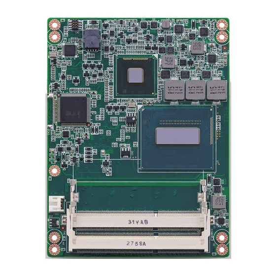
Page 16: Board Information
Board Information The figures below indicate the main chips on SOM-5894 Computer-on-Module. Please aware of these positions while designing your own carrier board to avoid mechanical problems and thermal solutions for best heat dispassion performance. OnModule Smart Fan Connector DDR3L... -
Page 17: Mechanical Drawing
Mechanical Drawing For more detail about 2D/3D models, please find on Advantech COM support service website http://com.advantech.com. 80.90 48.96 27.10 14.10 (11.4) Figure 2.3 Board Mechanical Drawing - Front ø2.7 ø6.0 Figure 2.4 Board Mechanical Drawing - Back SOM-5894 User Manual... -
Page 18: Assembly Drawing
These figures demonstrate the assembly order from the thermal module, and the COM module to the carrier board. Figure 2.5 Assembly Drawing There are 4 reserved screw holes for SOM-5894 to be pre-assembled with the heat spreader. Figure 2.6 Heatspreader Pre-Assembly... -
Page 19: Main Chips Height
Main Chip Height Please consider the CPU and chip height tolerance when designing your thermal solution. Figure 2.7 Main Chip Height and Tolerance SOM-5894 User Manual... - Page 20 SOM-5894 User Manual...
-
Page 21: Chapter 3 Ami Bios
Chapter AMI BIOS Sections include: Introduction Entering Setup Hot / Operation Key Exit BIOS Setup Utility... -
Page 22: Introduction
Figure 3.1 BIOS Setup Utility Main Screen AMI's BIOS ROM has a built-in Setup program that allows users to modify the basic system configuration. This information is stored in battery-backed CMOS so it retains the Setup information when the power is turned off. SOM-5894 User Manual... -
Page 23: Entering Setup
Switch to the Exit tab of the BIOS Setup Utility and select "Save changes and Exit". The system will then restart. There are several exit methods users can select. Or you use the F4 key to exit the BIOS Setup Utility. SOM-5894 User Manual... - Page 24 SOM-5894 User Manual...
-
Page 25: Chapter 4 S/W Introduction & Installation
Chapter S/W Introduction & Installation Sections include: S/W Introduction Driver Installation Advantech iManager... -
Page 26: S/W Introduction
S/W Introduction The mission of Advantech Embedded Software Services is to "Enhance quality of life with Advantech platforms and Microsoft Windows embedded technology." We enable Windows Embedded software products on Advantech platforms to more effectively support the embedded computing community. Customers are freed from the hassle of dealing with multiple vendors (Hardware suppliers, System integrators, Embedded OS distributor) for projects. -
Page 27: Advantech Imanager
It makes these embedded features easier to integrate, speed up develop- ing schedule, and provide the customer's software continuity while upgrade hard- ware. For more details of how to use the APIs and utilities, please refer to Advantech iManager 2.0 Software API User Manual. - Page 28 SOM-5894 User Manual...
-
Page 29: Appendix A Pin Assignment
Appendix Pin Assignment This appendix gives you the infor- mation about the hardware pin assignment of the SOM-5894 CPU System on Module. Sections include: SOM-5894 Type 6 Pin Assign- ment... -
Page 30: Som-5894 Type 6 Pin Assignment
SOM-5894 Type 6 Pin Assignment This section gives SOM-5894 pin assignment on COM Express connector which compliant with COMR.0 R2.1 Type 6 pin-out definitions. More details about how to use these pins and get design reference, please contact to Advantech for design guide, checklist, reference schematic, and other hardware/software supports. - Page 31 PCIE_RX0+ PCIE_TX0- PCIE_RX0- LVDS_A0+ LVDS_B0+ LVDS_A0- LVDS_B0- LVDS_A1+ LVDS_B1+ LVDS_A1- LVDS_B1- LVDS_A2+ LVDS_B2+ LVDS_A2- LVDS_B2- LVDS_VDD_EN LVDS_B3+ LVDS_A3+ LVDS_B3- LVDS_A3- LVDS_BKLT_EN LVDS_A_CK+ LVDS_B_CK+ LVDS_A_CK- LVDS_B_CK- LVDS_I2C_CK LVDS_BKLT_CTRL LVDS_I2C_DAT VCC_5V_SBY GPI3 VCC_5V_SBY RSVD VCC_5V_SBY eDP_HPD VCC_5V_SBY PCIE0_CK_REF+ BIOS_DIS1# SOM-5894 User Manual...
- Page 32 A106 VCC_12V B106 VCC_12V A107 VCC_12V B107 VCC_12V A108 VCC_12V B108 VCC_12V A109 VCC_12V B109 VCC_12V A110 B110 SOM-5894 Row C, D USB_SSRX0- USB_SSTX0- USB_SSRX0+ USB_SSTX0+ USB_SSRX1- USB_SSTX1- USB_SSRX1+ USB_SSTX1+ USB_SSRX2- USB_SSTX2- USB_SSRX2+ USB_SSTX2+ USB_SSRX3- USB_SSTX3- USB_SSRX3+ USB_SSTX3+ DDI1_PAIR6+ DDI1_AUX+...
- Page 33 PEG_RX0+ PEG_TX0+ PEG_RX0- PEG_TX0- TYPE0# PEG_LANE_RV# PEG_RX1+ PEG_TX1+ PEG_RX1- PEG_TX1- TYPE1# TYPE2# PEG_RX2+ PEG_TX2+ PEG_RX2- PEG_TX2- PEG_RX3+ PEG_TX3+ PEG_RX3- PEG_TX3- RSVD RSVD RSVD RSVD PEG_RX4+ PEG_TX4+ PEG_RX4- PEG_TX4- RSVD PEG_RX5+ PEG_TX5+ PEG_RX5- PEG_TX5- PEG_RX6+ PEG_TX6+ PEG_RX6- PEG_TX6- SOM-5894 User Manual...
- Page 34 D100 C101 PEG_RX15+ D101 PEG_TX15+ C102 PEG_RX15- D102 PEG_TX15- C103 D103 C104 VCC_12V D104 VCC_12V C105 VCC_12V D105 VCC_12V C106 VCC_12V D106 VCC_12V C107 VCC_12V D107 VCC_12V C108 VCC_12V D108 VCC_12V C109 VCC_12V D109 VCC_12V C110 D110 SOM-5894 User Manual...
-
Page 35: Appendix B Watchdog Timer
Appendix Watchdog Timer This appendix gives you the infor- mation about the watchdog timer programming on the SOM-5894 CPU System on Module. Sections include: Watchdog Timer Programming... -
Page 36: Programming The Watchdog Timer
EC. Only Win XP, Win7 and Win8 support it. In other OS, it will still use IRQ number from BIOS setting as usual. For details, please refer to iManager & Software API User Manual: SOM-5894 User Manual... -
Page 37: Appendix C Programming Gpio
Appendix Programming GPIO This Appendix gives the illustra- tion of the General Purpose Input and Output pin setting. Sections include: System I/O Ports... -
Page 38: Gpio Register
GPIO Register GPIO Byte Mapping H/W Pin Name BIT0 GPO0 BIT1 GPO1 BIT2 GPO2 BIT3 GPO3 BIT4 GPI0 BIT5 GPI1 BIT6 GPI2 BIT7 GPI3 For details, please refer to iManager & Software API User Manual. SOM-5894 User Manual... -
Page 39: Appendix D System Assignments
Appendix System Assignments This appendix gives you the infor- mation about the system resource allocation on the SOM-5894 CPU System on Module. Sections include: System I/O ports DMA Channel Assignments Interrupt Assignments 1st MB Memory Map... -
Page 40: System I/O Ports
Motherboard resources 0454-0457 Motherboard resources 0458-047F Motherboard resources 04D0-04D1 Programmable interrupt controller 0500-057F Motherboard resources 0680-069F Motherboard resources 0778-077F ECP Printer Port (LPT1) 0A79-0A79 ISAPNP Read Data Port 164E-164F Motherboard resources F000-F03F Video Controller F040-F05F SM Bus Controller SOM-5894 User Manual... -
Page 41: Dma Channel Assignments
Standard 101/102-Key or Microsoft Natural PS/2 Keyboard IRQ 3 Communications Port (COM2) IRQ 4 Communications Port (COM1) IRQ 8 System CMOS/real time clock IRQ 9 Microsoft ACPI-Compliant System IRQ 12 PS/2 Compatible Mouse IRQ 13 Numeric data processor SOM-5894 User Manual... -
Page 42: 1St Mb Memory Map
High precision event timer FED10000-FED17FFF Motherboard resources FED18000-FED18FFF Motherboard resources FED19000-FED19FFF Motherboard resources FED1C000-FED1FFFF Motherboard resources FED20000-FED3FFFF Motherboard resources FFE40000-FED44FFF System board FED45000-FED8FFFF Motherboard resources FED90000-FED93FFF Motherboard resources FEE00000-FEEFFFFF Motherboard resources FF000000-FFFFFFFF Intel 82802 Firmware Hub Device SOM-5894 User Manual... - Page 43 SOM-5894 User Manual...
- Page 44 No part of this publication may be reproduced in any form or by any means, electronic, photocopying, recording or otherwise, without prior written permis- sion of the publisher. All brand and product names are trademarks or registered trademarks of their respective companies. © Advantech Co., Ltd. 2013...
Need help?
Do you have a question about the SOM-5894 and is the answer not in the manual?
Questions and answers