Table of Contents
Advertisement
Quick Links
Advertisement
Table of Contents

Related Manuals for Advantech SOM-5897


Summary of Contents for Advantech SOM-5897
- Page 1 User Manual SOM-5897 COM Express Compact Module...
- Page 2 No part of this manual may be reproduced, copied, translated or transmitted in any form or by any means without the prior written permission of Advantech Co., Ltd. Information provided in this manual is intended to be accurate and reliable. How- ever, Advantech Co., Ltd.
- Page 3 Class I, Division 2, Groups A, B, C and D indoor hazards. Technical Support and Assistance Visit the Advantech website at http://support.advantech.com where you can find the latest information about the product. Contact your distributor, sales representative, or Advantech's customer service center for technical support if you need additional assistance.
- Page 4 Before setting up the system, check that the items listed below are included and in good condition. If any item does not accord with the table, please contact your dealer immediately. SOM-5897 CPU module 1 x Heatspreader (1960073944N001) SOM-5897 User Manual...
- Page 5 The sound pressure level at the operator's position according to IEC 704-1:1982 is no more than 70 dB (A). DISCLAIMER: This set of instructions is given according to IEC 704-1. Advantech disclaims all responsibility for the accuracy of any statements contained herein.
- Page 6 Don't touch any components on the CPU card or other cards while the PC is on. Disconnect power before making any configuration changes. The sudden rush of power as you connect a jumper or install a card may damage sensitive elec- tronic components. SOM-5897 User Manual...
-
Page 7: Table Of Contents
Driver Installation ..................54 4.2.1 Windows Driver Setup ..............54 4.2.2 Other OS..................54 Advantech iManager ................55 Appendix A Pin Assignment .........57 SOM-5897 Type 6 Pin Assignment............58 Appendix B Watchdog Timer ........63 Programming the Watchdog Timer ............64 SOM-5897 User Manual... - Page 8 Table D.1: System I/O ports............68 DMA Channel Assignments ..............69 Table D.2: DMA Channel Assignments ........69 Interrupt Assignments ................69 Table D.3: Interrupt Assignments ..........69 1st MB Memory Map................70 Table D.4: 1st MB Memory Map ..........70 SOM-5897 User Manual viii...
-
Page 9: Chapter 1 General Information
Chapter General Information This chapter gives background information on the SOM-5897 CPU Computer on Module. Sections include: Introduction Specification Functional Block Diagram... -
Page 10: Introduction
8 x PCIex1 as well as x4, x8 configurations if requested. Most important of all, SOM-5897 adopts a 28mm low profile cooler with a TDP of 45watt at 60°C ambient temperature (optional accessory). SOM-5897 is suitable for rich I/O applications with high performance requirements, such as ultra sound, military, broadcasting, and industrial automation fields. -
Page 11: Display
PCI Express x1: Supports default 8 PCIe x1 compliant ports to PCIe Gen3 (8.0 GT/s) specification; optionally configurable to PCIe x4 or PCIe x2. Several con- figurable combinations may need BIOS modification. Please contact Advantech sales or FAE for more details. -
Page 12: I/O
Operating: 0 ~ 60 ° C (32 ~ 140 ° F) – Storage: -40 ~ 85 ° C (-40 ~ 185 ° F) – Humidity Specification: – Operating: 40 ° C @ 95% relative humidity, non-condensing Storage: 60 ° C @ 95% relative humidity, non-condensing – SOM-5897 User Manual... -
Page 13: Functional Block Diagram
2 PCIe x1 PCIe x1 Intel I219LM HD Audio 8 USB 2.0 4 USB 3.0 4 SATA 3.0 Intel SMBus QM170 / CM236 EFI BIOS TPM2.0 (Optional) WDT / GPIO / I iManager RS1 / RS2 / FAN SOM-5897 User Manual... - Page 14 SOM-5897 User Manual...
-
Page 15: Chapter 2 Mechanical Information
Chapter Mechanical Information This chapter gives mechanical information on the SOM-5897 CPU Computer on Module. Sections include: Board Information Mechanical Drawing Assembly Drawing... -
Page 16: Board Information
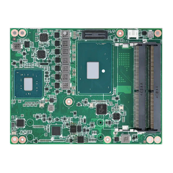
Board Information The figures below indicate the main chips on SOM-5897 Computer-on-Module. Please be aware of these positions while designing your own carrier board to avoid mechanical issues, as well as designing thermal solution contact points for best ther- mal dissipation performance. -
Page 17: Mechanical Drawing
Mechanical Drawing For more details about 2D/3D models, please look on the Advantech COM support service website http://com.advantech.com. 114.8 100.3 90.21 67.71 48.21 14.96 10.2 Figure 2.3 Board Mechanical Drawing - Front Figure 2.4 Board Mechanical Drawing - Back SOM-5897 User Manual... -
Page 18: Assembly Drawing
Assembly order for the thermal module and COM module onto the carrier board. Semi-Cooler Heat Spreader SOM-5897 Stand off Nut Carrier Board Figure 2.5 Assembly Drawing (Reference Only) There are 3 reserved screw holes for SOM-5897 to be pre-assembled with the heat spreader. SOM-5897 User Manual... -
Page 19: Chapter 3 Bios Operation
Chapter BIOS Operation This chapter gives BIOS setup information for the SOM-5897 CPU Computer on Module. Sections include: Introduction Entering Setup Hot / Operation Key Exit BIOS Setup Utility... -
Page 20: Entering Setup
Entering Setup SOM-5897 BIOS has been stored into a flash ROM which is inserted into a BIOS socket on the board. With the BIOS Setup program, users can modify BIOS settings and control various system features. This chapter describes the basic navigation of the SOM-5897 BIOS setup screens. -
Page 21: Main Setup
Use this option to change the system time and date. Highlight System Time or System Date using the <Arrow> keys. Enter new values through the keyboard. Press the <Tab> key or the <Arrow> keys to move between fields. - System Date: mm/dd/yyyy - System Time: hh/mm/ss SOM-5897 User Manual... -
Page 22: Advanced Bios Features Setup
3.1.2 Advanced BIOS Features Setup Select the Advanced tab from the SOM-5897 setup screen to enter the Advanced BIOS Setup screen. Users can select any item in the left frame of the screen, such as CPU Configuration, to go to the sub menu for that item. Users can display an Advanced BIOS Setup option by highlighting it using the <Arrow>... - Page 23 3.1.2.1 Trusted Computing Security Device Support Enables or Disables BIOS support for security devices. The OS will not show the security device. TCG EFI protocol and INT1A interface will not be available. SOM-5897 User Manual...
- Page 24 This item allows users to select the highest ACPI sleep state the system will enter when the suspend button is pressed. S3 Video Repost This item allows users to enable or disable S3 Video Repost. SOM-5897 User Manual...
- Page 25 Activate Remote Assistance Process Trigger CIRA boot USB Provisioning of AMT Enable/disable of AMT USB provisioning PET Progress This item is able for user to enable/disable PET events progress to receive PET events or not. SOM-5897 User Manual...
- Page 26 Selects TPM device: PTT or dTPM. PTT- Enable PTT in SkuMgr dTPM 1.2 – Disable PTT in SkuMgr warning. PTT/ dTPM will be disable and all data saved on it will be lost. Firmware Update Configuration Configure Management Engine Technology Parameters. SOM-5897 User Manual...
- Page 27 ME FW image re-flash This is for enable or disable ME FW image re-flash function. 3.1.2.5 W83627DHG Super IO Configuration Serial Port 1 Configuration Set parameters of serial Port 1 (COMA) SOM-5897 User Manual...
- Page 28 Set parameters of serial Port 2 (COMB) Parallel Port Configuration Set parameters of parallel Port (LPT/ LPTE) Serial Port 1 Configuration – Serial Port Enable or Disable Serial Port (COM) – Change Settings Select an optimal setting for Super IO device. SOM-5897 User Manual...
- Page 29 Serial Port 2 Configuration – Serial Port Enable or Disable Serial Port (COM) – Change Settings Select an optimal setting for Super IO device. Parallel Port Configuration SOM-5897 User Manual...
- Page 30 Power Saving Mode Select ite8518 power saving mode Serial Port 3 Configuration Set parameters of serial port 3 (COMA) Serial Port 4 Configuration Set parameters of serial port 4 (COMB) Hardware Monitor Monitor hardware status SOM-5897 User Manual...
- Page 31 Serial Port 3 Configuration – Serial Port Enable or Disable Serial Port (COM) – Change Settings Select an optimal setting for Super IO device. Serial Port 4 Configuration SOM-5897 User Manual...
- Page 32 – Serial Port Enable or Disable Serial Port (COM) – Change Settings Select an optimal setting for Super IO device. Hardware Monitor Hardware Monitor Monitor hardware status SOM-5897 User Manual...
- Page 33 Serial Port Console Redirection COM1 Console Redirection Console Redirection enable or disable COM2 Console Redirection Console Redirection enable or disable COM3 Console Redirection Console Redirection enable or disable COM4 Console Redirection Console Redirection enable or disable SOM-5897 User Manual...
- Page 34 Legacy Console Redirection Settings Legacy Console Redirection Select a COM port to display redirection of legacy OS and legacy OPROM mes- sage 3.1.2.8 CPU Configuration SOM-5897 User Manual...
- Page 35 This item allows users to set how many processor cores should be active. Intel Virtualization Technology When enable, a VMM can utilize the additional hardware capabilities provided by vanderpool technology. Intel(R) SpeedStep(tm) Allows more than two frequency ranges to be supported. Turbo Mode Turbo Mode. SOM-5897 User Manual...
- Page 36 Determines how SATA controller (s) operate. Port 0 Enable or disable SATA port Port 1 Enable or disable SATA port Port 2 Enable or disable SATA port Port 3 Enable or disable SATA port SOM-5897 User Manual...
- Page 37 3.1.2.10 Network Stack Configuration Network Stack Enable/Disable UEFI Network Stack 3.1.2.11 CSM Configuration CSM Support Enable/Disable CSM Support SOM-5897 User Manual...
- Page 38 Disable option will keep USB devices available only for EFI applications. XHCI Hand-off This is a workaround for OS without XHCI ownership change should be claimed by XHCI driver. USB Mass Storage Driver Support Enable/Disable USB Mass Storage Driver Support. SOM-5897 User Manual...
-
Page 39: Chipset
3.1.3 Chipset Select the Chipset tab from the SOM-5897 setup screen to enter the Chipset BIOS Setup screen. You can display a Chipset BIOS Setup option by highlighting it using the <Arrow> keys. All Plug and Play BIOS Setup options are described in this sec- tion. - Page 40 System Agent Bridge Name VT-d VT-d capability Above 4GB MMIO BIOS assignment Enable/disable above 4GB memory mapped IO BIOS assignment. This is dis- abled automatically when aperture size is set to 2048MB. SOM-5897 User Manual...
- Page 41 Graphics Configuration – Primary Display Select IGFX/PEG/PCI Graphics device should be primary display or select SG for switchable Gfx. – Internal Graphics Keep IGFX enabled based on the setup options. – LCD Control LCD Control SOM-5897 User Manual...
- Page 42 LCD Control LCD Panel Type Select LCD panel used by internal graphics device by selecting the appropri- ate setup item. Panel Scaling Select LCD panel used by internal graphics device. SOM-5897 User Manual...
- Page 43 PEG Port Configuration – PEG 0:1:0 Link and Speed Information – Enable Root Port Enable or disable the root port – Max Link Speed SOM-5897 User Manual...
- Page 44 Detect Non-Compliance PCI Express device in PEG. – Program PCIe ASPM after OpROM Enabled: PCIe ASPM will be programmed after OpROM. Disable: PCIe ASPM will be programmed before OpROM. – PCIe Spread Spectrum Clocking Allows disable spread spectrum clocking for compliance testing. SOM-5897 User Manual...
- Page 45 Memory Configuration This page shows memory information. 3.1.3.2 PCH-IO Configuration PCI Express Configuration PCI Express Configuration settings. SOM-5897 User Manual...
- Page 46 Configure serial IRQ mode. State After G3 Specify what state to go to when power is re-applied after a power failure (G3 state). PCI Express Configuration – PCI Express Root Port 0-7 PCI Express Root Port 0-7 settings. SOM-5897 User Manual...
- Page 47 Controls the PCI Express Root Port ASPM Support Sets the ASPM level: Force L0s – Force all links to L0s State Auto – BIOS auto configure Disable – disable ASPM PCIe Speed Select PCI Express port speed. SOM-5897 User Manual...
- Page 48 Controls the PCI Express Root Port ASPM Support Set the ASPM level: Force L0s – Force all links to L0s State Auto – BIOS auto configure Disable – disable ASPM PCIe Speed Selects PCI Express port speed. SOM-5897 User Manual...
- Page 49 Controls the PCI Express Root Port ASPM Support Set the ASPM level: Force L0s – Force all links to L0s State Auto – BIOS auto configure Disable – disable ASPM PCIe Speed Selects PCI Express port speed. SOM-5897 User Manual...
- Page 50 Controls the PCI Express Root Port ASPM Support Sets the ASPM level: Force L0s – Force all links to L0s State Auto – BIOS auto configure Disable – disable ASPM PCIe Speed Selects PCI Express port speed. SOM-5897 User Manual...
- Page 51 Controls the PCI Express Root Port ASPM Support Sets the ASPM level: Force L0s – Force all links to L0s State Auto – BIOS auto configure Disable – disable ASPM PCIe Speed Selects PCI Express port speed. SOM-5897 User Manual...
- Page 52 Controls the PCI Express Root Port ASPM Support Set the ASPM level: Force L0s – Force all links to L0s State Auto – BIOS auto configure Disable – disable ASPM PCIe Speed Selects PCI Express port speed. SOM-5897 User Manual...
- Page 53 Sets the ASPM level: Force L0s – Force all links to L0s State Auto – BIOS auto configure Disable – disable ASPM PCIe Speed Selects PCI Express port speed. Hot Plug Enables or disables PCI Express Hot Plug SOM-5897 User Manual...
- Page 54 Sets the ASPM level: Force L0s – Force all links to L0s State Auto – BIOS auto configure Disable – disable ASPM PCIe Speed Selects PCI Express port speed. Hot Plug Enables or disables PCI Express Hot Plug SOM-5897 User Manual...
- Page 55 USB Configuration – XHCI Disable Compliance Mode Options to disable compliance mode. Default is FALSE to not disable compli- ance mode. Set TRUE to disable compliance mode. SOM-5897 User Manual...
- Page 56 HD Audio Configuration – HD Audio Controls detection of the HD-Audio device. Disable = HDA will be unconditionally disabled Enable = HDA will be unconditionally enabled Auto = HDA will be enabled if present, disabled otherwise. SOM-5897 User Manual...
-
Page 57: Security
3.1.4 Security Select Security Setup from the SOM-5897 main BIOS setup menu. All Security Setup options, such as password protection are described in this section. To access the sub menu for the following items, select the item and press <Enter>: Change Administrator / User Password: Select this option and press <ENTER>... -
Page 58: Boot Settings
This item allows users to enable or disable boot with initialization of a minimal set of devices required to launch active boot option. Has no effect for BBS boot options. New Boot Option Policy Controls the placement of newly detected UEFI boot options SOM-5897 User Manual... -
Page 59: Save & Exit
3.1.6.5 Save Changes When users have completed system configuration, select this option to save changes without exit BIOS setup menu. 3.1.6.6 Discard Changes Select this option to discard any current changes and load previous system configu- ration. SOM-5897 User Manual... - Page 60 3.1.6.7 Restore Defaults The SOM-5897 automatically configures all setup items to optimal settings when users select this option. Optimal Defaults are designed for maximum system perfor- mance, but may not work best for all computer applications. In particular, do not use the Optimal Defaults if the user's computer is experiencing system configuration problems.
-
Page 61: Chapter 4 S/W Introduction & Installation
Chapter S/W Introduction & Installation Sections include: S/W Introduction Driver Installation Advantech iManager... -
Page 62: S/W Introduction
S/W Introduction The mission of Advantech Embedded Software Services is to "Enhance quality of life with Advantech platforms and Microsoft Windows embedded technology." We enable Windows Embedded software products on Advantech platforms to more effectively support the embedded computing community. Customers are freed from the hassle of dealing with multiple vendors (Hardware suppliers, System integrators, Embedded OS distributor) for projects. -
Page 63: Advantech Imanager
More details of how to use the APIs and utilities, please refer to the Advantech iManager 2.0 Software API User Manual. SOM-5897 User Manual... - Page 64 SOM-5897 User Manual...
-
Page 65: Appendix A Pin Assignment
Appendix Pin Assignment This appendix gives you the infor- mation about the hardware pin assignment of the SOM-5897 CPU System on Module. Sections include: SOM-5897 Type 6 Pin Assign- ment... -
Page 66: Som-5897 Type 6 Pin Assignment
This section gives SOM-5897 pin assignment on COM Express connector which compliant with COMR.0 R2.1 Type 6 pin-out definitions. More details about how to use these pins and get design reference, please contact to Advantech for design guide, checklist, reference schematic, and other hardware/software supports. - Page 67 LVDS_A1- LVDS_B1- LVDS_A2+ LVDS_B2+ LVDS_A2- LVDS_B2- LVDS_VDD_EN LVDS_B3+ LVDS_A3+ LVDS_B3- LVDS_A3- LVDS_BKLT_EN GND (FIXED) GND (FIXED) LVDS_A_CK+ LVDS_B_CK+ LVDS_A_CK- LVDS_B_CK- LVDS_I2C_CK LVDS_BKLT_CTRL LVDS_I2C_DAT VCC_5V_SBY GPI3 VCC_5V_SBY VCC_5V_SBY eDP_HPD VCC_5V_SBY PCIE_CLK_REF+ BIOS_DIS1# PCIE_CLK_REF- VGA_RED GND (FIXED) GND (FIXED) SOM-5897 User Manual...
- Page 68 A107 VCC_12V B107 VCC_12V A108 VCC_12V B108 VCC_12V A109 VCC_12V B109 VCC_12V A110 GND (FIXED) B110 GND (FIXED) SOM-5897 Row C,D GND (FIXED) GND (FIXED) USB_SSRX0- USB_SSTX0- USB_SSRX0+ USB_SSTX0+ USB_SSRX1- USB_SSTX1- USB_SSRX1+ USB_SSTX1+ USB_SSRX2- USB_SSTX2- USB_SSRX2+ USB_SSTX2+ GND (FIXED) GND (FIXED)
- Page 69 PEG_TX0- PEG_LANE_RV# PEG_RX1+ PEG_TX1+ PEG_RX1- PEG_TX1- TYPE2# PEG_RX2+ PEG_TX2+ PEG_RX2- PEG_TX2- GND (FIXED) GND (FIXED) PEG_RX3+ PEG_TX3+ PEG_RX3- PEG_TX3- PEG_RX4+ PEG_TX4+ PEG_RX4- PEG_TX4- PEG_RX5+ PEG_TX5+ PEG_RX5- PEG_TX5- GND (FIXED) GND (FIXED) PEG_RX6+ PEG_TX6+ PEG_RX6- PEG_TX6- PEG_RX7+ PEG_TX7+ SOM-5897 User Manual...
- Page 70 PEG_TX15+ C102 PEG_RX15- D102 PEG_TX15- C103 D103 C104 VCC_12V D104 VCC_12V C105 VCC_12V D105 VCC_12V C106 VCC_12V D106 VCC_12V C107 VCC_12V D107 VCC_12V C108 VCC_12V D108 VCC_12V C109 VCC_12V D109 VCC_12V C110 GND (FIXED) D110 GND (FIXED) SOM-5897 User Manual...
-
Page 71: Appendix B Watchdog Timer
Appendix Watchdog Timer This appendix gives you the infor- mation about the watchdog timer programming on the SOM-5897 CPU System on Module. Sections include: Watchdog Timer Programming... -
Page 72: Programming The Watchdog Timer
Support H/W Restart Support External WDT ** WDT new driver support automatically selects available IRQ. Only Win XP, Win7 and Win8 support it. In other OS, for details, please refer to iManager & Software API User Manual SOM-5897 User Manual... -
Page 73: Appendix C Programming Gpio
Appendix Programming GPIO This Appendix gives the illustra- tion of the General Purpose Input and Output pin setting. Sections include: System I/O Ports... -
Page 74: Gpio Register
GPIO Register GPIO Byte Mapping H/W Pin Name BIT0 GPO0 BIT1 GPO1 BIT2 GPO2 BIT3 GPO3 BIT4 GPI0 BIT5 GPI1 BIT6 GPI2 BIT7 GPI3 For details, please refer to iManager & Software API User Manual. SOM-5897 User Manual... -
Page 75: Appendix D System Assignments
Appendix System Assignments This appendix gives you the infor- mation about the system resource allocation on the SOM-5897 CPU System on Module. Sections include: System I/O ports DMA Channel Assignments Interrupt Assignments 1st MB Memory Map... -
Page 76: System I/O Ports
Programmable interrupt controller 00F0-00F0 Numeric data processor 029C-029D Motherboard resources 02E8-02EF Communications Port (COM4) 02F8-02FF Communications Port (COM2) 0378-037F Printer Port (LPT1) 03E8-03EF Communications Port (COM3) 03F8-03FF Communications Port (COM1) 04D0-04D1 Programmable interrupt controller 0680-069F Motherboard resources SOM-5897 User Manual... -
Page 77: Dma Channel Assignments
Intel(R) 100 Series/C230 Series Chipset Family Thermal subsys- IRQ 11 tem – A131 IRQ 11 Intel(R) 100 Series/C230 Series Chipset Family SMBus – A123 IRQ 16 High Definition Audio Controller IRQ 19 Intel(R) Active Management Technology – SOL (COM5) SOM-5897 User Manual... -
Page 78: 1St Mb Memory Map
Intel(R) Serial IO GPIO Host Controller - INT345D 0xFDAF0000-0xFDAFFFFF Intel(R) Serial IO GPIO Host Controller - INT345D 0xFDB00000-0xFDFFFFFF Motherboard resources 0xFE000000-0xFE01FFFF Motherboard resources 0xFE036000-0xFE03BFFF Motherboard resources 0xFE03D000-0xFE3FFFFF Motherboard resources Intel(R) 100 Series/C230 Series Chipset Family Trace 0xFE10000-0xFE1FFFFF Hub - A126 SOM-5897 User Manual... - Page 79 Motherboard resources 0xFED00000-0xFED003FF High precision event timer 0xFED10000-0xFED17FFF Motherboard resources 0xFED18000-0xFED18FFF Motherboard resources 0xFED19000-0xFED19FFF Motherboard resources 0xFED20000-0xFED3FFFF Motherboard resources 0xFED45000-0xFED8FFFF Motherboard resources 0xFED90000-0xFED93FFF Motherboard resources 0xFEE00000-0xFEEFFFFF Motherboard resources 0xFF000000-0xFFFFFFFFF Intel(R) 82802 Firmware Hub Device 0xFF000000-0xFFFFFFFFF Motherboard resources SOM-5897 User Manual...
- Page 80 No part of this publication may be reproduced in any form or by any means, electronic, photocopying, recording or otherwise, without prior written permis- sion of the publisher. All brand and product names are trademarks or registered trademarks of their respective companies. © Advantech Co., Ltd. 2016...
- Page 81 Mouser Electronics Authorized Distributor Click to View Pricing, Inventory, Delivery & Lifecycle Information: Advantech SOM-5897E4C-U0A1E SOM-5897C5-U7A1E SOM-5897C3-S9A1E SOM-5897C3-U7A1E SOM-5897CR-U4A1E SOM-5897C7-U0A1E SOM-5897C5-S9A1E SOM-5897E4C-U7A1E SOM-5897E4C-U8A1E...
Need help?
Do you have a question about the SOM-5897 and is the answer not in the manual?
Questions and answers