Table of Contents
Advertisement
Quick Links
Advertisement
Table of Contents

Related Manuals for Advantech SOM-2569


Summary of Contents for Advantech SOM-2569
- Page 1 User Manual SOM-2569...
- Page 2 No part of this manual may be reproduced, copied, translated or transmitted in any form or by any means without the prior written permission of Advantech Co., Ltd. Information provided in this manual is intended to be accurate and reliable. How- ever, Advantech Co., Ltd.
- Page 3 Class I, Division 2, Groups A, B, C, and D indoor hazards. Technical Support and Assistance Visit the Advantech website at http://support.advantech.com where you can find the latest information about the product. Contact your distributor, sales representative, or Advantech's customer service center for technical support if you need additional assistance.
- Page 4 Document Feedback To assist us in making improvements to this manual, we welcome comments and constructive criticism. Please send all such - in writing to: support@advantech.com. Packing List Before setting up the system, check that the items listed below are included and in good condition.
- Page 5 The sound pressure level at the operator's position according to IEC 704-1:1982 is no more than 70 dB (A). DISCLAIMER: This set of instructions is given according to IEC 704-1. Advantech disclaims all responsibility for the accuracy of any statements contained herein.
- Page 6 Don't touch any components on the CPU card or other cards while the PC is on. Disconnect power before making any configuration changes. The sudden rush of power as you connect a jumper or install a card may damage sensitive elec- tronic components. SOM-2569 User Manual...
-
Page 7: Table Of Contents
1.3.9 Power Management..............8 1.3.10 Environment.................. 9 1.3.11 MTBF .................... 9 1.3.12 OS Support ................... 9 1.3.13 Advantech iManager ..............9 1.3.14 Power Consumption..............9 1.3.15 Performance ................10 1.3.16 Selection Guide w/ P/N ............... 10 1.3.17 Packing List................. 10 1.3.18 Development Board .............. - Page 8 Figure 3.35 USB Configuration........... 54 Figure 3.36 Miscellaneous Configuration ........55 Security Chipset..................56 Figure 3.37Security Chipset ............56 Boot Setup ....................57 Figure 3.38 Boot Setup............... 57 Save & Exit ..................... 58 Figure 3.39 Save & Exit.............. 58 SOM-2569 User Manual viii...
- Page 9 4.2.1 Windows Driver Setup ..............60 4.2.2 Other OS..................60 Advantech iManager ................61 Appendix A Pin Assignment .........63 SOM-2569 Pin Assignment..............64 Appendix B Watchdog Timer ........73 Programming the Watchdog Timer ............74 Appendix C System Assignments ......75 System I/O Ports ..................76 Interrupt Assignments ................
- Page 10 SOM-2569 User Manual...
-
Page 11: Chapter 1 General Information
Chapter General Information This chapter details background information on the SOM-2569 CPU Computer on Module. Sections include: Introduction Functional Block Diagram Product Specification... -
Page 12: Introduction
GbE. This machine also features onboard eMMC storage up to 64 GB. SOM-2569 supports 4 x PCIe x1. SOM-2569 is an energy-efficient and versatile computing solution in a compact module (82 x 50 mm/ 3.22 x 1.96 in). - Page 13 Serial Presence Detect – refers to serial EEPROM on DRAMs that has DRAM Module configuration information. Trusted Platform Module, chip to enhance the security features of a computer system. UEFI Unified Extensible Firmware Interface Watchdog Timer SOM-2569 User Manual...
-
Page 14: Functional Block Diagram
SD Card UART 0 / 2 SER0 / SER2 FSPI SPI BIOS CAN0 SPI to CAN Bus CAN0 UART 1 / 3 SER1 / SER3 GPIO / FAN iManager GPIO / FAN WDT / I2C WDT / I2C SOM-2569 User Manual... -
Page 15: Product Specification
HDMI/DP++ DP++ Camera (MIPI-CSI) SDIO 1 (SPI) Audio I2S Audio HDA/I2S2 SMBus I²C I²C2/6 Serial Port CAN Bus USB2.0 USB3.0 USB (OTG) PCIe (Gen2) SATA Watchdog GPIO 12/12 Management Boot Select JTAG (on board) Wife Module 0/(N/A) SOM-2569 User Manual... -
Page 16: Processor System
PCI Express x1: Supports default 4 ports PCIe x1 compliant to PCIe Gen2 (5.0 GT/s) specification, configurable to PCIe x4 or PCIe x2 upon request. Several configurable combinations may need BIOS modifications. Please contact Advantech sales or FAE for more details. -
Page 17: I/O
GPIO 12 x programmable general purpose Input or output (GPIO). 1.3.8.10 SDIO Supports one SDIO 3.0 interface. 1.3.8.11 Trusted Execution Engine 3.0 (TXE3.0). 1.3.8.12 SMBus SMBus 2.0 specification. Supports SMBALERT# signal. Signal level 3.3V or 1.8V selectable. SOM-2569 User Manual... -
Page 18: Power Management
1.3.9.4 Advantech S5 ECO Mode (Deep Sleep Mode) Advantech iManager provides additional features for allowing the system to enter a suspended low power mode – S5 ECO mode. In this mode, the module will cut all power including suspend/active power to the chipset and keep an on-module control- ler active. -
Page 19: Environment
CE EN55022 Class B and FCC Certifications: validated with standard development boards on Advantech chassis. 1.3.11 MTBF Please refer Advantech SOM-2569 Series Reliability Prediction Report No: TBD. (Estimated date: 2020 Q1). 1.3.12 OS Support To install the drivers, please connect to the Internet and browse to the website http:// support.advantech.com.tw to download the setup file. -
Page 20: Performance
Idle mode: DUT power management off and no running any program OS: Windows 10 Enterprise 1.3.15 Performance For reference performance or benchmark data that compare with other module, please refer to “Advantech COM Performance & Power Consumption Table”. 1.3.16 Selection Guide w/ P/N Memor Wi-Fi/... -
Page 21: Development Board
The user checklist further specifies layout constraints and recommendations for trace length, impedance, and other relevant information during design. Please contact the nearest Advantech branch office for access to design documents and further advance support. ... - Page 22 SOM-2569 User Manual...
-
Page 23: Chapter 2 Mechanical Information
Chapter Mechanical Information This chapter details mechanical information on the SOM-2569 CPU Computer on Module. Sections include: Board Information Mechanical diagram Assembly diagram... -
Page 24: Board Information
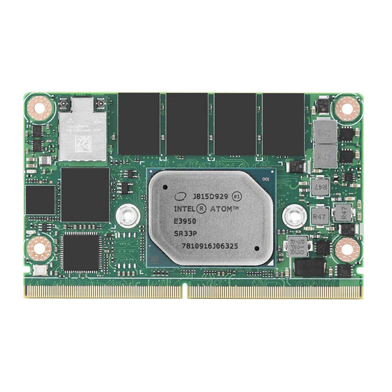
Board Information The figures below indicate the main chips on SOM-2569 Computer-on-Module. Please aware on these positions while design customer’s own carrier board to avoid mechanical violence and thermal solutions contacts for best thermal dispassion per- formance. Figure 2.1 Atom_E3900 Board chips identify – Front Figure 2.2 Atom_E3900 Board chips identify –... -
Page 25: Mechanical Diagram
Mechanical Diagram For more detail about 2D/3D models, please refer to the Advantech COM support service website http://com.advantech.com. Figure 2.3 Atom_E3900 Board Mechanical Diagram - Front Figure 2.4 Atom_E3900 Board Mechanical Diagram – Rear Figure 2.5 Atom_E3900 Board Mechanical Diagram – Side1 Figure 2.6 Atom_E3900 Board Mechanical Diagram –... - Page 26 Figure 2.7 Pentium_Celeron_N_J Series Board Mechanical Diagram – Front Figure 2.8 Pentium_Celeron_N_J Series Board Mechanical Diagram – Rear Figure 2.9 Pentium_Celeron_N_J Series Board Mechanical Diagram – Side1 Figure 2.10 Pentium_Celeron_N_J Series Board Mechanical Diagram – Side2 SOM-2569 User Manual...
-
Page 27: Assembly Diagram
These figures demonstrate the oder of assembly for the thermal module, COM module to carrier board. Figure 2.11 Assembly Diagram There are 4 reserved screw holes for SOM-2569 to be pre-assembled with heat spreader.Please consider the CPU and chip height tolerance when designing your thermal solution. - Page 28 ® Intel Pentium and Celeron N and J Series Processors Figure 2.13 Main Chip Height and Tolerance SOM-2569 User Manual...
-
Page 29: Chapter 3 Ami Bios
Chapter AMI BIOS This chapter details BIOS setup information for the SOM-2569 CPU computer-on module. Sections include: Introduction Entering Setup Hot/Operation Key Exit BIOS Setup Utility... -
Page 30: Introduction
This information is stored in a flash ROM so it retains the Setup information when the power is turned off. Entering Setup Turn on the computer and press <DEL> or <ESC> to enter the Setup menu. SOM-2569 User Manual... -
Page 31: Main Setup
Date using the <Arrow> keys. Enter new values through the keyboard. Press the <Tab> key or the <Arrow> keys to move between fields. The date must be entered in MM/DD/YY format. The time must be entered in HH: MM: SS format. SOM-2569 User Manual... -
Page 32: Advanced Bios Features Setup
Advanced BIOS Features Setup Select the Advanced tab from the SOM-2569 setup screen to enter the Advanced BIOS Setup screen. Users can select any item in the left frame of the screen, such as CPU Configuration, to go to the sub menu for that item. Users can display an Advanced BIOS Setup option by highlighting it using the <Arrow>... -
Page 33: Trusted Computing
Intel ® Anti-Theft Technology Configuration. 3.4.1 Trusted Computing Figure 3.4 Trusted Computing Security Device Support Enables or Disables BIOS support for security device. The OS will not show Security Device. TCG EFI protocol and INT1A interface will not be available. SOM-2569 User Manual... -
Page 34: Acpi Settings
Enables or Disables System ability to Hibernate (OS/S4 Sleep State). This option may be not effective with some OS. ACPI Sleep State Select the highest ACPI sleep state the system will enter when the SUSPEND button is pressed. Lock Legacy Resources Enables or Disables Lock of Legacy Resources. SOM-2569 User Manual... -
Page 35: Embedded Controller
Backlight Control Brightness PWM Polarity for Native or Invert. Power Saving Mode Select power saving Mode. Serial Port 1 Configuration Set parameters of Serial Port 1 (COMA). Serial Port 2 Configuration Set parameters of Serial Port 2 (COMB). Hardware Monitor Monitor hardware status. SOM-2569 User Manual... - Page 36 Serial Port 1 Configuration Figure 3.7 Serial Port 1 Configuration Serial Port Enable or disable Serial Port (COM). Device Settings Set parameters of Serial Port 1 (COMA). Change Settings Select an optimal setting for Super I/O Device. SOM-2569 User Manual...
- Page 37 Serial Port 2 Configuration Figure 3.8 Serial Port 2 Configuration Serial Port Enable or Disable Serial Port (COM). Device Settings Set parameters of Serial Port 2 (COMB). Change Settings Select an optimal setting for Super I/O Device. SOM-2569 User Manual...
-
Page 38: Serial Port Console Redirection
3.4.3.3 Hardware Monitor Figure 3.9 Hardware Monitor 3.4.4 Serial Port Console Redirection Figure 3.10 Serial Port console Redirection COM1 Console Redirection Console Redirection Enable or Disable. SOM-2569 User Manual... - Page 39 Console Redirection Enable or Disable. Console Redirection Settings Theses settings specify how the host computer and the remote computer (which the user is using) will exchange data. Both computers should have the same or compati- ble settings. SOM-2569 User Manual...
-
Page 40: Cpu Configuration
Active Processor Cores Number of cores to enable in each processor package. Intel Virtualization Technology When enabled, a VMM can utilize the additional hardware capabilities provided by Vanderpool Technology. VT-d Enable/Disable CPU VT-d. Monitor Mwait Enable/Disable Monitor Mwait. SOM-2569 User Manual... - Page 41 When Hyper-threading is enabled, 2 logical CPUs per core are present. Intel VT-x Technology CPU VMX hardware support for virtual machines. L1 Data Cache L1 Data Cache Size. L1 Code Cache L1 Code Cache Size. L2 Cache L2 Cache Size. L3 Cache L3 Cache Size. SOM-2569 User Manual...
- Page 42 Figure 3.13 CPU Power Management EIST Enable/Disable Intel SpeedStep. Turbo Mode Turbo Mode. Boot performance mode Select the performance state that the BIOS will set before OS handoff. C-States Enable/Disable C States. Power Limit 1 Enable Enable/Disable Power Limit 1. SOM-2569 User Manual...
-
Page 43: Network Stack Configuration
3.4.6 Network Stack Configuration Figure 3.14 Network Stack Configuration Network Stack Enable/Disable UEFI Network Stack. SOM-2569 User Manual... -
Page 44: Csm Configuration
Controls the execution of UEFI and Legacy PXE OpROM. Storage Controls the execution of UEFI and Legacy Storage OpROM. Video Controls the execution of UEFI and Legacy Video OpROM. Other PCI devices Determines OpROM execution policy for devices other than Network, Storage, or Video. SOM-2569 User Manual... -
Page 45: Nvme Configuration
3.4.8 NVMe Configuration Figure 3.16 NVMe Configuration SOM-2569 User Manual... -
Page 46: Sdio Configuration
SDIO Access Mode Auto Option: Access SD device in DMA mode if the controller supports it, otherwise in PIO mode.DMA Option: Access SD device in DMA mode.PIO Option: Access SD device in PIO mode. MMC – G4032 SOM-2569 User Manual... -
Page 47: Usb Configuration
'Auto' uses default value: for a Root port it is 100 ms, for a Hub port the delay is taken from Hub descriptor. Device power-up delay in seconds Delay range is 1 ~ 40 seconds, in one second increments. SOM-2569 User Manual... -
Page 48: Security Configuration
3.4.11 Security Configuration Figure 3.19 Security Configuration TXE HMRFPO TXE EOP Message Send EOP Message Before Enter OS. SOM-2569 User Manual... -
Page 49: Chipset Setup
Chipset Setup Figure 3.20 Chipset Setup North Bridge North Bridge Parameters. South Bridge South Bridge Parameters. Uncore Configuration Uncore Configuration. South Cluster Configuration South Cluster Configuration. SOM-2569 User Manual... -
Page 50: North Bridge
Memory in the slot. Memory Slot2 Memory in the slot. Memory Slot3 Memory in the slot. Above 4GB MMIO BIOS assignment Enable/Disable above 4GB Memory Mapped I/O BIOS assignment. This is disabled automatically when Aperture Size is set to 2048MB. SOM-2569 User Manual... -
Page 51: South Bridge
3.5.2 South Bridge Figure 3.22 South Bridge Serial IRQ Mode Configure Serial IRQ Mode. SOM-2569 User Manual... -
Page 52: Uncore Configuration
Color depth and packing format. Dual LVDS mode Dual LVDS mode. LCD Panel Type Select LCD panel used by Internal Graphics Device by selecting the appropriate setup item. Enable Image Processing Unit function. (IPC: A processor analyzes and modifies input images). SOM-2569 User Manual... -
Page 53: South Cluster Configuration
HD-Audio Configuration Settings. PCI Express Configuration PCI Express Configuration Settings. SATA Drives Press <Enter> to select the SATA Device Configuration Setup options. SCC Configuration SCC Configuration Settings. USB Configuration USB Configuration Settings. Miscellaneous Configuration Enable/Disable Misc. Features. SOM-2569 User Manual... - Page 54 3.5.4.1 HD-Audio Configuration Figure 3.25 HD-Audio Configuration HD-Audio Support Enable/Disable HD-Audio Support. SOM-2569 User Manual...
- Page 55 PCIe root port. PCI Express Root Port 3 /LANO Control the PCI Express Root Port. AUTO: To disable unused root port automatically for the most optimum power savings. Enable: Enable PCIe root port Disable: Disable PCIe root port. SOM-2569 User Manual...
- Page 56 Control the PCI Express Root Port. AUTO: To disable unused root port automatically for the most optimum power savings. Enable: Enable PCIe root port Disable: Disable PCIe root port. ASPM PCI Express Active State Power Management settings. PCIe Speed Configure PCIe Speed. SOM-2569 User Manual...
- Page 57 Control the PCI Express Root Port. AUTO: To disable unused root port automatically for the most optimum power savings. Enable: Enable PCIe root port Disable: Disable PCIe root port. ASPM PCI Express Active State Power Management settings. PCIe Speed Configure PCIe Speed. SOM-2569 User Manual...
- Page 58 Control the PCI Express Root Port. AUTO: To disable unused root port automatically for the most optimum power savings. Enable: Enable PCIe root port Disable: Disable PCIe root port. ASPM PCI Express Active State Power Management settings. PCIe Speed Configure PCIe Speed. SOM-2569 User Manual...
- Page 59 Control the PCI Express Root Port. AUTO: To disable unused root port automatically for the most optimum power savings. Enable: Enable PCIe root port Disable: Disable PCIe root port. ASPM PCI Express Active State Power Management settings. PCIe Speed Configure PCIe Speed. SOM-2569 User Manual...
- Page 60 Control the PCI Express Root Port. AUTO: To disable unused root port automatically for the most optimum power savings. Enable: Enable PCIe root port Disable: Disable PCIe root port. ASPM PCI Express Active State Power Management settings. PCIe Speed Configure PCIe Speed. SOM-2569 User Manual...
- Page 61 Control the PCI Express Root Port. AUTO: To disable unused root port automatically for the most optimum power savings. Enable: Enable PCIe root port Disable: Disable PCIe root port. ASPM PCI Express Active State Power Management settings. PCIe Speed Configure PCIe Speed. SOM-2569 User Manual...
- Page 62 Determines how SATA controller(s) operate. SATA Controller Speed Indicates the maximum speed the SATA controller can support. SATA Port 0 Port 0 Enable or Disable SATA Port. SATA Port 1 Port 1 Enable or Disable SATA Port. SOM-2569 User Manual...
- Page 63 3.5.4.4 SCC Configuration Figure 3.34 SCC Configuration SCC SD Card Support (D27:F0) Enable/Disable SCC SD card support. SCC eMMC Support (D28:F0) Enable/Disable SCC eMMC support. eMMC Max Speed Select the eMMC max speed allowed. SOM-2569 User Manual...
- Page 64 Once disabled, XHCI controller would be function disabled, none of the USB devices are detectable and usable during boot and in OS. Do not disable it unless for debug- ging purposes. XDCI Support Enable/Disable XDCI. USB HW MODE AFE Comparators Enable/Disable USB HW MODE AFE comparators. SOM-2569 User Manual...
- Page 65 Wake On Lan Enable or Disable the Wake on Lan. BIOS Lock Enable/Disable the SC BIOS Lock Enable feature. Required to be enabled to ensure SMM protection of flash. SOM-2569 User Manual...
-
Page 66: Security Chipset
Security Chipset Figure 3.37 Security Chipset Setup Administrator Password Set Setup Administrator Password. User Password Set User Password. SOM-2569 User Manual... -
Page 67: Boot Setup
Select the keyboard NumLock state. Quiet Boot Enables or disables Quiet Boot option. Boot Option Priorities Boot Option #1 Sets the system boot order Fast Boot Enable or Disable FastBoot features. Most probes are skipped to reduce time cost during boot. SOM-2569 User Manual... -
Page 68: Save & Exit
Save the changes done so far as User Defaults. Restore User Defaults Restore the User Defaults to all the setup options. Boot Override Launch EFI Shell from file system device Attempts to Launch EFI Shell application (Shell.efi) from one of the available filesys- tem devices. SOM-2569 User Manual... -
Page 69: Chapter 4 S/W Introduction & Installation
Chapter S/W Introduction & Installation S/W Introduction Driver Installation Advantech iManager (SUSI 4) -
Page 70: S/W Introduction
S/W Introduction The mission of Advantech Embedded Software Services is to "Enhance quality of life with Advantech platforms and Microsoft Windows embedded technology." We enable Windows Embedded software products on Advantech platforms to more effectively support the embedded computing community. Customers are freed from the hassle of dealing with multiple vendors (Hardware suppliers, System integrators, Embedded OS distributor) for projects. -
Page 71: Advantech Imanager
It makes these embedded features easier to integrate, speed up develop- ing schedule, and provide the customer’s software continuity while upgrade hard- ware. For more details on how to use the APIs and utilities, please refer to Advantech iManager 2.0 Software API User Manual. - Page 72 SOM-2569 User Manual...
-
Page 73: Appendix A Pin Assignment
Appendix Pin Assignment This appendix details information on the hardware pin assignment of the SOM-2569 CPU System on Module. Sections include: SOM-2569 Pin Assignment... -
Page 74: Som-2569 Pin Assignment
SOM-2569 Pin Assignment This section details SOM-2569 pin assignments on SMARC connectors compliant with SMARC 2.0/SMARC 2.1 definitions. For further details on pins usage, or to find design reference materials, please contact to Advantech for design guides, check- lists, reference schematics, and other hardware/software support. - Page 75 GPIO2 / CAM0_RST# P111 GPIO3 / CAM1_RST# I²C_CAM0_DAT I²C_CAM0_CK I²C_CAM1_DAT I²C_CAM1_CK CSI0_RX0+ CSI0_RX0- CSI0_RX1+ CSI0_RX1- CSI1_RX0+ CSI1_RX0- CSI1_RX1+ CSI1_RX1- CSI1_RX2+ CSI1_RX2- CSI1_RX3+ CSI1_RX3- CSI0_CK+ CSI0_CK- CSI1_CK+ CSI1_CK- CAM_MCK SDIO_D0 SDIO_D1 SDIO_D2 SDIO_D3 SDIO Card SDIO_CMD SDIO_CK SDIO_WP SDIO_CD# SDIO_PWR_EN SOM-2569 User Manual...
- Page 76 I²C_GP_DAT P129 SER0_TX P130 SER0_RX P134 SER1_TX P135 SER1_RX P136 SER2_TX P137 SER2_RX Serial Ports P140 SER3_TX P141 SER3_RX P131 SER0_RTS# P132 SER0_CTS# P138 SER2_RTS# P139 SER2_CTS# P143 CAN0_TX P145 CAN1_TX CAN Bus P144 CAN0_RX P146 CAN1_RX SOM-2569 User Manual...
- Page 77 USB0+ USB0- USB1+ USB1- USB2+ USB2- USB3+ USB3- USB4+ USB4- USB5+ USB5- USB0_EN_OC# USB1_EN_OC# USB2_EN_OC# USB3_EN_OC# USB4_EN_OC# USB5_EN_OC# USB0_VBUS_DET USB3_VBUS_DET USB0_OTG_ID S104 USB3_OTG_ID USB2SSRX- USB2SSRX+ USB3SSRX- USB3SSRX+ USB2SSTX- USB2SSTX+ USB3SSTX- USB3SSTX+ SOM-2569 User Manual...
- Page 78 PCIE_A_TX+ PCIE_A_TX- PCIE_B_TX+ PCIE_B_TX- PCIE_C_TX+ PCIE_C_TX- PCIE_D_TX+ PCIE_D_TX- PCIE_A_RX+ PCIE_A_RX- PCIE_B_RX+ PCIE_B_RX- PCIE_C_RX+ PCIe PCIE_C_RX- PCIE_D_RX+ PCIE_D_RX- PCIE_A_REFCK+ PCIE_A_REFCK- PCIE_B_REFCK+ PCIE_B_REFCK- PCIE_C_REFCK+ PCIE_C_REFCK- PCIE_A_RST# PCIE_B_RST# PCIE_C_RST# S146 PCIE_WAKE# SATA_TX+ SATA_TX- SATA SATA_RX+ SATA_RX- SATA_ACT# SOM-2569 User Manual...
- Page 79 GPIO0 / CAM0_PWR# P109 GPIO1 / CAM1_PWR# P110 GPIO2 / CAM0_RST# P111 GPIO3 / CAM1_RST# P112 GPIO4 / HDA_RST# P113 GPIO5 / PWM_OUT GPIO P114 GPIO6 / TACHIN P115 GPIO7 P116 GPIO8 P117 GPIO9 P118 GPIO10 P119 GPIO11 SOM-2569 User Manual...
- Page 80 S153 CARRIER_STBY# P126 RESET_OUT# P127 RESET_IN# P128 POWER_BTN# S149 SLEEP# Management Pins S148 LID# S156 BATLOW# P122 I²C_PM_DAT P121 I²C_PM_CK S151 CHARGING# S152 CHARGER_PRSNT# S157 TEST# SMB_ALERT_1V8# P123 BOOT_SEL0# P124 BOOT_SEL0# Boot Select P125 BOOT_SEL2# S155 FORCE_RECOV# SOM-2569 User Manual...
- Page 81 S147 VDD_RTC P147 VDD_IN P148 VDD_IN P149 VDD_IN P150 VDD_IN P151 VDD_IN P152 VDD_IN P153 VDD_IN P154 VDD_IN P155 VDD_IN P156 VDD_IN P100 P103 P120 P133 Power / GND /RSVD P142 SOM-2569 User Manual...
- Page 82 VDD_JTAG_IO JTAG_TRST# JTAG_TMS JTAG JTAG_TDO JTAG_TDI JTAG_TCK SOM-2569 User Manual...
-
Page 83: Appendix B Watchdog Timer
Appendix Watchdog Timer This appendix details information on the watchdog timer program- ming on the SOM-2569 CPU Sys- tem on Module. Sections include: Watchdog Timer Programming... -
Page 84: Programming The Watchdog Timer
** WDT new driver support automatic select available IRQ number from BIOS, and then set to EC. Only Win10 supports it. In other OS, it will still use IRQ number from BIOS setting as usual. For details, please refer to iManager & Software API User Manual. SOM-2569 User Manual... -
Page 85: Appendix C System Assignments
Appendix System Assignments This appendix details informa- tion on system resource alloca- tion for the SOM-2569 CPU System on Module. Sections include: System I/O ports DMA Channel Assignments Interrupt Assignments 1 MB Memory Map... -
Page 86: System I/O Ports
Programmable interrupt controller 0x000000B0-0x000000B1 Programmable interrupt controller 0x000000B4-0x000000B5 Programmable interrupt controller 0x000000B8-0x000000B9 Programmable interrupt controller 0x000000BC-0x000000BD Programmable interrupt controller 0x000004D0-0x000004D1 Programmable interrupt controller ® ® ® Intel Celeron / Pentium Processor PCI Express Root 0x0000C000-0x0000CFFF Port - 5AD7 SOM-2569 User Manual... - Page 87 PCI Express Root Complex ® ® ® 0x0000F040-0x0000F05F Intel Celeron / Pentium Processor SMBUS - 5AD4 ® ® ® Intel Celeron / Pentium Processor PCI Express Root 0x0000D000-0x0000DFFF Port - 5AD6 0x00000040-0x00000043 System timer 0x00000050-0x00000053 System timer SOM-2569 User Manual...
-
Page 88: Interrupt Assignments
I210 Gigabit Network Connection #3 ® IRQ 4294967278 Intel I210 Gigabit Network Connection #3 ® IRQ 4294967277 Intel I210 Gigabit Network Connection #3 ® IRQ 4294967276 Intel I210 Gigabit Network Connection #3 ® IRQ 4294967275 Intel I210 Gigabit Network Connection #3 SOM-2569 User Manual... - Page 89 Microsoft ACPI-Compliant System IRQ 87 Microsoft ACPI-Compliant System IRQ 88 Microsoft ACPI-Compliant System IRQ 89 Microsoft ACPI-Compliant System IRQ 90 Microsoft ACPI-Compliant System IRQ 91 Microsoft ACPI-Compliant System IRQ 92 Microsoft ACPI-Compliant System IRQ 93 Microsoft ACPI-Compliant System SOM-2569 User Manual...
- Page 90 Microsoft ACPI-Compliant System IRQ 135 Microsoft ACPI-Compliant System IRQ 136 Microsoft ACPI-Compliant System IRQ 137 Microsoft ACPI-Compliant System IRQ 138 Microsoft ACPI-Compliant System IRQ 139 Microsoft ACPI-Compliant System IRQ 140 Microsoft ACPI-Compliant System IRQ 141 Microsoft ACPI-Compliant System SOM-2569 User Manual...
- Page 91 Microsoft ACPI-Compliant System IRQ 183 Microsoft ACPI-Compliant System IRQ 184 Microsoft ACPI-Compliant System IRQ 185 Microsoft ACPI-Compliant System IRQ 186 Microsoft ACPI-Compliant System IRQ 187 Microsoft ACPI-Compliant System IRQ 188 Microsoft ACPI-Compliant System IRQ 189 Microsoft ACPI-Compliant System SOM-2569 User Manual...
- Page 92 Microsoft ACPI-Compliant System IRQ 282 Microsoft ACPI-Compliant System IRQ 283 Microsoft ACPI-Compliant System IRQ 284 Microsoft ACPI-Compliant System IRQ 285 Microsoft ACPI-Compliant System IRQ 286 Microsoft ACPI-Compliant System IRQ 287 Microsoft ACPI-Compliant System IRQ 288 Microsoft ACPI-Compliant System SOM-2569 User Manual...
- Page 93 Microsoft ACPI-Compliant System IRQ 330 Microsoft ACPI-Compliant System IRQ 331 Microsoft ACPI-Compliant System IRQ 332 Microsoft ACPI-Compliant System IRQ 333 Microsoft ACPI-Compliant System IRQ 334 Microsoft ACPI-Compliant System IRQ 335 Microsoft ACPI-Compliant System IRQ 336 Microsoft ACPI-Compliant System SOM-2569 User Manual...
- Page 94 Microsoft ACPI-Compliant System IRQ 378 Microsoft ACPI-Compliant System IRQ 379 Microsoft ACPI-Compliant System IRQ 380 Microsoft ACPI-Compliant System IRQ 381 Microsoft ACPI-Compliant System IRQ 382 Microsoft ACPI-Compliant System IRQ 383 Microsoft ACPI-Compliant System IRQ 384 Microsoft ACPI-Compliant System SOM-2569 User Manual...
- Page 95 Microsoft ACPI-Compliant System IRQ 426 Microsoft ACPI-Compliant System IRQ 427 Microsoft ACPI-Compliant System IRQ 428 Microsoft ACPI-Compliant System IRQ 429 Microsoft ACPI-Compliant System IRQ 430 Microsoft ACPI-Compliant System IRQ 431 Microsoft ACPI-Compliant System IRQ 432 Microsoft ACPI-Compliant System SOM-2569 User Manual...
- Page 96 Microsoft ACPI-Compliant System IRQ 474 Microsoft ACPI-Compliant System IRQ 475 Microsoft ACPI-Compliant System IRQ 476 Microsoft ACPI-Compliant System IRQ 477 Microsoft ACPI-Compliant System IRQ 478 Microsoft ACPI-Compliant System IRQ 479 Microsoft ACPI-Compliant System IRQ 480 Microsoft ACPI-Compliant System SOM-2569 User Manual...
- Page 97 Microsoft ACPI-Compliant System IRQ 505 Microsoft ACPI-Compliant System IRQ 506 Microsoft ACPI-Compliant System IRQ 507 Microsoft ACPI-Compliant System IRQ 508 Microsoft ACPI-Compliant System IRQ 509 Microsoft ACPI-Compliant System IRQ 510 Microsoft ACPI-Compliant System IRQ 511 Microsoft ACPI-Compliant System SOM-2569 User Manual...
-
Page 98: 1St Mb Memory Map
Serial I/O UART Host Controller - 5ABE 0x91410000-0x91413FFF High Definition Audio Controller 0x91000000-0x910FFFFF High Definition Audio Controller ® ® ® 0x91416000-0x914160FF Intel Celeron / Pentium Processor SMBUS - 5AD4 0x91418000-0x91418FFF Intel SD Host Controller 0x91417000-0x91417FFF Intel SD Host Controller SOM-2569 User Manual... - Page 99 USB 3.0 eXtensible Host Controller - 1.0 (Microsoft) ® 0x91220000-0x91223FFF Intel I210 Gigabit Network Connection #3 ® 0x91320000-0x91323FFF Intel I210 Gigabit Network Connection #4 ® 0x9141C000-0x9141CFFF Intel Serial I/O SPI Host Controller - 5AC2 ® 0x9141B000-0x9141BFFF Intel Serial I/O SPI Host Controller - 5AC2 SOM-2569 User Manual...
- Page 100 No part of this publication may be reproduced in any form or by any means, electronic, photocopying, recording or otherwise, without prior written permis- sion of the publisher. All brand and product names are trademarks or registered trademarks of their respective companies. © Advantech Co., Ltd. 2020...
Need help?
Do you have a question about the SOM-2569 and is the answer not in the manual?
Questions and answers