Table of Contents
Advertisement
Quick Links
Advertisement
Table of Contents

Related Manuals for Advantech SOM-6898


Summary of Contents for Advantech SOM-6898
- Page 1 User Manual SOM-6898 COM Express Compact Module...
- Page 2 No part of this manual may be reproduced, copied, translated or transmitted in any form or by any means without the prior written permission of Advantech Co., Ltd. Information provided in this manual is intended to be accurate and reliable. How- ever, Advantech Co., Ltd.
-
Page 3: Declaration Of Conformity
Class I, Division 2, Groups A, B, C and D indoor hazards. Technical Support and Assistance Visit the Advantech website at http://support.advantech.com where you can find the latest information about the product. Contact your distributor, sales representative, or Advantech's customer service center for technical support if you need additional assistance. - Page 4 Before setting up the system, check that the items listed below are included and in good condition. If any item does not accord with the table, please contact your dealer immediately. SOM-6898 CPU module 1 x Heatspreader (1960080159N000) SOM-6898 User Manual...
-
Page 5: Safety Instructions
The sound pressure level at the operator's position according to IEC 704-1:1982 is no more than 70 dB (A). DISCLAIMER: This set of instructions is given according to IEC 704-1. Advantech disclaims all responsibility for the accuracy of any statements contained herein. - Page 6 Don't touch any components on the CPU card or other cards while the PC is on. Disconnect power before making any configuration changes. The sudden rush of power as you connect a jumper or install a card may damage sensitive elec- tronic components. SOM-6898 User Manual...
-
Page 7: Table Of Contents
Figure 3.16Serial Port 3 Configurations........31 Figure 3.17Serial Port 4 Configurations........32 Figure 3.18Parallel Port Configuration........33 Figure 3.19Serial Port Console Redirection ....... 34 Figure 3.20Legacy Console Redirection Settings....... 35 Figure 3.21Network Stack Configuration ........36 Figure 3.22CSM Configuration ........... 37 SOM-6898 User Manual... - Page 8 4.2.1 Windows Driver Setup ..............62 4.2.2 Other OS..................62 Advantech iManager ................63 Appendix A Assignment......... 65 SOM-6898 Type 6 Pin Assignment............66 Appendix B Watchdog Timer........ 71 Programming the Watchdog Timer ............72 Appendix C Programming GPIO......73 GPIO Register..................
-
Page 9: Chapter 1 General Information
Chapter General Information This chapter gives background information on the SOM-6898 CPU Computer on Module. Sections include: Introduction Specification Functional Block Diagram... -
Page 10: Introduction
Introduction SOM-6898 is a COM Express Compact module with type 6 pin-out that fully complies with the PICMG (PCI Industrial Computer Manufactures Group) COM.0 R2.1 specifi- cation. The CPU module uses an Intel 7th Generation Core i processor and other peripheral chips in a basic size 95x95mm COM Express form factor. -
Page 11: Display
PCI Express x1: Supports default 5 ports PCIe x1 compliant. To PCIe Gen3* (8.0 GT/s) specification, several configurable combinations may need BIOS modifies. Please contact Advantech sales or FAE for more detail. (PCIe x1 Port #7 option with SATA2) Default... -
Page 12: I/O
AT: +8.5~20V – CMOS Battery: +3.3V Power Requirement: – Test condition: SOM-6898C7-U8A1E (i7-7600U), ADVANTECH 16GB SO- DDR4-2133 I-GRD 2PCS, Windows 10 Pro, rated voltage DC +5.0V, +12.0V, +20.0V – Idle: 4.16W – Max: 24.61W (BurnIn Test V8.1 Pro (1016) for 64 bit Windows) ... -
Page 13: Functional Block Diagram
2 x SATA3 (SATA0 ~ SATA1)* 4 x USB3.0 6 x PCIEx1 (PCIE0 ~ PCIE5) 1 x PCIEx1 Giga LAN eMMC (Optional) LPC BUS TPM2.0 * Default Setting WDT / GPIO* / I RS1/ RS2/ FAN GPIO SMBus SPI Bus SPI BIOS SOM-6898 User Manual... - Page 14 SOM-6898 User Manual...
-
Page 15: Chapter 2 Mechanical Information
Chapter Mechanical Information This chapter gives mechanical information on the SOM-6898 CPU Computer on Module. Sections include: Board Information Mechanical Drawing Assembly Drawing... -
Page 16: Board Information
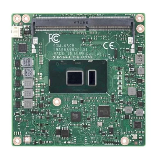
Board Information The figures below indicate the main chips on SOM-6898 Computer-on-Module. Be aware of these positions when designing your own carrier board to avoid mechanical issues, as well as designing a thermal solution with contact points for the best ther- mal dissipation performance. -
Page 17: Mechanical Drawing
Mechanical Drawing For more details about 2D/3D models, please look on the Advantech COM support service website http://com.advantech.com. 87.2 81.3 48.6 Figure 2.3 Board Mechanical Drawing - Front 87.2 83.5 31.7 Figure 2.4 Board Mechanical Drawing - Back SOM-6898 User Manual... -
Page 18: Assembly Drawing
Option 2 NOM: 0.537, TOL: ±0.07 F4=Option1 NOM: 0.852, TOL: ±0.072 Option 2 NOM: 0.952, TOL: ±0.072 F5=Option1 NOM: 1.08, TOL: ±0.092 Option 2 NOM: 1.18, TOL: ±0.092 (POST SMT STACKUP HEIGHT BASED ON LIMITED DATA FROM INTEL REFERENCE BOARD DESIGN) SOM-6898 User Manual... -
Page 19: Figure 2.6 Main Chip Height And Tolerance (Gt2)
Figure 2.6 Main Chip Height and Tolerance (GT2) F5= NOM: 1.213, TOL: ±0.108 (PRE SMT PACKAGE HEIGHT) NOM: 1.16, TOL: ±0.108 (POST SMT STACKUP HEIGHT BASED ON LIMITED DATA FROM INTEL REFERENCE BOARD DESIGN) Figure 2.7 Main Chip Height and Tolerance (GT3) SOM-6898 User Manual... - Page 20 SOM-6898 User Manual...
-
Page 21: Chapter 3 Bios Operation
Chapter BIOS Operation This chapter gives BIOS setup information for the SOM-6898 CPU Computer on Module. Sections include: Introduction Entering Setup Hot / Operation Key Exit BIOS Setup Utility... -
Page 22: Figure 3.1 Setup Program Initial Screen
Figure 3.1 Setup program initial screen AMI's BIOS ROM has a built-in Setup program that allows users to modify the basic system configuration. This information is stored in flash ROM so it retains setup infor- mation when the power is turned off. SOM-6898 User Manual... -
Page 23: Entering Setup
Use this option to change the system time and date. Highlight System Time or System Date using the <Arrow> keys. Enter new values through the keyboard. Press the <Tab> key or the <Arrow> keys to move between fields. - System Date: mm/dd/yyyy - System Time: hh/mm/ss SOM-6898 User Manual... -
Page 24: Advanced Bios Features Setup
3.1.2 Advanced BIOS Features Setup Select the Advanced tab from the SOM-6898 setup screen to enter the Advanced BIOS Setup screen. Users can select any item in the left frame of the screen, such as CPU Configuration, to go to the sub menu for that item. Users can display an Advanced BIOS Setup option by highlighting it using the <Arrow>... - Page 25 Number of cores to enable in each processor package. Hyper-Threading Enabled for Windows XP and Linux (OS optimized for Hyper-Threading Tech- nology) and Disabled for other OS (OS not optimized for Hyper-Threading Tech- nology) Enable/Disable AES (Advanced Encryption Standard) SOM-6898 User Manual...
-
Page 26: Figure 3.4 Power & Performance
3.1.2.2 Power & Performance Figure 3.4 Power & Performance CPU- Power Management Control CPU- Power Management Control Options GT- Power Management Control GT- Power Management Control Options SOM-6898 User Manual... -
Page 27: Figure 3.5 Cpu- Power Management Control
Enable/Disable processor Turbo Mode (requires EMTTM enabled too. AUTO means enabled, unless max turbo ratio is bigger than 16- SKL A0 W/A – C state Enable/Disable CPU Power Management. Allows CPU to go to C states when it’s not 100% utilized. SOM-6898 User Manual... -
Page 28: Figure 3.6 Gt- Power Management Control
GT- Power Management Control Figure 3.6 GT- Power Management Control – RC6 (Render Standby) Check to enable render standby support. SOM-6898 User Manual... - Page 29 3.1.2.3 PCH-FW Configuration ME State Sets ME to soft temporary disabled. Firmware Update Configuration Configures management engine technology parameters. PTT Configuration Configure PTT SOM-6898 User Manual...
-
Page 30: Figure 3.7 Firmware Update Configuration
Firmware Update Configuration Figure 3.7 Firmware Update Configuration – Me FW Image Re-Flash Enable/Disable Me FW Image Re-Flash function SOM-6898 User Manual... -
Page 31: Figure 3.8 Ptt Configuration
1.2- Disables PTT in SkuMgr Warning! PTT/dTPM will be disabled and all data saved on it will be lost. – PTP aware OS Select whether or not the OS you will boot to will be PTP aware. SOM-6898 User Manual... -
Page 32: Figure 3.9 Trusted Computing
3.1.2.4 Trusted Computing Figure 3.9 Trusted Computing Security Device Support Enables or Disables BIOS support for security devices. OS will not show secu- rity device. TCG EFI protocol and INT1A interface will not be available. SOM-6898 User Manual... -
Page 33: Figure 3.10Acpi Settings
Select the highest ACPI sleep state the system will enter when the SUSPEND button is pressed. Lock Legacy Resources Enables or Disables Lock of Legacy Resources S3 Video Repost Enables or Disables Lock of S3 Video Repost SOM-6898 User Manual... -
Page 34: Figure 3.11Imanager Configuration
Power Saving Mode Select Ite8528 Power Saving Mode Serial Port 1 Configuration Set Parameters of Serial Port 1 (COMA) Serial Port 2 Configuration Set Parameters of Serial Port 2 (COMB) Hardware Monitor Monitor hardware status SOM-6898 User Manual... -
Page 35: Figure 3.12Serial Port 1 Configurations
Serial Port 1 Configuration Figure 3.12 Serial Port 1 Configurations – Serial Port Enable or disables serial port (COM). – Change Settings Select an optimal setting for Super IO device. SOM-6898 User Manual... -
Page 36: Figure 3.13Serial Port 2 Configurations
Serial Port 2 Configuration Figure 3.13 Serial Port 2 Configurations – Serial Port Enable or disables. serial port (COM). – Change Settings Selects an optimal setting for Super IO device. SOM-6898 User Manual... -
Page 37: Figure 3.14Hardware Monitor
Hardware Monitor Figure 3.14 Hardware Monitor – Hardware Monitor Information This item shows Hardware information parameters. SOM-6898 User Manual... -
Page 38: Figure 3.15W83627Dhgsec Super Io Configuration
Figure 3.15 W83627DHGSEC Super IO Configuration Serial Port 3 Configuration Set Parameters of Serial Port 3 Serial Port 4 Configuration Set Parameters of Serial Port 4 Parallel Port Configuration Set Parameters of Parallel Port (LPT/LPTE) SOM-6898 User Manual... -
Page 39: Figure 3.16Serial Port 3 Configurations
Serial Port 3 Configuration Figure 3.16 Serial Port 3 Configurations – Serial Port Enable or disables serial port (COM). – Change Settings Select an optimal setting for Super IO device. SOM-6898 User Manual... -
Page 40: Figure 3.17Serial Port 4 Configurations
Serial Port 4 Configuration Figure 3.17 Serial Port 4 Configurations – Serial Port Enable or disables. serial port (COM). – Change Settings Selects an optimal setting for Super IO device. SOM-6898 User Manual... -
Page 41: Figure 3.18Parallel Port Configuration
Parallel Port Configuration Figure 3.18 Parallel Port Configuration – Parallel Port Enable or Disable Parallel Port (LPT/LPTE) – Change Settings Select an optimal setting for Super IO device. – Device Mode Change the Printer Port mode. SOM-6898 User Manual... -
Page 42: Figure 3.19Serial Port Console Redirection
Console Redirection Enable or Disable – COM3 Console Redirection Console Redirection Enable or Disable – COM4 Console Redirection Console Redirection Enable or Disable – Legacy Console Redirection Settings Legacy Console Redirection Settings – Console Redirection Console Redirection Enable or Disable SOM-6898 User Manual... -
Page 43: Figure 3.20Legacy Console Redirection Settings
Legacy Console Redirection Settings Figure 3.20 Legacy Console Redirection Settings – Legacy Serial Redirection Port Select a COM port to display redirection of Legacy OS and Legacy OPROM Messages SOM-6898 User Manual... -
Page 44: Figure 3.21Network Stack Configuration
3.1.2.9 Network Stack Configuration Figure 3.21 Network Stack Configuration Network Stack Enable/Disable UEFI Network Stack. SOM-6898 User Manual... -
Page 45: Figure 3.22Csm Configuration
Storage Controls the execution of UEFI and legacy storage OpROM. Video Controls the execution of UEFI and legacy video OpROM. Other PCI devices Determines OpROM execution policy for devices other than network, storage, or video. SOM-6898 User Manual... -
Page 46: Figure 3.23Nvme Configuration
3.1.2.11 NVMe Configuration Figure 3.23 NVMe Configuration NVMe Configuration NVMe controller and driver information SOM-6898 User Manual... -
Page 47: Figure 3.24Usb Configuration
Maximum time the device will take before it properly reports itself to the Host Controller. 'Auto' uses default value: for a Root port it is 100ms, for a Hub port the delay is taken from Hub descriptor. SOM-6898 User Manual... -
Page 48: Chipset
3.1.3 Chipset Select the chipset tab from the SOM-6898 setup screen to enter the chipset BIOS Setup screen. You can display a chipset BIOS setup option by highlighting it using the <Arrow> keys. All Plug and Play BIOS setup options are described in this section. -
Page 49: Figure 3.26System Agent (Sa) Configuration
3.1.3.1 System Agent (SA) Configuration Figure 3.26 System Agent (SA) Configuration Memory Configuration Memory Configuration Parameters Graphics Configuration Graphics Configuration Parameters VT-d VT-d capability. SOM-6898 User Manual... -
Page 50: Figure 3.27Memory Configuration
Memory Configuration Figure 3.27 Memory Configuration – Max TOLUD Maximum Value of TOLUD. Dynamic assignment would adjust TOLUD auto- matically based on largest MMIO length of installed graphic controller. SOM-6898 User Manual... -
Page 51: Figure 3.28Graphics Configuration
Select DVMT 5.0 Total Graphic Memory size used by the Internal Graphics Device. – Gfx Low Power Mode This option is applicable for SFF only. – Algorithm HDCP Re-encryption Flow. – PM Support Enable/Disable PM Support. – PAVP Enable Enable/Disable PAVP. SOM-6898 User Manual... -
Page 52: Figure 3.29Pch-Io Configuration
Wake on LAN Enable Enable/Disable integrated LAN to wake the system. Serial IRQ Mode Configure Serial IRQ Mode State After G3 Specify what state to go to when power is re-applied after a power failure (G3 state). SOM-6898 User Manual... -
Page 53: Figure 3.30Pci Express Configuration
PCI Express Root Port 1 settings. – PCI Express Root Port 2 PCI Express Root Port 2 settings. – PCI Express Root Port 3 PCI Express Root Port 3 settings. – PCI Express Root Port 4 PCI Express Root Port 4 settings. SOM-6898 User Manual... -
Page 54: Figure 3.31Pci Express Root Port 0 Configuration
PCI Express Root Port 0 Control the PCI Express Root Port. ASPM Set the ASPM level: Force L0s – Force all links to L0s state. Auto – BIOS auto configure Disable – disable ASPM. PCIe Speed Select PCI Express port speed. SOM-6898 User Manual... -
Page 55: Figure 3.32Pci Express Root Port 1 Configuration
PCI Express Root Port 1 Control the PCI Express Root Port. ASPM Set the ASPM level: Force L0s – Force all links to L0s state. Auto – BIOS auto configure Disable – disable ASPM. PCIe Speed Select PCI Express port speed. SOM-6898 User Manual... -
Page 56: Figure 3.33Pci Express Root Port 2 Configuration
PCI Express Root Port 2 Control the PCI Express Root Port. ASPM Set the ASPM level: Force L0s – Force all links to L0s state. Auto – BIOS auto configure Disable – disable ASPM. PCIe Speed Select PCI Express port speed. SOM-6898 User Manual... -
Page 57: Figure 3.34Pci Express Root Port 3 Configuration
PCI Express Root Port 3 Control the PCI Express Root Port. ASPM Set the ASPM level: Force L0s – Force all links to L0s state. Auto – BIOS auto configure Disable – disable ASPM. PCIe Speed Select PCI Express port speed. SOM-6898 User Manual... -
Page 58: Figure 3.35Pci Express Root Port 4 Configuration
PCI Express Root Port 4 Control the PCI Express Root Port. ASPM Set the ASPM level: Force L0s – Force all links to L0s state. Auto – BIOS auto configure Disable – disable ASPM. PCIe Speed Select PCI Express port speed. SOM-6898 User Manual... -
Page 59: Figure 3.36Sata And Rst Configuration
SATA Mode Selection Determines how SATA controller(s) operate. – SATA Controller Speed Indicates the maximum speed the SATA controller can support. – Port 0 Enable or Disable SATA port – Port 1 Enable or Disable SATA port SOM-6898 User Manual... -
Page 60: Figure 3.37Usb Configuration
USB Configuration Figure 3.37 USB Configuration – XHCI Disable Compliance Mode Options to disable Compliance Mode. Default is False to not disable Compliance Mode. Set TRUE to disable Com- pliance Mode. SOM-6898 User Manual... -
Page 61: Figure 3.38Hd Audio Configuration
HD Audio Configuration Figure 3.38 HD Audio Configuration – HD Audio Control Detection of the HD-Audio device. Disabled= HDA will be unconditionally disabled Enabled= HDA will be unconditionally enabled Auto= HDA will be enabled if present, disabled otherwise. SOM-6898 User Manual... -
Page 62: Figure 3.39Scs Configuration
SCS Configuration Figure 3.39 SCS Configuration – eMMC 5.0 Controller Enable or Disable SCS eMMC 5.0 Controller – eMMC 5.0 HS400 Mode Enable or Disable SCS eMMC 5.0 HS400 Controller SOM-6898 User Manual... -
Page 63: Figure 3.40Sb Porting Configuration
SB Porting Configuration Figure 3.40 SB Porting Configuration – SATA RAID ROM Legacy ROM: Legacy option ROM UEFI Driver: UEFI Raid Driver Both: Run the legacy Option ROM and UEFI driver. SOM-6898 User Manual... -
Page 64: Security Setting
Security Setting Figure 3.41 Security Setup Select Security Setup from the SOM-6898 Setup main BIOS setup menu. All Security Setup options, such as password protection is described in this section. To access the sub menu for the following items, select the item and press <Enter>: Change Administrator / User Password: Select this option and press <ENTER>... -
Page 65: Boot Settings
Enables or disables boot with initialization of a minimal set of devices required to launch active boot option. Has no effect for BBS boot options. New Boot Option Policy Controls the placement of newly detected UEFI boot options. SOM-6898 User Manual... -
Page 66: Save & Exit
Restore Defaults The SOM-6898 automatically configures all setup items to optimal settings when users select this option. Optimal Defaults are designed for maximum system perfor- mance, but may not work best for all computer applications. In particular, do not use... - Page 67 Restore User Defaults Restore the User Defaults to all the setup options Launch EFI Shell from file system device This items attempts to Launch EFI Shell application (Shell.efi) from one of the available file system devices. SOM-6898 User Manual...
- Page 68 SOM-6898 User Manual...
-
Page 69: Installation
Chapter S/W Introduction & Installation Sections include: S/W Introduction Driver Installation Advantech iManager... -
Page 70: S/W Introduction
S/W Introduction The mission of Advantech Embedded Software Services is to "Enhance quality of life with Advantech platforms and Microsoft Windows embedded technology." We enable Windows Embedded software products on Advantech platforms to more effectively support the embedded computing community. Customers are freed from the hassle of dealing with multiple vendors (Hardware suppliers, System integrators, Embedded OS distributor) for projects. -
Page 71: Advantech Imanager
More details of how to use the APIs and utilities, please refer to the Advantech iManager 2.0 Software API User Manual. SOM-6898 User Manual... - Page 72 SOM-6898 User Manual...
-
Page 73: Assignment
Appendix Pin Assignment This appendix gives you the infor- mation about the hardware pin assignment of the SOM-6898 CPU System on Module. Sections include: SOM-6898 Type 6 Pin Assign- ment... -
Page 74: Som-6898 Type 6 Pin Assignment
This section gives SOM-6898 pin assignment on COM Express connector which compliant with COMR.0 R2.1 Type 6 pin-out definitions. More details about how to use these pins and get design reference, please contact to Advantech for design guides, checklists, reference schematics, and other hardware/software support. - Page 75 LVDS_A1- LVDS_B1- LVDS_A2+ LVDS_B2+ LVDS_A2- LVDS_B2- LVDS_VDD_EN LVDS_B3+ LVDS_A3+ LVDS_B3- LVDS_A3- LVDS_BKLT_EN GND (FIXED) GND (FIXED) LVDS_A_CK+ LVDS_B_CK+ LVDS_A_CK- LVDS_B_CK- LVDS_I2C_CK LVDS_BKLT_CTRL LVDS_I2C_DAT VCC_5V_SBY GPI3 VCC_5V_SBY RSVD(KBD_RST# if R472 stuffed) B86 VCC_5V_SBY VCC_5V_SBY PCIE_CLK_REF+ BIOS_DIS1# PCIE_CLK_REF- VGA_RED SOM-6898 User Manual...
- Page 76 A107 VCC_12V B107 VCC_12V A108 VCC_12V B108 VCC_12V A109 VCC_12V B109 VCC_12V A110 GND (FIXED) B110 GND (FIXED) SOM-6898 Row C,D GND (FIXED) GND (FIXED) USB_SSRX0- USB_SSTX0- USB_SSRX0+ USB_SSTX0+ USB_SSRX1- USB_SSTX1- USB_SSRX1+ USB_SSTX1+ GND (FIXED) GND (FIXED) DDI1_CTRLCLK_AUX+ DDI1_CTRLDATA_AUX- RSVD...
- Page 77 PCIE_TX18+ (if R140/R139 stuffed) (if C13/C12 stuffed) PCIE_RX18- PCIE_TX18- (if R140/R139 stuffed) (if C13/C12 stuffed) GND (FIXED) GND (FIXED) PCIE_RX19+ PCIE_TX19+ (if R140/R139 stuffed) (if C13/C12 stuffed) PCIE_RX19- PCIE_TX19- (if R140/R139 stuffed) (if C13/C12 stuffed) RSVD RSVD SOM-6898 User Manual...
- Page 78 GND (FIXED) C101 D101 C102 D102 C103 D103 C104 VCC_12V D104 VCC_12V C105 VCC_12V D105 VCC_12V C106 VCC_12V D106 VCC_12V C107 VCC_12V D107 VCC_12V C108 VCC_12V D108 VCC_12V C109 VCC_12V D109 VCC_12V C110 GND (FIXED) D110 GND (FIXED) SOM-6898 User Manual...
-
Page 79: Watchdog Timer
Appendix Watchdog Timer This appendix gives you the infor- mation about the watchdog timer programming on the SOM-6898 CPU System on Module. Sections include: Watchdog Timer Programming... -
Page 80: Programming The Watchdog Timer
** WDT new driver support automatically selects available IRQ number from BIOS, and then sets EC. Only Win 10 supports it. In other OS, it will still use IRQ number from BIOS setting as usual. For details, please refer to iManager & Software API User Manual: SOM-6898 User Manual... -
Page 81: Programming Gpio
Appendix Programming GPIO This Appendix gives the illustra- tion of the General Purpose Input and Output pin setting. Sections include: System I/O Ports... -
Page 82: Gpio Register
GPIO Register GPIO Byte Mapping H/W Pin Name BIT0 GPO0 BIT1 GPO1 BIT2 GPO2 BIT3 GPO3 BIT4 GPI0 BIT5 GPI1 BIT6 GPI2 BIT7 GPI3 For details, please refer to iManager & Software API User Manual. SOM-6898 User Manual... -
Page 83: System Assignments
Appendix System Assignments This appendix gives you the infor- mation about the system resource allocation on the SOM-6898 CPU System on Module. Sections include: System I/O ports Interrupt Assignments 1st MB Memory Map... -
Page 84: System I/O Ports
Programmable interrupt controller 029C-029D Motherboard resources 02E8-02EF Communications Port (COM4) 02F8-02FF Communications Port (COM2) 0378-037F Printer Port (LPT1) 03E8-03EF Communications Port (COM3) 03F8-03FF Communications Port (COM1) 04D0-04D1 Programmable interrupt controller 0680-069F Motherboard resources 0D00-0FFF PCI Express Root Complex SOM-6898 User Manual... -
Page 85: Interrupt Assignments
– 9D2B IRQ FFFFFFFA(-6) Intel® Management Engine Interface IRQ FFFFFFFB(-5) Intel® USB 3.0 eXtensible Host Controller – 1.0(Microsoft) IRQ FFFFFFFC(-4) Intel® HD Graphics 620 IRQ FFFFFFFD(-3) Intel® Ethernet Connection I219-V IRQ FFFFFFFE(-2) Standard SATA AHCI Controller SOM-6898 User Manual... -
Page 86: 1St Mb Memory Map
0xFE40E000-0xFE40EFFF Intel(R) Management Engine Interface 0xFE40F000-0xFE40FFFF Intel(R) Serial IO UART Host Controller – 9D27 0xFE410000-0xFE7FFFFF Motherboard resources 0xFED00000-0xFED003FF High precision event timer 0xFED10000-0xFED17FFF Motherboard resources 0xFED18000-0xFED18FFF Motherboard resources 0xFED19000-0xFED19FFF Motherboard resources 0xFED20000-0xFED3FFFF Motherboard resources 0xFED45000-0xFED8FFFF Motherboard resources SOM-6898 User Manual... - Page 87 Table D.3: 1st MB Memory Map 0xFED90000-0xFED93FFF Motherboard resources 0xFEE00000-0xFEEFFFFF Motherboard resources 0xFF000000-0xFFFFFFFF Legacy device 0xFF000000-0xFFFFFFFF Motherboard resources SOM-6898 User Manual...
- Page 88 No part of this publication may be reproduced in any form or by any means, electronic, photocopying, recording or otherwise, without prior written permis- sion of the publisher. All brand and product names are trademarks or registered trademarks of their respective companies. © Advantech Co., Ltd. 2017...
Need help?
Do you have a question about the SOM-6898 and is the answer not in the manual?
Questions and answers