Table of Contents
Advertisement
Quick Links
Advertisement
Table of Contents

Subscribe to Our Youtube Channel
Related Manuals for US Water Systems FlexxHD Series


Summary of Contents for US Water Systems FlexxHD Series
- Page 1 US Water Systems FlexxHD Series Water Softener 080-FXHD-XXX...
-
Page 2: Table Of Contents
Table of Contents Unpacking and Inspection ..................3 Safety Guide ...................... 3 Before Starting Installation ..................4 Proper Installation ....................4 Tools, Pipe, Fittings, and Other Materials ............4 System Overview ...................... 5 System Dimensions ....................6 Specifications ......................7 How the Water Softener Works ................. -
Page 3: Unpacking And Inspection
Be sure to check the entire unit for any shipping damage or lost parts. Also note damage to the shipping cartons. Contact US Water Systems at 1-800-608-8792 to report any shipping damage within 24 hours of delivery. Claims made after 24 hours may not be honored. -
Page 4: Before Starting Installation
Before Starting Installation Proper Installation This water softening system must be properly installed and located in accordance with the Installation Instructions before it is used or the warranty will be void. • Do not Install or store where it will be maximum. -
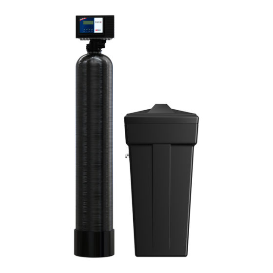
Page 5: System Overview
System Overview Need help? 1.800.390.5936 www.uswatersystems.com... -
Page 6: System Dimensions
System Dimensions Model Tank Size FXHD-075 8" x 44" 50.375" 46.375" 8" FXHD-100 9" x 48" 54.375" 50.875" 9" FXHD-150 10" x 54" 60.375" 57" 10" FXHD-200 12" x 52" 58.625" 55.25" 12" NOTE: The 080-FXHD-075 uses an 11"x11"x34" brine tank Need help? 1.800.390.5936 www.uswatersystems.com... -
Page 7: Specifications
Specifications Model Number FXHD-075 FXHD-100 FXHD-150 FXHD-200 Tank Size 8" x 44" 9" x 48" 10" x 54" 12" x 52" Capacity (cu/ft) 0.75 Maximum Capacity* 27,000 Grains 35,000 Grains 53,000 Grains 70,000 Grains High Efficiency Settings** 11,250 Grains 15,000 Grains 22,500 Grains 30,000 Grains Salt Setting... - Page 8 * Capacity when new ; ** Treating Moderate Hardness only • Continuous operation at flow rates greater than the service flow rate may affect capaci- ty and efficiency performance. • The manufacturer reserves the right to make product improvements which may deviate from the specifications and descriptions stated herein, without obligation to change previously manufactured products or to note the change.
-
Page 9: How The Water Softener Works
How the Water Softener Works Water hardness is derived from Calcium and Magnesium minerals that have been dis- solved into the water under the earth’s surface. These minerals are found in limestone deposits and are the source of hard water. The amount of hardness in a given water supply is dependent upon the quantity of Calcium and Magnesium present and the length of time water has been in contact with them. - Page 10 Backwash - The control valve directs the water flow in a reverse direction through the mineral tank, separating the resin beads and flushing any accumulated particles to a waste drain. Brine & Rinse - In the first part of this cycle, the control valve directs brine sol- ution downward through the mineral tank, driving-off collected hardness ions and replenishing the resin beads with sodium ions.
-
Page 11: Where To Install The Softener
Where to Install the Softener • Place the softener as close as possible to • Put the softener in a place where water the pressure tank (well system) or water damage is least likely to occur if a leak meter (city water). develops. -
Page 12: Softener Preparation
Softener Preparation Softener Tank Preparation Water Pressure: A minimum of 20 pounds of water pressure is required for the regenera- tion valve to operate effectively. Electrical Facilities: An uninterrupted alternating current (AC) supply is required. Note: Other voltages are available. Please make sure your voltage supply is compatible with your unit before installation. - Page 13 Use the blue funnel provided to pour the media into the tank. Pour it evenly around the hole to ensure it is well distributed in the tank and pour slow enough to keep from plugging the hole. A helper may be needed to hold the funnel during the filling process.
- Page 14 Install the upper basket on the bottom of the valve by lining up the tabs then turning the basket clockwise to lock it in place. Place the upper basket over the distributor tube and push the valve onto the tank. Thread the valve on the tank by turning it clockwise.
- Page 15 Tighten the valve hand tight then snug it further by tapping it with the palm of the hand. DO NOT use tools to tighten the valve or damage could occur. Need help? 1.800.390.5936 www.uswatersystems.com...
-
Page 16: Installation Instructions
Installation Instructions If your hot water tank is electric, turn off the power to it to avoid damage to the element in the tank. If you have a private well, turn the power off to the pump and then shut off the main water shut off valve. - Page 17 Be sure to use Teflon tape or other pipe sealant on the plumbing fitting threads and install them on the bypass accordingly. Use an adjustable wrench to ensure they are tight. NOTE: All piping should be secured to prevent stress on the bypass valve and connectors.
- Page 18 Connect the drain hose to the valve and secure it with a hose clamp. Run the drain hose to the nearest laundry tub, floor drain or approved air gap fitting. The drain can be ran overhead or down along the floor. Drain tubing should be a minimum of 1/2" ID.
- Page 19 Connect the brine line to the control valve by removing the blue retaining clip from the brine connection on the control valve. Slide the brine line into the brine tubing port until it is fully seated. Lightly tug on the tubing to ensure it is connected properly then reinstall the blue retaining clip.
- Page 20 Now connect the brine line to the brine tank safety float assembly. Remove the brine tank lid and the brine well cap. There is a red clip on the cap that will be used to hold the brine line in place. Remove it, and the tape holding it, and put it to the side. Then push the brine line through the brine tank and brine well.
- Page 21 Turn the bypass handle so it is perpendicular to the bypass to place the unit in the bypass position. Slowly turn on the main water supply. At the nearest cold treated faucet or spigot, open the faucet and let water run a few minutes or until the system is free of any air or foreign material resulting from the plumbing work.
- Page 22 10. Open the brine tank lid and add 1-2 gallons of water to the brine tank. Add a minimum of 80 lbs of salt to the brine tank. NOTE: Salt should be filled, used completely and refilled. Salt should not be "topped off"...
-
Page 23: System Regeneration
System Regeneration Normal Operation Home Display - The home display will show the time of day set, gallons left until regener- ation, as well as the Regeneration Mode set. The meter will count down to zero and then regenerate at the scheduled time set if the valve is set to Meter Delayed (TM). This is how the valve will come programmed from the factory. -
Page 24: Programming Using Onboard Buttons
Programming Using Onboard Buttons Progamming Time of Day / Hardness / Regeneration Day Override If the valve screen is not currently lit up, pressing the Menu button once will activate it. Press the Menu button again while the valve screen is lit to access programming steps. All steps are done in sequential order I.E. - Page 25 Regeneration Day Override - Press the Menu button until dAY displays and has a value flashing. Press the Regen button and the final number value will begin flashing. Adjust this parameter to every 14 days. If the system will be down more than two weeks at times, set the unit to 10 days.
- Page 26 Regeneration Time - Press the Menu button until rEGE displays and is flashing. Press the Regen button and the number will begin flashing. Adjust the value by pressing the Up and Down buttons until the desired regeneration time for normal operation is shown.
- Page 27 Rapid Rinse - Press the Menu button until RR is displayed in a black box and is flashing. Press the Regen button and the number next to P3 will begin flashing. Adjust the value by pressing the Up and Down buttons until the desired Rapid Rinse time (in minutes) is shown.
-
Page 28: System Start-Up
System Start-Up With the bypass handle in the bypass position, initiate an immediate regeneration. This will advance the valve to the backwash position. Once the valve has stopped moving and is in the backwash position, slowly open the bypass handle about 1/8th turn. Water should slowly enter the tank. NOTE: If there is a loud knocking sound, simply turn the bypass handle back a bit as the system is filling too quickly. -
Page 29: About The System
About The System Safety Float The brine tank is equipped with a safety float which prevents your brine tank from overfill- ing as a result of a malfunction such as a power failure. New Sounds You may notice new sounds as your water softener operates. The regeneration cycle lasts up to 120 minutes. -
Page 30: Maintenance
Maintenance Adding Salt Use only Extra Course Grade or Crystal Solar Salt (99.8% Pure) water softener salt. Check the salt level monthly. It is important to maintain the salt level above the water level. Salt should be filled, used completely, and refilled. Salt should not be “topped off” each month. -
Page 31: Sanitizing Procedure
Sanitizing Procedure Care is taken at the factory to keep your water softener clean and sanitary. Materials used to make the softener will not infect or contaminate your water supply and will not cause bacteria to form or grow. However, during shipping, storage, installing and operating, bacteria could get into the softener. -
Page 32: Warranty
TO PLACE THIS EQUIP- 5 Year Warranty on Media Tank and Brine MENT UNDER WARRANTY, THE WAR- Tank - US Water Systems will replace the RANTY REGISTRATION MUST BE COM- mineral tank or brine tank of the System,... - Page 33 OWNER WITH WRITTEN APPROVAL OF lations. US WATER SYSTEMS AND PAYMENT OF US Water Systems does not authorize any STANDARD TRANSFER FEE. person to assume for us any other obliga- Need help? 1.800.390.5936 www.uswatersystems.com...
Need help?
Do you have a question about the FlexxHD Series and is the answer not in the manual?
Questions and answers