Table of Contents
Advertisement
Quick Links
Visit us online at
www.uswatersystems.com
Escort High Capacity Portable
Owners Manual
Models:
091-EPWS-1, 091-EPWS-2, 091-EPWS-1-CR, 091-EPWS-2-CR
REVISION #
1.1
REVISION DATE May 5, 2016
Water Softener
1. Read all instructions carefully before operation.
2. This system is not intended for treating water that is microbio-
logically unsafe or of unknown quality without adequate disin-
fection before or after the system.
US Water Systems Corporate Office
1209 Country Club Road
Indianapolis, IN 46234
Advertisement
Table of Contents

Subscribe to Our Youtube Channel
Related Manuals for US Water Systems Escort 091-EPWS-1


Summary of Contents for US Water Systems Escort 091-EPWS-1
- Page 1 Owners Manual Models: 091-EPWS-1, 091-EPWS-2, 091-EPWS-1-CR, 091-EPWS-2-CR US Water Systems Corporate Office 1209 Country Club Road REVISION # Indianapolis, IN 46234 REVISION DATE May 5, 2016...
-
Page 2: Table Of Contents
Be sure to check the entire softener for any shipping damage or parts loss. Also note dam- age to the shipping cartons. Contact US Water Systems at 1-800-608-8792 to report any shipping damage within 24 hours of delivery. Claims made after 24 hours may not be hon- ored. -
Page 3: Proper Installation
Proper Installation This water softening system must be properly installed and located in accordance with the Installation Instructions before it is used or the warranty will be void. Do not install or store where it will be Softener resins may degrade in the pres- ... -
Page 4: System Dimensions
System Dimensions MODEL 091-EPWS-1 27” 21 1/2” 7” 26” 14” 7 1/2” 091-DPWS-2 38” 21 1/2” 8” 26” 14” 7 1/2” NOTE: DIMENSION “C” IS ALSO THE SYSTEM DEPTH. Visit us online at www.USWaterSystems.com Give us a call at: 1-800-608-8792... -
Page 5: Before Starting
Before Starting Installation Tools, Pipe, and Fittings, Other Materials Channel Locks Screwdriver Teflon tape Razor knife Two adjustable wrenches Additional tools may be required if modification to the plumbing is required. Power Drill and 7/16” drill bit may be required to convey the regeneration waste line. ... -
Page 6: Before Starting Installation
Before Starting Installation Where To Install The Softener Place the softener as close as possible to Do not install the softener in a place where the feed water source. it could freeze. Damage caused by freez- Place the softener as close as possible to ing is not covered by the warranty. -
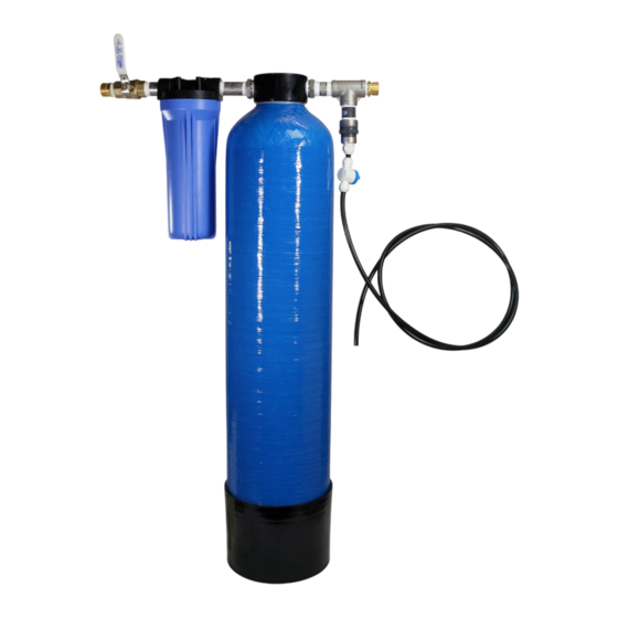
Page 7: Component Identification
Component Identification 2.5 X 10 FILTER HOUSING REGENERATION TANK AND TANK HEAD 5 MICRON FILTER STAND PIPE (D) INTERMEDIATE FEED WATER OUTLET/REGENERATION MANIFOLD (B) MANIFOLD (A) MANIFOLD (C) BACKWASH WHIP HOSE (E) - Page 8 Tank Preparation 1) Remove the resin tank from carton. 2) Verify the riser tube is centered in the bottom center of the tank. A flashlight may be necessary. There is an indentation in the bottom of the tank that will center the dis- tributor tube.
- Page 9 Tank Preparation 4) Use the Blue Funnel provided, to pour the softening resin into the tank. Pour it evenly around the hole to ensure it is well distributed in the tank and pour slow enough, to keep from plugging the hole. A helper may be needed to hold the funnel during the filling process.
-
Page 10: Softener Preparation
Softener Preparation Remove the resin tank and tank head from the packaging. Remove the shipping cap from the resin tank and install the tank head by placing the upper basket over the dis- tributor tube and turning it clockwise until hand tight. BE SURE not to cross-thread the head in the tank. - Page 11 Softener Preparation Install the intermediate manifold (B) in the resin tank “IN” port. Tighten with channel locks. BE SURE not to overtighten the manifold or damage could occur. Remove the sump from the filter housing and install the filter housing head on the in- termediate manifold.
- Page 12 Softener Preparation Install the feed water manifold (A) in the “IN” port on the filter housing head by turning it clockwise. Then snug it further using channel locks. DO NOT overtighten or dam- age could occur. Visit us online at www.USWaterSystems.com Give us a call at: 1-800-608-8792...
- Page 13 Softener Preparation Install the outlet manifold (C) into the “OUT” port on the resin tank head. Turn it clock- wise until hand tight then snug it an additional 1/4 to 1/2 turn with channel locks.
- Page 14 Softener Preparation Install the 5 micron pre-filter in the filter housing sump and install the sump on the filter housing head. Tighten it hand tight, then snug it an additional 1/4 to 1/2 turn with the supplied filter wrench. BE SURE to remove the plastic from the filter. Visit us online at www.USWaterSystems.com Give us a call at: 1-800-608-8792...
-
Page 15: Installation Instructions
Installation Instructions Install the system and secure it in the desired location. Connect the inlet plumbing to the feed water manifold (A). Be sure the connection is tight. Connect the outlet plumbing to the outlet/regeneration manifold (C). -
Page 16: System Start-Up
System Start-Up 1. Open a faucet down stream of the unit and slowly open the inlet valve on the inlet mani- fold (A). Open about 1/4 of a turn and allow the system to SLOWLY fill. 2. Once the system is full, open the inlet valve on the inlet manifold (A) completely. 3. -
Page 17: System Regeneration
System Regeneration The Escort Portable water softener will need to be regenerated periodically. The following process will be used when this is necessary. 091-EPWS-1 (0.3 cu/ft) 091-EPWS-2 (0.7 cu/ft) 3 minutes for brine feed 3 minutes for brine feed twice (6 minutes total) 30 minutes soak time 30 minutes soak time 15 minutes rinse time... - Page 18 System Regeneration Install Regeneration Stand Pipe (D) stand pipe in the filter housing cap. Fill the filter housing sump with 3 lbs of canning salt. Pour about ½ cup of water in the sump to help with installation. Install the sump of salt by forcing the stand pipe through the salt. Tighten the filter sump and be sure not to cross thread it.
- Page 19 System Regeneration Open the 0.5 GPM restricted regeneration valve Open the water supply valve and allow the system to run through the 0.5 GPM restricted regeneration valve for 3 mins. NOTE: DO NOT run longer than 3 mins for each sump full of salt or over dilution may occur. The larger system (0.7 cu/ft) will require two sumps full (6 lbs) of salt for regeneration.
- Page 20 System Regeneration Install a new or rinsed used filter back in the filter sump and install the filter sump on the filter cap. Tight- en it hand tight and an additional ¼ to ½ turn. After 30 mins of soak time, open the feed water valve and allow the system to rinse through the restrict- ed regeneration valve.
-
Page 21: System Backwash
System Backwash Close the inlet valve on the main water source. Open a valve downstream to release any pressure on the system. Close the valve on the inlet manifold (A). Detach the inlet and outlet plumbing connections on the system and rotate the system 180 degrees. Attach the inlet plumbing to the outlet/regeneration manifold (C) on the system. - Page 22 System Backwash Remove the filter from the 2.5 x 10 housing and put the filter housing sump back on the filter housing. Secure the filter sump with the supplied wrench. Attach the backwash whip hose to inlet manifold (A) and convey it to a drainage point. This will restrict the flow during backwash.
- Page 23 System Backwash Allow the system to backwash for 10 minutes. Close the main water source. Allow the system to stop flowing from the backwash whip hose. Disconnect the inlet connection from the outlet/regeneration manifold (C) on the system. Remove the backwash whip hose. Rotate the system 180 degrees and connect the inlet plumbing to the inlet manifold (A) and the connect the outlet plumbing to the outlet/regeneration manifold (C).
- Page 24 Care of Your System To retain the attractive appearance of your new water softener, clean the outside of the tank occasionally with mild soap solution. Do not use abrasive cleaners, ammonia or solvents. Never subject your softener to freezing or to temperatures above 100°F. If there is iron or other contaminants in the water source, it may be necessary to regenerate with an iron removal chemical periodically.
-
Page 25: Capacity Calculation
Capacity Calculation To treat the water properly, the contaminant levels will need to be known to determine the amount of gallons that can be used between regeneration cycles. The supplied hardness test strips can be used to determine the feed water hardness level. Once that is known, there is a calculation that will determine the number of gallons that can be treated. -
Page 26: Warranty
Five Year Tank Head and Other Parts US Water Systems will replace the tank head and other parts if one of them fails within five years from date of manufacture, provided the failure is due to a defect in material or workmanship.
Need help?
Do you have a question about the Escort 091-EPWS-1 and is the answer not in the manual?
Questions and answers