Table of Contents
Advertisement
Visit us online at
www.uswatersystems.com
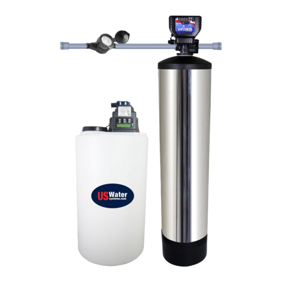
US Water Matrixx inFusion Iron and Sul-
Models:
081-IF-XXX
REVISION #
1.1
REVISION DATE
December 4, 2018
fur Removal System
Owners Manual
US Water Systems, Inc.
1209 Country Club Road
Indianapolis, IN 46234
US Water Systems Corporate Office
info@uswatersystems.com
1209 Country Club Road
www.uswatersystems.com
Indianapolis, IN 46234
info@uswatersystems.com
REVISION 1.5, 10-31-14
www.uswatersystems.com
1-800-608-8792
1-800-608-8792
Advertisement
Table of Contents

Subscribe to Our Youtube Channel
Related Manuals for US Water Systems Matrixx inFusion 081-IF Series


Summary of Contents for US Water Systems Matrixx inFusion 081-IF Series
- Page 1 US Water Matrixx inFusion Iron and Sul- fur Removal System Owners Manual US Water Systems, Inc. 1209 Country Club Road Indianapolis, IN 46234 Models: 1-800-608-8792 081-IF-XXX US Water Systems Corporate Office info@uswatersystems.com 1209 Country Club Road www.uswatersystems.com Indianapolis, IN 46234 info@uswatersystems.com REVISION 1.5, 10-31-14 www.uswatersystems.com 1-800-608-8792...
-
Page 2: Table Of Contents
Be sure to check the entire system for any shipping damage or parts loss. Also note damage to the shipping cartons. Contact US Water Systems at 1-800-608-8792 to report any shipping damage within 24 hours of de- livery. Claims made after 24 hours may not be honored. -
Page 3: Proper Installation
Proper Installation This water filtering system must be properly installed and located in accordance with the Installation Instructions before it is used or the warranty will be void. Do not install or store where it will be ex- sweat-solder connections, as required by •... -
Page 4: System Overview And Specifications
System is the answer to practically any iron, rust, sulfur or hydrogen sulfide problem, and is backed with our 90-Day 100% Satisfaction Guarantee. US Water Systems guarantees 100% iron and sulfur removal with its Matrixx InFusion System which utilizes Hydrogen Peroxide or H2O2. -
Page 5: How The Matrixx Infusion Treatment System Works
4-5 days. The typical frequency is 1-3 days. Contact US Water Systems and a Certified Water Specialist will be able to determine the frequency that can be used when considering the feed water contaminant levels. The factory... -
Page 6: Matrixx Installation Instructions And Specifications
Matrixx Installation Instructions and Specifications WATER PRESSURE: A minimum of 20 pounds of water pressure is required for regenera- tion valve to operate effectively. ELECTRICAL FACILITIES: An uninterrupted alternating current (A/C) supply is re- quired. Note: Other voltages are available. Please make sure the voltage supply is com- patible with the unit before installation. -
Page 7: Infusion Tank And Control Valve Preparation
InFusion Tank and Control Valve Preparation 1. Lubricate the distributor O-ring and the outer tank O-ring. 2. Install the upper basket on the bottom of the valve by lining up the tabs then turning the basket clockwise to lock it in place. Place the upper basket over the distributor tube and push the valve on the tank. -
Page 8: Water Meter Installation
Water Meter Installation Instructions 1. After the sediment filter, install the water meter. There is a flow direction arrow on the meter. Be sure the inlet plumbing is attached to the meter correctly. There should be 18” of hori- zontal pipe before and after the water meter to ensure it is reading properly. 2. - Page 9 Water Meter Installation Instructions 4. Slide the nut over the outlet nipple and install the outlet nipple in the outlet plumbing. Use Teflon tape to seal the connection and tighten with channel locks. Do no over-tighten the nipple in the outlet plumbing connection or damage could occur. 5.
-
Page 10: Tank And Control Valve Connections
Tank and Control Valve Connections If the hot water tank is electric, turn off the power to it to avoid damage to the element in the tank. If the supply is a private well, turn the power off to the pump and then shut off the main water shut off valve. - Page 11 Tank and Control Valve Connections 5. Connect the drain hose to the valve and secure it with a hose clamp. Run the drain hose to the nearest laundry tub, floor drain or approved air gap fitting. The drain can be ran overhead or down along the floor.
-
Page 12: New Sounds
New Sounds There may be new sounds when the system operates. The Backwash cycle lasts up to 25 minutes. During this time, water can be heard running intermittently to the drain. Automatic Hard Water Bypass During Regeneration The regeneration cycle can last 25 to 30 minutes, after which treated water service will be re- stored. -
Page 13: Chemical Solution Tank With Pump Mounted
Chemical Solution Tank (with Pump) Installation Instructions 1. Install the chemical pump mounting bracket on the solution tank. Center the bracket on the back side of the tank. Install the two longer screws (supplied) in the outer holes. Tighten all screws. - Page 14 Chemical Solution Tank (with Pump) Installation Instructions 2. Install the chemical injection pump on the bracket that was installed on the tank us- ing the screws taped to the bracket. 3. Drill a 1/4” hole in the top of the solution tank and install the tubing into the tank.
- Page 15 Chemical Solution Tank (with Pump) Installation Instructions 4. Install the weighted suction screen on the tubing that was inserted in the tank. Push the tubing down in the tank until the weighted suction screen is around 1” from the bottom of the tank. 5.
- Page 16 Chemical Solution Tank (with Pump) Installation Instructions 6. Install a piece of tubing on the outlet of the pump. Be sure to orient the sleeve properly and hand tighten the nut. The outlet is identified by and arrow that is point- ing away from the pump.
-
Page 17: Chemical Pump Wiring For Tank Mounted System
Chemical Pump Wiring Installation Instructions 1. The wire coming from the previously installed water meter should have three wires. A black, red and blue wire. The blue wire is not used and should be folded back and taped to prevent it from making contact with anything. 2. -
Page 18: Chemical Injection Pump Start-Up Instructions
Chemical Injection Pump Start-up Instructions 1. Plug the chemical pump power cord into a continuously energized 110v outlet. The chemical pump should be set when the unit is shipped. It should be set to “5 SEC- ONDS” and the percentage should be set on 50%. If the injection panel is used go to page 29. -
Page 19: System Regeneration Using Onboard Buttons
System Regeneration Using Onboard Buttons Normal Operation 1. Home Display The home display will alternate between the Time of Day and Gallons left until the next regen- eration. The meter will count down to zero (0000) and then regenerate at the scheduled time set. -
Page 20: Programming Using Onboard Buttons
Programming Using Onboard Buttons 1. To enter Main Menu, press the Menu/Enter button. (Time of Day will flash) 2. To set the Time of Day, press the Set/Change button. (First digit will flash) To change digit value, • press the Set/Change but- ton. -
Page 21: Programming Using Water Logix App
Programming Using Water Logix App US Water Systems has moved into the 21st century with our latest line of equipment that utiliz- es the Water Logix Bluetooth System Control Application for iPhone and Android. This app al- lows the user to control every aspect of the water systems from convenience of a smart phone. - Page 22 Programming Using Water Logix App Dashboard Parameters that can be changed are indicated with orange font. To change a parameter tap on the orange font then use the keyboard that appears to change the value. Time of Day: Tap on the “Time of Day” box. A box will appear that allows you to set the unit to the time that matches the device being used to program the unit.
- Page 23 Programming Using Water Logix App Advanced Settings Parameters that can be changed are indicated with orange font. To change a parameter tap on the orange font then use the keyboard that appears to change the value. Backwash: This should be set to “10” mins and should not be changed. Rest: This should be set to “2”...
- Page 24 Programming Using Water Logix App Status and History The Status and History screen shows current conditions of the system as well as flow rate and usage history. There are two parameters that can be reset; Total Regenerations: This parameter shows how many times the system has regenerat- ed since it was put in service or since the last time the value was reset.
-
Page 25: Contact Information
Contact Information The Contact Information screes is used to provide the customer with contact info for US Water Systems. There is a link to the website and to our support team. Regeneration Initiation There are two options for regenerating the system. Tap on the desired option and press “OK”. -
Page 26: System Start-Up Instructions
System Start-up Instructions 1. Once all the plumbing has been connected, open the main water shutoff valve. 2. Plug the Matrixx valve into an approved power source that is constantly energized. 3. When power is supplied to the control valve, wait for a second while it finds the service posi- tion. -
Page 27: H2O2 Injection Pump Adjustment Instructions (Bubble Method)
Hydrogen Peroxide Injection Rate Adjustment Instructions US Water Systems uses the “bubble method”. This is a visual method that works best for quick and reliable H2O2 injection rates. 1. Set the proportional control on the Stenner injection pump to 50% by holding the “%” button while using the “UP”... -
Page 28: Infusion Carbon Filter Valve Battery Backup
Infusion Carbon Filter Valve Battery Backup Battery Back-Up (Uses a standard 9-volt alkaline battery.) • During power failures, the battery will maintain the time of day as long as the battery has pow- er. The display is turned off to conserve battery power during this time. To confirm that the bat- tery is working, press either button and the display will turn on for five (5) seconds. -
Page 29: What To Expect And Routine Maintenance
If this does occur, it is easily eradicated with a chlorination well “shock” procedure. Ask a US Water Systems representative about our well sanitizing kits. 3. There may be “bubbles” in the water for a few weeks after installation. A few bubbles are fine, but if there is “fizz”... -
Page 30: Maintenance Schedule
Maintenance Schedule Component Action Frequency Existing Well Pressure Tank Drain tank until the water runs clear. 1-6 Months Injection Pump Tube Inspect pump tube and replace as need- 1-5 Years Injection Pump Duck Bill Replace injection check valve as need- 1-5 Years Check Valve H2O2 Solution Tank... -
Page 31: Limited Lifetime Warranty
US WATER SYSTEMS, TEN YEAR COVERAGE INC.. Carbon Filter Valve Assembly & Electronics...
Need help?
Do you have a question about the Matrixx inFusion 081-IF Series and is the answer not in the manual?
Questions and answers
I have a peroxide, infusion, water filter, trees, and system from my well to the house. My technician walked off the job two months ago, and I need a technician either to show me how to do it or set up a bimonthly to help me to maintain it.