Table of Contents
Advertisement
Quick Links
INSTRUCTION MANUAL
M
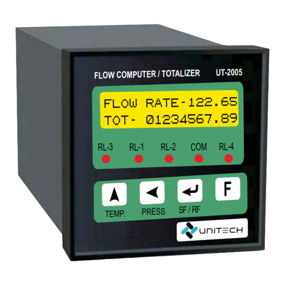
Model No. : UT-2005
LEVEL MONITORING SYSTEM [VERTICAL]
WITH GSM COMMUNICATION
Weig ht:0 00.0 0Ton
000. 0 PSI 30.0 *C
CO M.
R2
R1
RL-1
RL-2
COM.
M
Available size : 96x96-LCD,96x96-LED,96x48
External Box : Ex. Flameproof / M S or S S Box
External Box : Ex. Flameproof / MS Or Ip65 Box
@
www.utplindia.in
sales@utplindia.in
+91 7046223333 , 9427301436
www
Advertisement
Table of Contents

Related Manuals for Unitech UT-2005


Summary of Contents for Unitech UT-2005
- Page 1 INSTRUCTION MANUAL Model No. : UT-2005 LEVEL MONITORING SYSTEM [VERTICAL] WITH GSM COMMUNICATION Weig ht:0 00.0 0Ton 000. 0 PSI 30.0 *C CO M. RL-1 RL-2 COM. Available size : 96x96-LCD,96x96-LED,96x48 External Box : Ex. Flameproof / M S or S S Box External Box : Ex.
- Page 2 LEVEL MONITORING SYSTEM UT-2005 PRE CAUTIONS, WARNING AND DISPOSAL ACTION WARNING Electrical Consideration / Precautions The controller is considered “Rack and panel mounted equipment” per EN 61010-1, Safety Requirements for electrical equipment for Measurement, Control and Laboratory Use, Part 1: General Requirements. Conformity with 2/23/EEC Low Voltage Directive, requires the user to provide adequate protection against a shock hazard.
-
Page 3: Table Of Contents
LEVEL MONITORING SYSTEM UT-2005 CONTENTS OVERVIEW ....................INTRODUCTION ..................NSTALLATION ........................................MOUNTING ....................EXTERNAL DIMENSION TECHNICAL SPECIFICATIONS ........................................WIRING DIAGRAM PROGRAMMING ..................................OPERATION INTERFACE ..............MODE ACCESS FLOW CHART OPERATIONAL MODES ....................................SETUP MODE ................. -
Page 4: Overview
Introduction Function Steam Flow Computer UT-2005 are designed to measure the Flow of Superheated Steam & Saturated Steam in Mass or in terms of normalized Volume. This Flow Meter Computes Compensated Steam Flow by receiving input From Vortex Flow Meter, From Volumetric Flow, Orifice Plate, ISO 5167 Computation,Venturi & Verabar Computations. -
Page 5: Technical Specifications
LEVEL MONITORING SYSTEM UT-2005 Technical Specifications TECHNICAL SPECIFICATIONS : 0~20mA dc, 4~20mA DC DP TRANSMITTER PT TRANSMITTER : 0~20mA dc, 4~20mA DC Type Of Input TEMPERATURE : RTD Pt-100 Accuracy + 0.25% of Full Scale Input Range Limits 0.1 to 99999 Programmable, with decimal point selection Input Impedance >330 K for Voltage &... -
Page 6: Wiring Diagram
LEVEL MONITORING SYSTEM UT-2005 Wiring Diagram 1 2 3 4 5 6 7 24VDC CAUTION TEMP.(RTD PT-100) TANK LEVEL WIRING CONSIDERATION Shielded twisted pair wire is used for all analog I/P, Process sensors RTD, Thermo-couple, mV-mA DC, Volt DC, Linear input and Communication. -
Page 7: Programming
LEVEL MONITORING SYSTEM UT-2005 PROGRAMMING Operation Interface FRONT VIEW LEVEL INDICATOR UT-2005 Weight Display Weight : 020.05 Ton Temperature Pressure Display 426.7PSI 30.0 C Display Relay-2 LED Relay-3 LED Relay-4 LED Relay-1 LED COM LED PASS Key MODE Key UP Key ENTER Key www.utplindia.in... -
Page 8: Mode Access Flow Chart
LEVEL MONITORING SYSTEM UT-2005 Mode Access Flow Chart. Mode Selection Normal Mode Press key to enter into Flow:1234.5 m3/Hr the Programming mode from Tot.:1234567890.1 Normal mode Change Calibration Configuration Mode Password Mode Mode Setup Mode Calibration Mode Change Password Mode Select... -
Page 9: Operational Modes
LEVEL MONITORING SYSTEM UT-2005 OPERATIONAL MODES Seup Mode ‘Setup Mode’ will shown by pressing key in the Normal Mode. Display Range Parameter Default Value PASSWORD FOR PARAMETER SETTING Values between Password : 0000 Scroll the digit by key, increase by key. -
Page 10: Calibration Mode
LEVEL MONITORING SYSTEM UT-2005 Calibration Mode ‘Calibration Mode’ Mode will shown by pressing key, after Configuration Mode display. Display Range Parameter Default Value PASSWORD FOR PARAMETER SETTING Values between Password : 0000 Password for Calibration Mode Parameters 0000 Enter Password... -
Page 11: Change Password Mode
LEVEL MONITORING SYSTEM UT-2005 Change Password Mode ‘Change Password Mode’ Mode will shown by pressing key, after Calibration Mode display. Display Range Parameter Default Value PASSWORD FOR PARAMETER SETTING Password : 0000 Values between Password for Calibration Mode Parameters 0000... -
Page 12: Error Message
LEVEL MONITORING SYSTEM UT-2005 Error Message. In case the following error messages appear in the display of controller, please refer to the Error message table below, or call technical support. Sign Description Solution Open the Input Connection Check the Input sensor wiring... -
Page 13: Communication [Modbus Rtu] Protocol
GSM NETWORK GSM TOWER MOBILE PHONE GSM MODULE Indicator www.utplindia.in UNITECH TECHNOCRATS PVT LTD All content are subject to change without notice FACTORY:- 78/1/Z/3-Makarpura G I D C .., due to continuous improvements. +91 7046223333 , 9427301436 N/R Vadasar Bridge.
Need help?
Do you have a question about the UT-2005 and is the answer not in the manual?
Questions and answers