
Related Manuals for Unitech UT-1405


Summary of Contents for Unitech UT-1405
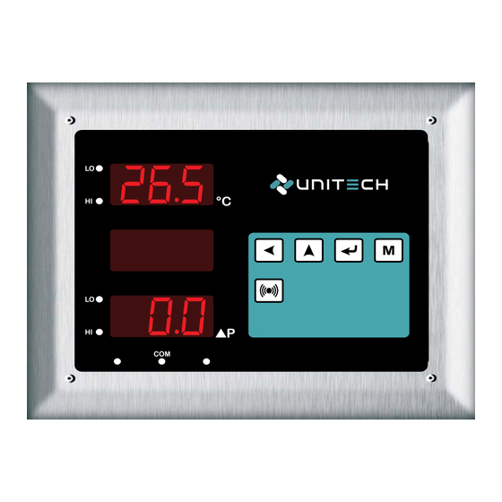
- Page 1 INSTRUCTION MANUAL Model No. : UT-1405 CLEAN ROOM INDICATOR (TEMP. & ROOM PRESSURE P Δ INDICATOR) 26.5 www.utplindia.in sales@utplindia.in +91 7046223333 , 9427301436...
- Page 2 12 / 24 VDC – a switch, fuse (1A, 125A) or a circuit breaker. The above items should be installed together with UT-1405 for the products electrical protection. The switch, Fuse or circuit-breaker should be located close to the controller, within easy reach operator.
-
Page 3: Table Of Contents
CLEAN ROOM INDICATOR [T+DP] UT-1405 CONTENTS OVERVIEW ....................INTRODUCTION ..................NSTALLATION ........................................MOUNTING ....................EXTERNAL DIMENSION ....................TECHNICAL SPECIFICATIONS ....................WIRING DIAGRAM PROGRAMMING ..................................OPERATION INTERFACE ..............MODE ACCESS FLOW CHART OPERATIONAL MODES ................................CONFIGURATION MODE .................... -
Page 4: Overview
1. OVERVIEW Introduction Function The UNITECH “CLEAN ROOM INDICATOR [T+DP] : UT-1405" is specially designed to display Temperature, Humidity a Room Pressure Difference in one unit. The instrument accept inputs from standard T + RH sensor or internal sensor. The instrument display the temperature ( C) in the range of 0 to 100 C and Humidity in the range of 0.0 to 100.0%... -
Page 5: Technical Specifications
CLEAN ROOM INDICATOR [T+DP] UT-1405 Technical Specifications TECHNICAL SPECIFICATIONS Nos Of Input 3 Nos (Temp. + RH + DP) Temperatures Input Integral Or Remote (external) Input Integral Or Remote (external) Humidity Input DP Input Integral Or Remote (external) 24V/5V DC @ 30mA max, Isolated from Input & Output Transmitter Power Supply 0.25 % on FS... - Page 6 CLEAN ROOM INDICATOR [T+DP] UT-1405 Technical Features FEATURES FDA 21 CFR Part 11 - GAMP - 4 compatible Microcontroller based indicator wit hinbuilt Temperature & DP measurement in single enclosure. Incorporates highly stable built-in or DP sensor. (with different unit like mmWc / pa / kpa / mmhg).
-
Page 7: Wiring Diagram
CLEAN ROOM INDICATOR [T+DP] UT-1405 Wiring Diagram CAUTION WIRING CONSIDERATION Shielded twisted pair wire is used for all analog I/P, Process sensors RTD, Thermo-couple, mV-mA DC, Volt DC, Linear input and Communication. SENSOR RS-485 24VDC AILURE TO COMPLY WITH THESE INSTRUCTION MAY RESULT... -
Page 8: Programming
CLEAN ROOM INDICATOR [T+DP] UT-1405 PROGRAMMING ºC High High FRONT VIEW NORMAL VIEWS 1. 7 segment Display 4 Digit 7 segment dedicated to display the present value. In Programing mode it shows Parameter and its value. 2 LOW When LED is On It indicates the status of Low Value. -
Page 9: Mode Access Flow Chart
CLEAN ROOM INDICATOR [T+DP] UT-1405 Mode Access Flow Chart. Normal Mode [PV] 8888 Configuration Change Setup Calibration Mode Password Mode Mode Mode MODE Press Press Press Press Mode Selection Press key to enter into the Programming mode from Normal mode... -
Page 10: Operational Modes
CLEAN ROOM INDICATOR [T+DP] UT-1405 OPERATIONAL MODES Configuration Mode Mode ‘Configuration Mode’ will shown by pressing key, will be display and then by pressing Range / Values Display Parameter CONFIGURATION MODE Range : Values between Password for Config. Mode Parameters... - Page 11 CLEAN ROOM INDICATOR [T+DP] UT-1405 Continue Configuration Mode Range / Values Display Parameter Pressure Offset Factory Set Value 00 to 62 Value s between Note : Factory Set Value Default Value : 15 Change value by key, or by key.
-
Page 12: Setup Mode
CLEAN ROOM INDICATOR [T+DP] UT-1405 Setup Mode Conf ‘Setup Mode’ Mode will shown by pressing key, after Mode display. Range / Values Display Parameter 0000 9999 SETUP MODE Range : Values between Password for Setup Mode Parameters Default Value : 0000... -
Page 13: Calibration Mode
CLEAN ROOM INDICATOR [T+DP] UT-1405 Pressure Range 00 0 99 9 Range : Values between Change to Pressure Range Scroll the digit by key, Increase by key. Default Value : 1 . 0 0 Calibration Mode Setp ‘Calibration Mode’ Mode will shown by pressing key, after Mode display. -
Page 14: Change Password Mode
CLEAN ROOM INDICATOR [T+DP] UT-1405 Change Password Mode ‘Change Password Mode’ Mode will shown by pressing key, after Mode display. Range / Values Display Parameter CPAS 0000 9999 CHANGE PASSWORD MODE Range : Values between Password for Change Password Mode. -
Page 15: Communication [Modbus Rtu] Protocol
40010 READ / WRITE TEMP. ALARM SE T POINT- www.utplindia.in UNITECH TECHNOCRATS PVT LTD All content are subject to change without notice FACTORY:- 78/1/Z/3-Makarpura G I D C .., due to continuous improvements. +91 7046223333 , 9427301436 N/R Vadasar Bridge. -
Page 16: Modbus System Schematic
DATA+ RS-485 BUS Ethernet DATA- CONVERTER www.utplindia.in UNITECH TECHNOCRATS PVT LTD All content are subject to change without notice FACTORY:- 78/1/Z/3-Makarpura G I D C .., due to continuous improvements. +91 7046223333 , 9427301436 N/R Vadasar Bridge. /p-Gayatri emple Doc.
Need help?
Do you have a question about the UT-1405 and is the answer not in the manual?
Questions and answers