
Related Manuals for Unitech UT-1405


Summary of Contents for Unitech UT-1405
- Page 1 INSTRUCTION MANUAL Model No. : UT-1405 TEMP. AND DIFF. PRESS. INDICATOR [CLEAN ROOM INDICATOR] 888.8 5. 0 8888 UT-1405 UT-1405 www.utplindia.in sales@utplindia.in +91 7046223333 , 9427301436...
- Page 2 12 / 24 VDC – a switch, fuse (1A, 125A) or a circuit breaker. The above items should be installed together with UT-1405 for the products electrical protection. The switch, Fuse or circuit-breaker should be located close to the controller, within easy reach operator.
-
Page 3: Table Of Contents
TEMP. AND DIFF. PRESS. INDICATOR UT-1405 CONTENTS OVERVIEW ....................INTRODUCTION ..................NSTALLATION ....................EXTERNAL DIMENSION ......................................... MOUNTING ....................TECHNICAL SPECIFICATIONS ..................TECHNICAL FEATURES ....................WIRING DIAGRAM PROGRAMMING ..................................OPERATION INTERFACE ..............MODE ACCESS FLOW CHART OPERATIONAL MODES ................... -
Page 4: Overview
There are 4 keys provided for easy configuration and setup. Mount Anywhere The UT-1405 product group is Clean Room instruments that must be Flush or Wall mounted. The wiring terminals must be provided. the UT-1405 is environmentally hardened and, if suitably handled, can be mounted virtually anywhere in clean room or enclosure wall mounted or Flameproof enclosure or even on the AHU or Technical Area. -
Page 5: Mounting
TEMP. AND DIFF. PRESS. INDICATOR UT-1405 Mounting 1. Cutout required in the back wall or partition : 125[H] X 100[W] 2. Mount the frame in the Surface cutout. 3. Fix the frame on surface by screws. 4. Insert the Power & Communication Cables. -
Page 6: Technical Specifications
TEMP. AND DIFF. PRESS. INDICATOR UT-1405 Technical Specifications TECHNICAL SPECIFICATIONS 2 Nos. Temperature and DIFF. PRESS. No. of Input Input Integral Remote [External] Temp + DP Input Ch-1 [Temperature] : 4 Digit Seven segment 0.56” Red display Display [PV] Ch-2 [DIFF. PRESS.] 4 Digit Seven segment 0.56”... -
Page 7: Technical Features
TEMP. AND DIFF. PRESS. INDICATOR UT-1405 Technical Features Ø FDA 21 CFR part 11 - GAMP-4 compatible. Ø Micro controller-based indicator with inbuilt DP measurement. Ø Incorporates highly stable built-in sensor. Ø 3 Digit, 0.56" Bright LED display for displaying parameter. -
Page 8: Programming
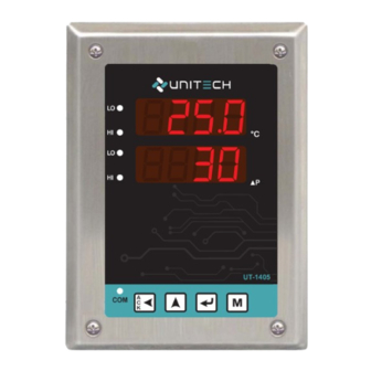
TEMP. AND DIFF. PRESS. INDICATOR UT-1405 PROGRAMMING Operation Interface 888.8 Display-1 TEMP. CH-1 Low Alarm LED CH-1 High Alarm LED 888.8 5. 0 Display-2 DP CH-2 Low Alarm LED CH-2 High Alarm LED www.utplindia.in UT-1405 COM LED MODE Key PASS Key... -
Page 9: Mode Access Flow Chart
TEMP. AND DIFF. PRESS. INDICATOR UT-1405 Mode Access Flow Chart. Setup Configuration Change Calibration Buzzer Mode Mode Mode Password Mode Mode Normal Mode 8888 MODE MODE MODE MODE MODE COnf SETP PASC BUZZ 8888 Mode Selection pass pass pass pass... -
Page 10: Operational Modes
TEMP. AND DIFF. PRESS. INDICATOR UT-1405 OPERATIONAL MODES Configuration Mode ‘Configuration Mode’ will shown by pressing key in the Normal Mode. PASS : CONFIGURATION MODE PASSWORD Conf Password for Mode Parameters Scroll the digit by key, Increase by key. Default Password for access Config. mode : 1357... - Page 11 TEMP. AND DIFF. PRESS. INDICATOR UT-1405 aLST : ALARM STATUS ENABLE/DISABLE Enable OR Disable Alarm of particular Input. Press key to access sub parameters, the sub parameters are : 1sp1 : Input 1 [TEMP.] Alarm 1. Values are : - Enable,...
- Page 12 TEMP. AND DIFF. PRESS. INDICATOR UT-1405 COMM : COMMUNICATION PARAMETER Device Active Master-Slave Communication configuration parameter. Press key to access sub parameters, the sub parameters are : NoDE : Node Address. Device Address for Communication 0000 9999 Values are between baud : Baud Rate.
- Page 13 TEMP. AND DIFF. PRESS. INDICATOR UT-1405 hour III. : Hours[24Hr.]. Real time Hours. 0000 0024 Values are between : Day / Date. Present Calender Date. 0000 0031 Values are between : Month. Present Month. 0000 0024 Values are between year : Year.
-
Page 14: Setup Mode
TEMP. AND DIFF. PRESS. INDICATOR UT-1405 Setup Mode Conf ‘Setup Mode’ Mode will shown by pressing key, after Mode display. PASS : SETUP MODE PASSWORD SETP Password for Mode Parameters Scroll the digit by key, Increase by key. Default Password for access Setup mode : 1111 ASSIGN SET POINTS FOR EACH INPUT ALARMS Set the alarm Set Point for Audio [Buzzer] front LED. -
Page 15: Calibration Mode
TEMP. AND DIFF. PRESS. INDICATOR UT-1405 Calibration Mode SETP ‘Calibration Mode’ Mode will shown by pressing key, after Mode display. PASS : CALIBRATION MODE PASSWORD Password for Mode Parameters Scroll the digit by key, Increase by key. Default Password for access Setup mode : 1234 CAL1 : CALIBRATION OF INPUT. -
Page 16: Change Password Mode
TEMP. AND DIFF. PRESS. INDICATOR UT-1405 Change Password Mode ‘Change Password Mode’ Mode will shown by pressing key, after Mode display. PASS : CHANGE PASSWORD MODE PASSWORD pAsC Password for Mode Parameters Scroll the digit by key, Increase by key. -
Page 17: Communication [Modbus Rtu] Protocol
WRITE ONLY NOTE : Sr. no. 22 is applicable if AHU Status digital signal is available. MODBUS system schematic. The system schematic for RS-485 Modbus protocol are as follows : UT-1405 Device-1 UT-1405 Device-2 UT-1405 Device-3 UT-1405 Device-256 Upto 256...
Need help?
Do you have a question about the UT-1405 and is the answer not in the manual?
Questions and answers