Table of Contents
Advertisement
Quick Links
Advertisement
Table of Contents

Related Manuals for Growatt ShineMaster-X


Summary of Contents for Growatt ShineMaster-X
- Page 1 ShineMaster-X User Manual...
- Page 2 Notice All products, services and features are stipulated by the contract made between Growatt and the customer. All or part of the products, services and features described in this document may not fall under the scope of purchase or usage.
-
Page 3: Table Of Contents
Connect the DO signal cable ................9 Install the SIM card and the 4G antenna ............10 6 Power on the system..............11 7 ShineMaster-X built-in page operations ........ 12 Login ........................12 7.1.1 Option 1: Access the built-in page with connection to the computer using an Ethernet cable.............. - Page 4 Add, delete or query devices for monitoring via ShineMaster-X ....27 7.4.1 Add or delete a device ..................27 7.4.2 Delete a device ....................38 7.4.3 Check the device running information ............39 7.5 ShineMaster-X server communication configuration ........40 7.5.1 ShineMaster-X network configuration ............
-
Page 5: About This Manual
Dear users, thank you for choosing the ShineMaster-X datalogger developed and manufactured by Shenzhen Growatt New Energy Co., Ltd (hereinafter referred to as Growatt). We sincerely hope that this product can serve your needs. Meanwhile, your feedback on the product's performance and functionality would be most welcomed and appreciated. -
Page 6: Product Introduction 2
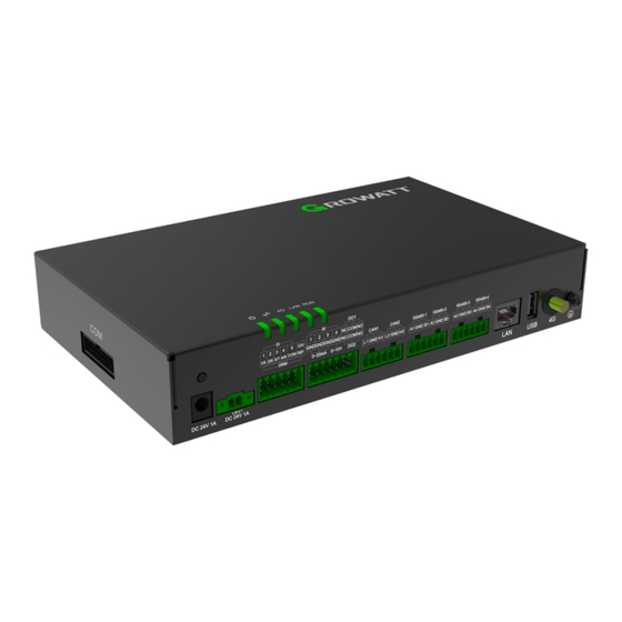
Product introduction 2 Before installing the equipment, please read through the User Manual to get Ÿ familiar with product information and safety precautions. Ÿ Insulated tools must be used when installing the equipment. For personal safety, please wear personal protective equipment. Description Description LED indicators (POWER, BLE, 4G,... -
Page 7: Installation Requirements
3 Installation requirements Dimensions: 39.4mm 244.6mm 230.5mm 49.4mm 264.6mm Clearance: ≥100mm ≥200mm ≥200mm ≥300mm... -
Page 8: Install The Equipment 4
Note: Install the device on a flat and solid wall surface indoors. Ø When mounting the ShineMaster-X on a wall, make sure the cable connection Ø area is facing downwards to facilitate cable connection and maintenance. It is recommended to use the self-tapping screws and expansion screws Ø... -
Page 9: Electrical Connections
5 Electrical connections 5.1 Prepare the cables Cable type Recommended specifications Cross-section area: 4mm~6mm or 12AWG~10AWG PE cable outdoor copper cable Rs485communication Cross-section area: 0.2mm~2.5mm or 24AWG~14AWG cable dual-/multi-core cable MBUS cable (optional) Delivered with the package DI signal cable Output power cable Cross-section area: 0.2mm~1.5mm or 24AWG~16AWG dual-/multi-core cable... -
Page 10: Connect The Rs485 Communication Cable
The ShineMaster-X can be connected to RS485 communication devices, such as the inverter, the environmental monitor and the meter via the RS485 port. Please make sure that RS485+ is connected to RS485A of the ShineMaster-X, and Ø RS485- to the RS485B port of the ShineMaster-X. -
Page 11: Connect The Di Signal Cable
Inverter Inverter 5.4 Connect the DI signal cable Note: The ShineMaster-X can receive DI signals such as remote grid dispatching Ø commands and alarms over DI ports. It can only receive passive dry contact signals. It is recommended that the signal transmission distance be less than or equal Ø... -
Page 12: Connect The Output Power Cable
Note: Ø The ShineMaster-X can drive the coil of the intermediate relay via the 12V power output port in export limitation or audible-visual alarm scenario. It is recommended that the transmission distance be less than or equal to 10 m. -
Page 13: Connect The Do Signal Cable
Port Description Supports input current of 4mA~20mA and 0mA~20mA Supports input voltage of 0V~10V 5.7 Connect the AI signal cable Note: The DO port supports up to 12V signal voltage. Ø It is recommended that the transmission distance be less than or equal Ø... -
Page 14: Install The Sim Card And The 4G Antenna
5.8 Install the SIM card and the 4G antenna Note: Please prepare a standard SIM card (dimensions: 15mm*25mm). Determine the Ø SIM card installation direction according to the silk screen. Press the SIM card in place to lock it. In this case, the SIM card is correctly Ø... -
Page 15: Power On The System
The rated input voltage of the power adaptor is 100V AC~240V AC, and the rated input frequency is 50Hz/60Hz. Please select an AC socket that matches the power adapter. Ø 2. Observe the LED indicators to check the ShineMaster-X operating status LED indicator Meaning Off: power supply is abnormal;... -
Page 16: Shinemaster-X Built-In
7.1 Login Note: The DHCP of ShineMaster-X is disabled by default before delivery, and the Ø default IP address is: 192.168.0.254. Upon first use, please connect ShineMaster- X to the computer using an Ethernet cable to access the built-in page. -
Page 17: Option 2: Access The Built-In Page Via The Router
Fig 7-4 Built-in page 7.1.2 Option 2: Access the built-in page via the router Note: The DHCP of ShineMaster-X is disabled by default before delivery. To access the Ø built-in page via the router, you need to enable DHCP of ShineMaster-X first. - Page 18 Fig 7-6 DHCP setting Verify if the ShineMaster-X has enabled DHCP function, then connect the PC and Ø ShineMaster-X to the same router, ensuring that they are in the same network segment. Ø Check the network segment the server is in.
- Page 19 Fig 7-8 IP query command Fig 7-9 IP query field Ø As we can see that the IP address assigned to the computer by the router is 192.168.10.220, so that the network segment of the router is 192.168.10.X. You can input 192.168.10.254 on the browser to access the built-in page. Fig 7-10 Login IP address Fig 7-11Login page...
-
Page 20: Computer Ip Address Settings
Enter the username (admin) and password (admin) to sign in, and you can Ø access the built-in page upon successful login. Fig 7-12 Successful login Fig 7-13 Built-in page 7.1.3 Computer IP address settings (1) Click the Start button in the lower-left corner > Control Panel > Network and Sharing Center. - Page 21 (2) Click Change Adapter Settings on the left pane. Fig 7-15 Change Adapter Setting (3) Find the “Local Connection” icon. Double-click or right-click the Local Area Connection, and select “Property”. Fig 7-16 Local Area Connection (4) Select Internet Protocol Version 4 (TCP/IPv4) > Property. Fig 7-17 Ethernet properties...
- Page 22 (5) In the Internet Protocol Version 4 (TCP/IPv4) window, select “Use the following IP address”, then input the IP address 192.168.0.XXX (XXX ranges from 2 to 253), the Subnet Mask: 255.255.255.0 and the Default Gateway: 192.168.0.1. It is not required to set the DNS Server. Fig 7-18 Change the IP address (6) After the configuration is complete, click “Save”.
-
Page 23: Built-In
7.2 Built-in page introduction 7.2.1 Layout Fig 7-19 Built-in page layout Main menu Sub menu Selected menu item Information & Operation area Language Account & Log out The Main Menu is on the top of the page labeled with A, including “System Information”, “Product Maintenance”, “System Settings”... -
Page 24: Shinemaster-X System Information
Under the System Information menu, you can view Product Information, Device List, and Communication Information, etc. Fig 20 Product Information Product Information Serial Number of ShineMaster-X, software version, etc. Information about added devices and online/offline Device List status Detailed information about wired network and wireless... -
Page 25: Shinemaster-X System Settings
7.2.4 ShineMaster-X system settings Fig 22 System Settings Parameter settings regarding ShineMaster-X Wired Communication connected to the server via the Ethernet port Parameter settings regarding ShineMaster-X Wireless Communication connected to the server via the network interface card (NIC) Parameter settings regarding RS485-1, RS485-2,... -
Page 26: Shinemaster-X Device Monitoring
Device Maintenance monitor and PID device 7.3 ShineMaster-X communication configuration 7.3.1 ShineMaster-X RS485 communication configuration Note: The baud rate of the four routes RS485-1, RS485-2, RS485-3, RS485-4 is set to 9600 by default before delivery. You can set the baud rate respectively based on the installation environment. - Page 27 (2) Select the target RS485 route from the dropdown list of “Port”. Four options are available: RS485-1, RS485-2, RS485-3 and RS485-4. Fig 25 Set the RS485 route (3) Select the Baud Rate from the dropdown list. The value can be set to “4800”, “9600”, “19200”, “38400”...
- Page 28 (6) Select the Data Bit from the dropdown list. The value can be set to "6", "7" or "8". Fig 29 Set the RS485 data bit (7) Select the target Modbus Protocol from the dropdown list of “Protocol Type”. Fig 30 Set the protocol type (8) Select “Master/Slave”...
-
Page 29: Shinemaster-X Can Communication Configuration
“System Information” menu. Fig 33 RS485 configuration 7.3.2 ShineMaster-X CAN communication configuration (1) Sign in the built-in page referring to Section 7.1 with the username (admin) and password (admin). Select “CAN” from the left pane under the “System Settings”... - Page 30 (3) Select the Baud Rate from the dropdown list. The value can be set to “125K”, “250K”, or “500K”. Fig 36 Set the CAN baud rate (4) Select the target Modbus Protocol from the dropdown list of “Protocol Type”. Fig 37 Set the CAN protocol type (5) After the configuration is complete, select “Submit”.
-
Page 31: Add, Delete Or Query Devices For Monitoring Via Shinemaster-X
7.4 Add, delete or query devices for monitoring via ShineMaster-X You need to add the devices on the “ShineMaster-X Ø datalogger settings” page in order to monitor the PV devices with the ShineMaster-X. The ShineMaster-X built-in page will display data related Ø... - Page 32 (2) Click “Add”, then the “Add data” window will pop up. Fig 41 Add the inverter (3) Select the RS485 route from the “Port” dropdown list, including RS485-1, RS485-2, RS485-3 and RS485-4. Fig 42 Select the RS485 route (4) Select “Inverter” from the “Type” dropdown list. Fig 43 Select the device type...
- Page 33 (5) Input the device's initial address into the “Start address” filed. For instance: if the address of the PV inverter that should be monitored is “1”, please set this value to “1”. Note: Up to devices can be added to each RS485 route and the address of the PV device ranges from 1 to 254.
- Page 34 Fig 47 Check the device list 2. Add the meter (1) Sign in the built-in page referring to Section 7.1 with the username (admin) and password (admin). Select “Device Monitoring” from the first-level menu > “Meter” from the second-level menu > “Equipment Maintenance” from the third-level menu.
- Page 35 (3) Select the RS485 route from the “Port” dropdown list, including RS485-1, RS485-2, RS485-3 and RS485-4. Fig 50 Select the RS485 route (4) Select the meter type from the “Type” dropdown list, including “Eastron single-phase meter”, “Eastron three-phase meter”, “CHINT single-phase meter”, “CHINT three-phase meter”, “ARREL meter”...
- Page 36 (6) Number of addresses: ShineMaster supports adding multiple devices of the same type with consecutive addresses at one time. For example, for the four meters to be monitored with the addresses 1, 2, 3 and 4, set "Start Address" to "1", and "Number of Addresses"...
- Page 37 3. Add the environmental monitor (1) Sign in the built-in page referring to Section 7.1 with the username (admin) and password (admin). Select “Device Monitoring” from the first-level menu > “Environmental monitor” from the second-level menu > “Equipment Maintenance” from the third-level menu. Fig 56 Device Maintenance page of Environmental Monitor (2) Click “Add”, then the “Add data”...
- Page 38 (4) Select the type of the environmental monitor from the “Type” dropdown list. Fig 59 Select the environmental monitor type (5) Input the device's initial address into the “Start address” filed. For instance: if the address of the environmental monitor that should be monitored is “1”, please set this value to “1”.
- Page 39 (7) Upon submission, the “Setting succeeded” message will be displayed. Then verify if the environmental monitor has been successfully added by choosing “System Information” from the first-level menu > “Device List” from the second- level menu. Fig 62 Setting succeeded Fig 63 Device list 4.
- Page 40 (2) Click “Add”, then the “Add data” window will pop up. Fig 65 Add the PID device (3) Select the RS485 route from the “Route” dropdown list, including RS485-1, RS485-2, RS485-3 and RS485-4. Fig 66 Select the RS485 route (4) Select the type of the PID device from the “Type” dropdown list. Fig 67 Select the PID device type...
- Page 41 (5) Input the device's initial address into the “Start address” filed. For instance: if the address of the PID device that should be monitored is “1”, please set this value to “1”. Note: Up to devices can be added to each RS485 route and the address of the PV device should be within the range of 1- (6) Number of addresses: ShineMaster supports adding multiple devices of the same type with consecutive addresses at one time.
-
Page 42: Delete A Device
7.4.2 Delete a device You can delete the device, including the inverter, meter, environmental monitor and PID device. To take the inverter as an example: (1) Sign in the built-in page referring to Section 7.1 with the username (admin) and password (admin). Select “Device Monitoring” from the first-level menu > “Inverter”... -
Page 43: Check The Device Running Information
7.4.3 Check the device running information Note: Ø The ShineMaster-X built-in page will display data related to the devices, including the Inverter, Meter, Environmental Monitor and PID device. You can also view the historical data. The following illustrates the procedure to check device running information, taking the inverter as an example. -
Page 44: Shinemaster-X Server Communication Configuration
7.5 ShineMaster-X server communication configuration 7.5.1 ShineMaster-X network configuration Note: The DHCP of ShineMaster-X is disabled by default before delivery. If you select Ø network connection via the router, you need to enable DHCP. Ø ShineMaster-X supports connection to the server over wired network or the 4G network. - Page 45 (3) Upon successful configuration, you need to restart the device for the change to take effect. 3. Parameter settings for using ShineMaster-X with a fixed IP address (1) Sign in the built-in page referring to Section 7.1.1 with the username (admin) and password (admin), then select Wired Communication on the left pane under the System Settings menu to disable the DHCP function.
-
Page 46: Shinemaster-X Server Address Settings
(1) Sign in the built-in page referring to Section 7.1 with the username (admin) and password (admin), then select Server on the left pane under the System Settings menu. Select “Enable”, then input the server port number, domain name, e.g. server-cn.growatt.com/server.growatt.com, and the data upload interval. Fig 85 Server configuration (2) Click “Submit”. -
Page 47: Power Adjustment Settings
7.6 Power adjustment settings 7.6.1 Enable active power adjustment Note: The Export Limitation function is enabled by default. If it is disabled, it will not be able to adjust the power of the PV inverter or the storage inverter, and can only monitor the data. -
Page 48: Meter Configuration
100ms. 2. Meter CT: Select the CT configuration of corresponding specifications based on on-site situations (the CT ratio can be customized). If the ShineMaster-X is integrated in the SEM-X, the CT has been configured before delivery, therefore configuration of the CT is not required and the default value is “No”. -
Page 49: Adjustment Management
7.6.3 Adjustment management This setting item is to set the power adjustment mode: Ø Total Phase Adjustment: read Phase A, B and C power of the meter or the total power. Adjust the power of the PV inverter or storage inverter based on the total- phase power and direction. - Page 50 Grid First: prioritizes supplying power to the loads. Both PV power and battery Ø power can be used for supporting the loads. The surplus power will be fed to the grid, which should not exceed the pre-set feed-in power. Ø PV-only storage: prioritizes supplying power to the loads and the battery is not allowed to discharge.
- Page 51 Multiple time mode settings. You can select Special Day 1, Special Day 2, Quarter (1, 2, 3, 4) or Full year, as shown below: Procedure to set the working mode for idle time is illustrate below: (1) Add a time segment. When the cursor is on the Start Time (00:00) filed, the “x” icon will be displayed, as the following figure shows.
-
Page 52: Third-Party Server Configuration
Disable: Disable connection over MODBUS TCP, prohibiting the third-party management system from connecting to the ShineMaster-X Enable (limited): Only the pre-configured client IP addresses are allowed to be connected to the ShineMaster-X server. Less than 3 client IP addresses can be connected and they are configurable. -
Page 53: Third-Party Server Configuration Over Iec104
ShineMaster-X server. Enable (limited): Only the pre-configured client IP addresses are allowed to connect to the ShineMaster-X server. Less than 3 client IP addresses can be connected and they are configurable. 7.8 Power plant relationship configuration Note: All meters involved in the power plant relationship should be on the same node. -
Page 55: Technical Specifications
8 Technical specifications General Dimensions (W/H/D) 140.0 mm*232.0 mm*40.0 mm Weight 1.32 kg(+-0.5kg) IP rating IP20 Operating environment Operating temperature -30°C ~ 60°C (-22°F ~ 149°F) Storage temperature -40°C ~ 70°C (-40°F ~ 158°F) Installation location Indoors Communication method Max. communication distance: 500 m, up to 48 units can RS485 be connected CAN bus... -
Page 56: Contact Us 9
Contact us 9 If you have technical problems concerning our products, you can contact the local Growatt office or Growatt Support. Shenzhen Growatt New Energy Co., Ltd. 4-13/F, Building A, Sino-German (Europe) Industrial Park, Hangcheng Blvd, Bao’an District, Shenzhen, China +86 755 2747 1942 service@ginverter.com... - Page 57 Download Manual Shenzhen Growatt New Energy Co., Ltd. 4-13/F, Building A, Sino-German (Europe) Industrial Park, Hangcheng Blvd, Bao’an District, Shenzhen, China +86 755 2747 1942 service@ginverter.com en.growatt.com GR-UM-409-A-00 (PN: 044.0102800)
Need help?
Do you have a question about the ShineMaster-X and is the answer not in the manual?
Questions and answers