Advertisement
Quick Links
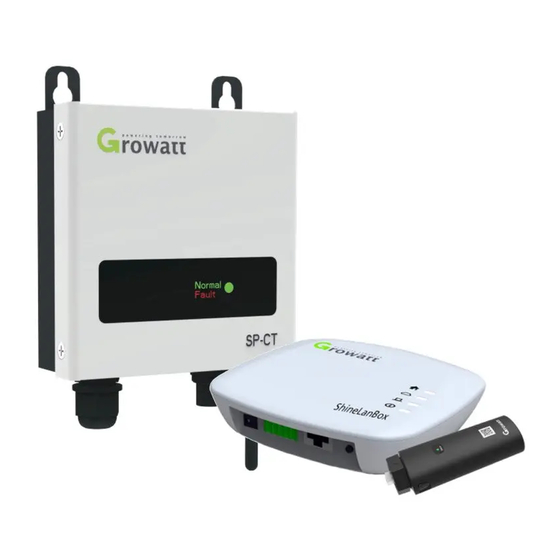
Growatt ShineLimit
User manual
For more info, please download from http://server.growatt.com
+86 755 2951 5888
+86 755 2747 2131
service@ginverter.com
www.ginverter.com
Unpacking
Step1.
1.1 Unpacking ShineLink, and check the package
device list:
1.3 SP-CT SE
Working normal
Green indicator solid on
In pair status
Green indicator flash
Fault e.g L and N connected
Red indicator solid on
reversely or GND wire unconnected
1.3.1 Nameplate description
There is some essential information such as product model,
specifications and approva
l on the Nameplate in the
rear of SP-CT:
2.2 Install SP-CT
2.2.1 Basic requirements of mounting
A
Mount on solid surface and can accommodate weight of SP-CT long
time. ( refer to the chapter 3.3 to know the precise weight)
B Mount on where has enough space for SP-CT ( refer to the chapter 3.3).
C Do not mount on flammable construction materials .
D Designed with IP65 degree for indoor or outdoor applications .
E Ambient humidity range: 0~95%.
F Ambient temperature range: -25
60
.
℃~
℃
G Vertically installation or tilt angle 15-dgress installation is ok, as the
chart 5.1 .
·Safety precaution
1) Before using the unit, please read this manual carefully.
Otherwise, if you don't follow the steps described of the
instruction to use and cause any damaged,Growatt has the
right not to service you.
2) All the tasks described in this manual should be performed by
qualified personnel.
3) During installation, please don't touch any inside part of this
unit besides terminals.
4) All wires connection of unit should be abided by the local
electric safety criterions.
5) If necessary, please contact specified installer
·Product Description
Growatt ShineLimit0 is the zero output control system for
pv plant. It use RF wireless devices to communicate, like
ShineRFStick and SP-CT, control the pv inverter active power
by the power of loads to enable zero output to Grid, and can be
monitored from the net server by RJ45. The System Diagram
as bellow:
Item
A
ShineLanBox
B
ShineRFStick
C
D
Power adapter
E
Fixing screws
F
Wall plastic posts
G
1.2 Unpacking SP-CT, and check the package device
list:
Installation
Step2.
2.1 General precautions
A. Safety measures
SP-CT High voltage danger
·Qualified personnel can operate only
·The kids, the disable, non-professional are
not allowed to close.
SP-CT Ground wire connection
Ensure the SP-CT ground wire is properly
earthed
H To make sure operate and maintain available the unit, please leave
enough space for SP-CT.
I
Do not install where is near to Radio or machine which has wireless
function .
.
J Do not install the place where the children can reach.
2.3 Installation guide
2.3 Installation layout
.1
Installation layout of storage energy system with SP-CT should
be as following feature shows .
Note: The recommend distance between stored-energy machine
and SP-CT is less than 50 m.
2.3 Mounting
.2
1). Mark locations of the hole of SP-CT.
2). Insert 2 expansion screws in the holes.
3). Screw 2 screws( M5) firmly.
4). Place the SP-CT on the 2 screws .
Name
Quantity
1
1
Network
1
1
4
2
User manual
1
!
System Diagram:
Name
Item
A
PV panel
Inverter PV panel
B
Inverter
PV Inverter with ShineRFStick
C
Loads
D
SP-CT
ShineLimit detecting meter
E
Grid
F
ShineLanBox
ShineLimit controller
G
Router
Item
Quantity
Description
A
1
Growatt SP-CT
B
1
Antenna
C
1
Sensor (water-proof terminal)
D
2
M5*30 pan head screw
E
2
Expansion screw
F
1
Sucker antenna this is for SP
(Storage machine)
--
1
W
arranty card
--
1
Manual
B. Symbol used of SP-CT
Symbol
Description
Risk of electric shock!
Ground point
Alternating current
CE Mark, which means it satisfies CE criterion
RCM Mark, which means it satisfies RCM criterion.
C. Device install place please refer to the system Diagram
above.About the distance between the ShineLanBox with the
ShineRFStick and SP-CT, the maximum linear distance is
200m if there is no obstructions between then; the maximum
distance is 50m if there is one wall between then;
the maximum distance is 20m if there are two walls between
then.
2.4 Wires connection
2.4 AC auxiliary power wires connection
.1
Preparation:
(1) Ensure the grid voltage is 230VAC or 240VAC, frequency
is 50/60Hz single phase.
(2) Connection mode:
a) Type I:Connect the AC terminal of SP-CT to the AC breaker
of power distribution cabinet.
b) Type II:Press the AC terminal (British standard) of SP-CT
on the nearby socket. Because of installation outside,
the socket should be water-proof.
Caution:Ensure the utility phase of SP-CT position is same
with stored-energy machine and PV inverter phase position.
Type I
Note: Type II installation is mainly suitable for British
standard area.
Description
User loads
220V public grid
Typ II
Advertisement

Subscribe to Our Youtube Channel
Related Manuals for Growatt ShineLimit


Summary of Contents for Growatt ShineLimit
-
Page 1: Safety Precaution
1) Before using the unit, please read this manual carefully. Otherwise, if you don’t follow the steps described of the instruction to use and cause any damaged,Growatt has the right not to service you. 2) All the tasks described in this manual should be performed by Growatt ShineLimit qualified personnel. - Page 2 After power on, the Power LED on, Network LED flashing, then the ShineLanBox start to search the RF After install and power on the ShineLimit, it will start system device and connect to the server. Network LED on zero export function. If want to test the function, please...
Need help?
Do you have a question about the ShineLimit and is the answer not in the manual?
Questions and answers