
Related Manuals for Growatt ShineMaster-X


Summary of Contents for Growatt ShineMaster-X
- Page 1 ShineMaster-X Operation Manual V1.0.2.0 ShineMaster-X Operation Manual V 1.0.0.0 date: 2022-11-01...
-
Page 2: Table Of Contents
5.8 Install SIM card and 4G antenna ........................11 Power on the system ............................11 1. Connect the power .............................. 11 2. Observe the LED indicator to check the running status of ShineMaster-X ........... 12 Shinemaster-X built-in page operation ......................13 7.1 Built-in page login method ..........................13 7.1.1... - Page 3 ShineMaster-X Operation Manual V1.0.2.0 7.4 ShineMaster-X monitoring device addition, deletion and query ..............25 7.4.1 Addition and deletion of equipment ..................... 26 7.4.2 Delete device ..........................34 7.4.3 View device operation information ....................35 7.5 ShineMaster-X server communication settings ..................37 7.5.1...
-
Page 4: About This Manual
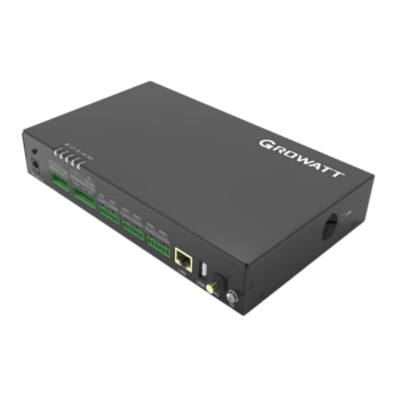
, infringement must be investigated. The version number of this manual is V1.0. Growatt has the final right to interpret this user manual. If there are changes in product parameters, appearance, packaging, etc., the latest information of the company shall prevail without prior notice. - Page 5 ShineMaster-X Operation Manual V1.0.2.0 (1) LED indicators (POWER , BLE , 4G , LAN, RUN ) (2) SIM card socket ( SIM ) (3) Install the mounting ear ( 4 ) Guide rail clips (5) COM port (6) 24 V power input port ( DC IN 24V , 1 A)
-
Page 6: Installation Requirements
Explanation Please choose a flat and firm indoor wall for installation. ⚫ When installing the ShineMaster-X on the wall, make sure that the cable connection area is facing ⚫ downwards, which is convenient for cable connection and maintenance. It is recommended to use the selftapping screws and expansion tubes provided with the box for inst ⚫... -
Page 7: Rail Installation
ShineMaster-X Operation Manual V1.0.2.0 4.1.2 rail installation Explanatio Before installation, please prepare the 35mm standard guide rail and install it firmly. ⚫ It is recommended that the effective length of the guide rail is ≥ 260mm. ⚫ 4 electrical connection Electrical connections 5.1 Cable preparation... -
Page 8: Install The Ground Wire
ShineMaster-X can be connected to RS485 communication devices such as inverters, environmental ⚫ monitors, and electric meters through the RS485 port. Please make sure that RS485+ is connected to RS485A of ShineMaster-X, and RS485- is connected ⚫ to RS485B of ShineMaster-X. -
Page 9: Cascade Connection
RS485 port of ShineMaster-X. 5.4 Install DI signal cable Explanatio ShineMaster-X can access DI signals such as remote grid dispatching commands and alarms through ⚫ the DI port, and only supports passive dry contact signal access. It is recommended that the signal transmission distance not exceed 10m. -
Page 10: Install The Power Output Line
ShineMaster-X Operation Manual V1.0.2.0 5.5 Install the power output line Explanatio In the scenario of limited power grid connection or sound and light alarm, ShineMaster-X can drive ⚫ the coil of the intermediate relay through the 12V power output port. -
Page 11: Install Ai Signal Cable
ShineMaster-X Operation Manual V1.0.2.0 5.6 Install AI signal cable Explanation ShineMaster-X can access the Al signal of the environmental monitoring sensor through the Al port. ⚫ It is recommended that the transmission distance not exceed 10m. ⚫ 1,2,3,and 4 of the Al port are connected to the Al signal +, and GND is connected to the Al signal -. -
Page 12: Install Sim Card And 4G Antenna
ShineMaster-X Operation Manual V1.0.2.0 5.8 Install SIM card and 4G antenna Explanation Please bring your own standard SIM card (maximum size: 15mm×225mm). To install the SIM card, ⚫ you can judge the installation method of the SIM card according to the silk screen on the SIM card socket. -
Page 13: Observe The Led Indicator To Check The Running Status Of Shinemaster-X
ShineMaster-X Operation Manual V1.0.2.0 2. Observe the LED indicator to check the running status of ShineMaster-X. indicator light meaning Power Indicator Always off: The power supply is working abnormally; Steady on: The power supply is working normally. bluetooth light Always off: Bluetooth is not enabled;... -
Page 14: Shinemaster-X Built-In
ShineMatser-X defaults to disable DHCP inside the factory, and the default access IP is: ⚫ 192.168.0.254, so when using ShineMaster-X for the first time, please connect ShineMaster-X to a computer through a network cable to access the built-in page. 7.1.1 Method 1: Access the built-in login page by directly connecting to the computer through a... -
Page 15: Method 2: Access The Built-In Login Page Through A Router
Figure 7- 5 Login password Figure 7- 6 DHCP settings Check to make sure that ShineMaster-X has enabled the DHCP function, and connect the PC and ⚫ ShineMaster -X to the same router so that they are in the same LAN. - Page 16 ShineMaster-X Operation Manual V1.0.2.0 Figure 7- 7 cmd command Figure 7- 8 Query IP command Figure 7- 9 Query the IP field It can be seen that the IP address assigned to the computer by the router is 1 92.168.10.220 . It can be ⚫...
-
Page 17: Computer Ip Setting Reference
ShineMaster-X Operation Manual V1.0.2.0 The user name is "admin" and the password is "admin". After entering, click Login, and enter the built-in ⚫ page after the prompt is successful. Figure 7- 12 Tips for successful login Figure 7- 13 built-in pages 7.1.3 Computer IP setting reference... - Page 18 ShineMaster-X Operation Manual V1.0.2.0 Figure 7- 16 Locally Attached Ethernet (4) Select Internet Protocol Version 4, and then click the "Properties" button in the lower right corner Figure 7- 17 Ethernet properties (5) In the pop-up Internet Protocol Version 4 Properties dialog box, click "Use the following IP address", and then enter the IP in the blank column below: 192.168.0.X ( XX ranges from 2 to 253 Any value ) , subnet mask:...
-
Page 19: Introduction To Built-In
ShineMaster-X Operation Manual V1.0.2.0 Figure 7- 18 IP address modification (6) After the setting is complete, click OK to save the modification. 7.2 Introduction to built-in pages 7.2.1 Layout Introduction Figure 7-19 Built - in page layout... -
Page 20: Shinemaster-X System Information
There are four option columns in area A directly above the built-in page as the main menu, which are system information, product maintenance, system settings, and equipment monitoring. Each has its own operating area. 7.2.2 ShineMaster-X system information Click ShineMaster-X system information to view "product information", "device list", "communication ⚫ information" and other information; Figure 20 Product information bar... -
Page 21: Shinemaster-X Product Maintenance
7.2.4 ShineMaster-X system settings Figure 22 System Settings Bar wired Parameter settings for ShineMaster-X connecting to the server through the network port communication Wireless ShineMatser - X parameter settings for connecting to the server through a 4G network communication... -
Page 22: Shinemaster-X Equipment Monitoring
ShineMaster-X Operation Manual V1.0.2.0 7.2.5 ShineMaster-X equipment monitoring Figure 23 Equipment monitoring bar running View the specific information of running inverters, meters, environmental monitors, and PID information devices history View historical data of running inverters, electricity meters, environmental monitors, and PID... - Page 23 ShineMaster-X Operation Manual V1.0.2.0 Figure 24 RS485 setting _ (2) Select the corresponding RS485 channel in the "Port" drop-down list, there are four channels of RS 485-1 , RS485-2 , RS485-3 , and RS485-4 to choose from. Figure 25 RS 485 channel setting (3) Select the baud rate in the "Baud rate"...
- Page 24 ShineMaster-X Operation Manual V1.0.2.0 (5) Select the number of stop bits in the "Stop bit" drop-down list, and you can choose 1-2 bits . Figure 28 RS 485 stop bit setting (6) In the "Data Bits" drop-down list, select the number of data bits, you can choose 6-8 bits.
-
Page 25: Shine Matser-X Can Communication Settings
ShineMaster-X Operation Manual V1.0.2.0 Figure 33 RS485 configuration _ 7.3.2 Shine Matser-X CAN communication settings (1) Refer to " 7.1 " "Built-in page login method" to log in to the built-in page, the login account is "admin", the password is "admin", and select "CAN" in the list on the left side of "System Settings";... -
Page 26: Shinemaster-X Monitoring Device Addition, Deletion And Query
RS485 communication address of the device itself. The system address is a management address allocated by ShineMaster-X itself for the device. The system address follows the principle of priority, starting from the 01st bit. The device added first will be given priority. -
Page 27: Addition And Deletion Of Equipment
ShineMaster-X Operation Manual V1.0.2.0 7.4.1 Addition and deletion of equipment 1. Add an inverter (1) Refer to " 7.1 " "login method of built-in page" to log in to the built-in page, the login account is "admin", the password is "admin", select "device monitoring" in the first-level menu, and select "inverter" in the second-level menu, Select "Device Maintenance"... - Page 28 ShineMaster-X Operation Manual V1.0.2.0 Figure 43 Inverter Type Selection (5) "Start address" writes the start address of the added device, for example: suppose the address of the photovoltaic inverter to be monitored is "1", then the start address is 1 .
- Page 29 ShineMaster-X Operation Manual V1.0.2.0 Figure 48 Meter device maintenance interface (2) Click "Add", and the "Add Data" window will pop up. Figure 49 Meter add interface 485 channel where the device is located in the drop-down list of "Channel" , there are four channels of RS 485-1 , RS485-2 , RS485-3 and RS485-4 .
- Page 30 ShineMaster-X Operation Manual V1.0.2.0 Figure 51 Meter type selection (5) "Start address" writes the start address of the added device, for example: suppose the address of the meter to be monitored is "1", then the start address is 1 .
- Page 31 ShineMaster-X Operation Manual V1.0.2.0 Figure 56 Environmental monitoring instrument equipment maintenance interface (2) Click "Add", and the "Add Data" window will pop up. Figure 57 Environment monitor add interface 485 channel where the device is located in the drop-down list of "Channel" , there are four channels of RS 485-1 , RS485-2 , RS485-3 and RS485-4 .
- Page 32 ShineMaster-X Operation Manual V1.0.2.0 only be 1-32 ; Figure 60 start address (6) Number of addresses: ShineMaster supports adding multiple devices of the same type with consecutive addresses at one time. For example: Assuming that there are four environmental monitors that need to be monitored, the addresses are 1, 2, 3, and 4 respectively, then write "1"...
- Page 33 ShineMaster-X Operation Manual V1.0.2.0 Figure 64 PID device maintenance interface (2) Click "Add", and the "Add Data" window will pop up. Figure 65 PID device adding interface 485 channel where the device is located in the drop-down list of "Channel" , there are four channels of RS 485-1 , RS485-2 , RS485-3 and RS485-4 .
- Page 34 ShineMaster-X Operation Manual V1.0.2.0 only be 1-32 ; Figure 68 start address (6) Number of addresses: ShineMaster supports adding multiple devices of the same type with consecutive addresses at one time. For example: suppose there are four PID device addresses to be monitored, and the addresses are 1, 2, 3, and 4 respectively, then write "1"...
-
Page 35: Delete Device
ShineMaster-X Operation Manual V1.0.2.0 7.4.2 Delete device The deletion of equipment includes "inverter", "electric meter", "environmental monitoring instrument", and "PID equipment". The method of deleting devices is the same, taking the inverter as an example: (1) Refer to " 7.1 " "login method of built-in page" to log in to the built-in page, the login account is "admin", the password is "admin", select "device monitoring"... -
Page 36: View Device Operation Information
Figure 77 Device List 7.4.3 View device operation information 说明 The ShineMaster-X built-in page supports the display of equipment data information, including ⚫ "inverter", "electric meter", "environmental monitor", "PID equipment", and supports historical data viewing. Take the inverter as an example to check the equipment operation information (1) Refer to "... - Page 37 ShineMaster-X Operation Manual V1.0.2.0 Figure 78...
-
Page 38: Shinemaster-X Server Communication Settings
One: Connect to the server by connecting the router (1) The first step is to check whether the DHCP function is enabled on ShineMaster-X. Refer to " 7.1.1 Accessing the built-in page through a direct connection to the computer through a network cable", log in to the built-in page, and the login account is "admin"... - Page 39 ShineMaster-X Operation Manual V1.0.2.0 Figure 81 wireless communication settings Figure 82 Schematic diagram of enabling network mode (2) "APN Mode" defaults to "Automatic Matching". If manual setting is required, set "APN Mode" to "Manual Setting". "Username" and "Password" are optional and can be left blank;...
-
Page 40: Shinemaster-X Server Address Setting
"admin", select "Server" in the left list of "System Settings", select "Enable", and enter the corresponding The port number of the server, the domain name of the server, such as server-cn.growatt.com/server.growatt.com , and the time interval for data upload Figure 85 Schematic diagram of server setup (2) Click Submit, and the interface will be successfully refreshed to check whether the modification is successful. -
Page 41: Technical Specifications
Growatt New Energy provides customers with comprehensive technical support . Users can contact the nearest Growatt New Energy office or customer service point , or directly contact the company's customer service center. Name: Shenzhen Growatt New Energy Co., Ltd. - Page 42 ShineMaster-X Operation Manual V1.0.2.0...
Need help?
Do you have a question about the ShineMaster-X and is the answer not in the manual?
Questions and answers