
Related Manuals for DITEC BOX


Summary of Contents for DITEC BOX
- Page 1 Last version of this manual IP1529EN•2023-06-08 Ditec BOX Technical Manual Automation for balanced up and over doors (Traduction des instructions d’origine) www.ditecautomations.com...
-
Page 2: Table Of Contents
Index General safety precautions ............................25 Declaration of incorporation of partly completed machinery ..................26 UK Declaration of Conformity ............................27 Technical data ..............................28 Operating instructions ............................. 29 Machinery Directive ..............................29 Standard installation ............................30 Dimensions ..............................31 Main components ............................. -
Page 3: General Safety Precautions
General safety precautions ATTENTION! Important safety instructions.Please follow these instructions carefully. Failure to observe the information given in this manual may lead to severe personal injury or damage to the equipment.Keep these instructions for future reference. This manual and those for any accessories can be downloaded from www.ditecautomations.com This installation manual is intended for qualified personnel only •... -
Page 4: Declaration Of Incorporation Of Partly Completed Machinery
SE-261 44 Landskrona Sweden, declare, under our sole responsibility, that the type of equipment with the name: Ditec BOX Automation for swing gates complies with the following directives and their amendments: 2006/42/EC Machinery Directive (MD), regarding the following essential health and safety requirements: 1.1.2, 1.1.3, 1.2.1, 1.2.2, 1.2.3, 1.2.4.2, 1.2.6, 1.3.9, 1.4.3, 1.7.2, 1.7.3, 1.7.4, 1.7.4.1, 1.7.4.2. -
Page 5: Declaration Of Conformity
Lodjursgatan 10 SE-261 44 Landskrona Sweden Declare under our sole responsibility that the types of equipment with names: Ditec BOX Automation for swing gates complies with the following directives and their amendments: • Supply of Machinery (Safety) Regulations 2016 • Electromagnetic Compatibility Regulations 2016 •... -
Page 6: Technical Data
1. Technical data BOX3EH BOX3H Power supply 230 V~ 50/60 Hz Motor power supply 24 V Absorption Torque 300 Nm Opening time 15÷30 s Maximum weight 11,40 kg 3 - FREQUENT Service class (tested up to 150.000 cycles) S2= 30 min (T= 25°C) Intermittence S3= 50% (T= 25°C) 45 (T= 25°C) -
Page 7: Operating Instructions
1.1 Operating instructions Use: FREQUENT (for vehicle or pedestrian for single-family or multi-family with frequent use). - Performance characteristics are to be understood as referring to the recommended weight (ap- prox. 2/3 of maximum permissible weight). A reduction in performance is to be expected when the access is made to operate at the maximum permissible weight. -
Page 8: Standard Installation
2. Standard installation Ref. Code Description Cable Connect the power supply to a certified-compliant omnipolar switch (not included) with a contact opening distance of at least 3mm. Connection to the mains must be via an independent conduit, separated from the connections to the command and safety devices. -
Page 9: Dimensions
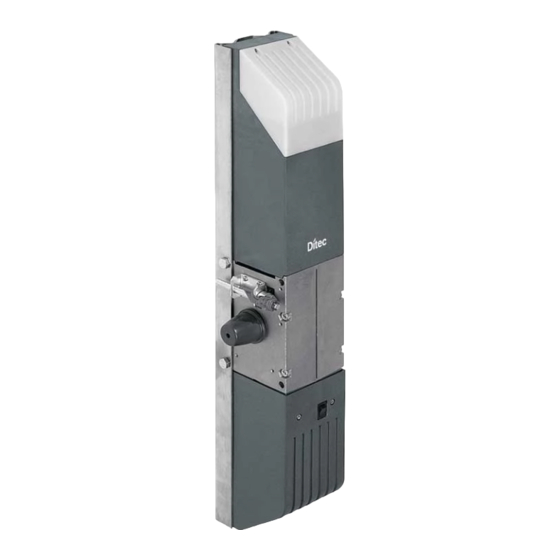
3. Dimensions 4. Main components Ref. Code Description Gearmotor Courtesy light Casing Bottom casing Manual release Gearmotor shaft Base plate BOXSL Base platee L=2500 E1HBOX BOX3EH’s control panel Control panel support Control panel casing... -
Page 10: Installation
5. Installation The given operating and performance features can only be guaranteed with the use of DITEC accessories and safety devices.Unless otherwise specified, all measurements are expressed in millimetres (mm). 5.1 Preliminary checks Check the dimensions, balancing and condition of the door, the type of installation, the use limits of the gearmotor and the necessary accessories. - Page 11 Standard balancing door Totally concealing balancing door Articulated panel balancing door...
-
Page 12: Geared Motor Installation
5.3 Geared motor installation - Fix the gearmotor to the base plate and the accessories as shown in the examples. 3400 max BoxB2D BoxB2C BoxRCG BoxRCG Box3EH BoxB2D BoxB2C BoxRCG Box3EH BoxB2D BoxB2D BoxB2C BoxB2C Box3EH Box3EH... - Page 13 BoxB2D 2700 max BoxB2C BoxRCG Box3EH For up and over doors with L>2700mm, it is necessary to extend the transmission shaft, using the accessories BOXA (pole) and BOXG (coupling for poles). If the arms are not long enough, use the extensions BOX2P. [1] Fix the corner-joint [A] onto the upper frame of the up and over door, in line with the motor arm.
-
Page 14: Installing The Left-Hand Gearmotor
5.4 Installing the left-hand gearmotor In the event of left-hand side assembly, it is necessary to rotate the gearmotor 180° so that the release shaft is pointing towards the centre of the up and over door. 180° [1] Disassemble the snap ring, unthread the lever and disassemble the upper bracket. [2] Rotate the gearmotor 180°. -
Page 15: Manual Release
5.5 Manual release To release the gearmotor from the outside, drill a Ø13 hole in the tilting door in line with the release pin A and release using the supplied key. NOTE: The gearmotor can also be released using the BOXSBC accessories. For more in- formation, refer to the relevant installation manuals. -
Page 16: Electrical Connections
6. Electrical connections NOTE: the electrical wiring and the start-up of the gearmotors are shown in the control panel installation manuals. Before connecting the power supply, make sure that the data on the plate correspond to the elec- tricity distribution network data. Provide an omnipolar switch/disconnector on the power network with a contact opening distance of 3 mm or more. -
Page 17: Automation Closure
7. Automation closure - Insert the casing [9] and fix it using the supplied screws. - Screw the bulb into the bulb support. - Fix the courtesy light casing [8] using the supplied screws. - Drill a hole in the control panel casing for the wiring. Fix the cable gland fastening bracket. -
Page 18: Operating Instructions
Operating instructions General safety precautions for the user ATTENTION! Important safety instructions • Please follow these instructions carefully • Failure to observe the information given in this manual may lead to severe personal injury or damage to the equipment • Keep these instructions for future reference. - Page 19 sensorial or mental abilities, or lack of experience or knowledge, as long as they are properly supervised or have been instructed in the safe use of the device and the relative hazards • Children must be supervised to make sure they do not play with the device, nor play or remain in the area of action of the motorized door or gate.
-
Page 20: Manual Release Instructions
Manual release instructions In the event of a fault or an interruption in the power supply, insert the key supplied [C] and turn it anticlockwise, or move the lever [D] as shown in the figure. Move the tilting door manually. To block the up and over door again, bring the lever [D] back to its original position.
Need help?
Do you have a question about the BOX and is the answer not in the manual?
Questions and answers