Subscribe to Our Youtube Channel
Summary of Contents for DITEC CROSS18
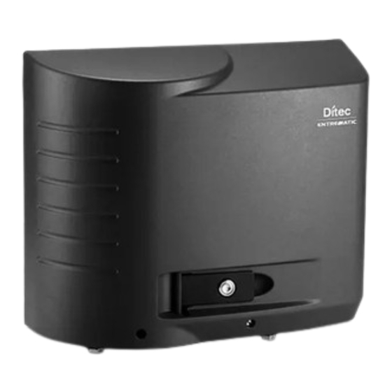
- Page 1 Last version of this manual IP2378EN•2023-06-29 Ditec CROSS18-20 Technical Manual Automation for sliding gates (translation of the original instructions) www.ditecentrematic.com www.ditecautomations.com...
-
Page 2: Table Of Contents
Index General safety precautions ............................3 Declaration of incorporation of partly completed machinery ..................4 UK Declaration of Conformity ............................5 Technical data ..............................6 Operating instructions ............................. 9 Machinery Directive ..............................9 Installation type ............................... 10 Dimensions ..............................11 Main components ............................. -
Page 3: General Safety Precautions
General safety precautions ATTENTION! Important safety instructions.Please follow these instructions carefully. Failure to observe the information given in this manual may lead to severe personal injury or damage to the equipment.Keep these instructions for future reference. This manual and those for any accessories can be downloaded from www.ditecautomations.com This installation manual is intended for qualified personnel only •... -
Page 4: Declaration Of Incorporation Of Partly Completed Machinery
Ditec CROSS18EP Sliding gate automations with electromechanical limit switches Ditec CROSS18VEP Sliding gate automations with magnetic limit switches Ditec CROSS20VEI Sliding gate automations with inverter and magnetic limit switches complies with the following directives and their amendments: 2006/42/EC Machinery Directive (MD), regarding the following essential health and safety require- ments: 1.1.2, 1.1.3, 1.2.1, 1.2.2, 1.2.3, 1.2.4.2, 1.2.6, 1.3.9, 1.4.3, 1.7.2, 1.7.3, 1.7.4, 1.7.4.1,... -
Page 5: Declaration Of Conformity
Ditec CROSS18EP Sliding gate automations with electromechanical limit switches Ditec CROSS18VEP Sliding gate automations with magnetic limit switches Ditec CROSS20VEI Sliding gate automations with inverter and magnetic limit switches Comply with the following directives and their amendments: • Supply of Machinery (Safety) Regulations 2016 •... -
Page 6: Technical Data
1. Technical data Ditec CROSS18EP Ditec CROSS18VEP Ditec CROSS20VEI Power supply 230 V~ 50 Hz 230 V~ 50/60 Hz Power input 3.5 A Motor type 230 V~ 230 V 3~ Thrust 1800 N 2000 N Gate speed 0.2 m/s 0,1 - 0,3 m/s... - Page 7 Chart. 1.1 Cycles / hour Ditec CROSS18EP/VEP and Ditec CROSS20VEI - T= 25°C) Default speed of 20 cm/s Ditec CROSS20VEI Ditec CROSS18EP/VEP lunghezza anta [m] Gate wing width [m] Chart. 1.2 Continuous cycles Ditec CROSS18EP/VEP and Ditec CROSS20VEI - T= 25°C)
- Page 8 OB/CB speed setting lower than the default values R1/R2/DT/RF/r1/r2 force setting higher than the default values R1/R2/DT force setting higher than the default values Chart 1.3 Product lifespan - Ditec CROSS18EP/VEP Product lifespan - Ditec CROSS20VEI 475.000 350.000 450.000 325.000 425.000...
-
Page 9: Operating Instructions
1.1 Operating instructions USE: for condominium, industrial and commercial, car park entrances with heavy driveway or pedestrian use. - Not suitable for gates or doors incorporating pedestrian auxiliary doors. - The class of service, usage times and number of consecutive cycles are suggestions. They are statistically measured under average usage conditions and cannot be certain for every single case. -
Page 10: Installation Type
2. Installation type Ref. Code Description Cable Ditec CROSS18EP 230 V gear motor with lever limit switch/built-in electronic control panel Ditec CROSS18VEP 230 V gear motor with magnetic limit switch/built-in electronic control panel 3G x 1.5 mm² Ditec CROSS20VEI 230 V gear motor with magnetic limit switch/built-in electronic control panel... -
Page 11: Dimensions
Pinions Lever limit switch unit magnetic limit switch unit 5. Installation Guaranteed operation and stated performance can only be achieved with DITEC accessories and safety devices. All measurements shown are in mm, unless otherwise indicated. 5.1 Preliminary checks Check the stability of the wing (derailment and side falls) and the condition of the running wheels and that the upper guides do not create friction. -
Page 12: Base Plate Preparation
5.2 Base plate preparation - Insert the anchor bolts on the base plate and secure them with the nuts supplied. - Prepare a concrete pad with the anchor bolts and base plate embedded in it, which must be level and clean, in accordance with the measurements shown in the figure. NOTE: If the concrete pad is already in place, the base plate can be fixed using M12 plugs (not supplied by us) to allow for height adjustment X+20 [*]... -
Page 13: Rack Installation
5.4 Rack installation - Unlock the gear motor (see INSTRUCTIONS FOR USE) and move the gate to the open position. - Place the rack on the pinion and, by sliding the gate manually, secure it along its entire length. - After fastening, adjust the gear motor vertically so that there is a gap of approximately 2-3 mm between the pinion and rack - Securely lock the gear motor. -
Page 14: Electrical Connections
6. Electrical connections CROSS18EP CROSS18VEP CROSS20VEI Electronic panel LCA85 LCA85 LCU43A Before connecting the power supply, make sure that the data on the plate correspond to the electricity distribution network data. Provide an omnipolar switch/disconnector on the power network with a contact opening distance of 3 mm or more. Check that there is a suitable residual- current device and surge protector upstream of the electrical system. - Page 15 Closing limit Opening limit Finecorsa Finecorsa Chiude switch Apre switch Release Microswitch AUX T di sblocco switch SCHEDA AD INNESTO 0 SW 0 11 0 12 PLUG-IN BOARD AUX1 SCHEDA AD INNESTO PLUG-IN BOARD AUX2 Antenna RADIO RX AUX2 AUX1 Output Uscita 24 V Safety stop...
-
Page 16: Apply Manual Release Label
7. Apply manual release label 8. Routine maintenance plan Carry out the following operations and checks every 6 months, depending on the how much the automation system is used. Switch off the 230 V~ power supply and unlock the gear motor: - Visually check that the gate, the fixing brackets and the existing structure have the necessary mechanical strength and are in good condition.


Need help?
Do you have a question about the CROSS18 and is the answer not in the manual?
Questions and answers