Sign In
Upload
Download
Table of Contents
Contents
Add to my manuals
Delete from my manuals
Share
URL of this page:
HTML Link:
Bookmark this page
Add
Manual will be automatically added to "My Manuals"
Print this page
×
Bookmark added
×
Added to my manuals
Manuals
Brands
DITEC Manuals
Gate Opener
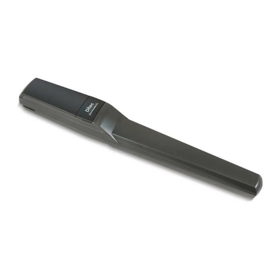
PWR25H
Technical manual
DITEC PWR25H Technical Manual
Automation for hinged gates
Hide thumbs
1
Table Of Contents
2
3
4
5
6
7
8
9
10
11
12
13
14
15
16
17
18
page
of
18
Go
/
18
Contents
Table of Contents
Troubleshooting
Bookmarks
Table of Contents
Table of Contents
General Safety Precautions
Declaration of Incorporation of Partly Completed Machinery
1 Technical Specifications
2 Standard Installation
3 Gearmotor Dimensions and References
4 Installation
Preliminary Checks
Bracket Fastening
Positioning Usage
Gearmotor Installation
Adjusting the Mechanical End Stops
Electrical Connections
Magnetic Limit Switches Adjustment (PWR35H Only)
5 Routine Maintenance Plan
Maintenance Every 6 Months or 10,000 Cycles
Maintenance Every 12 Months or 20,000 Cycles (PWR35H Only)
6 Troubleshooting
Advertisement
Quick Links
Download this manual
IP2250EN • 2021-09-16
Technical Manual
Ditec PWR25H/35H
Automation for hinged
gates
(translation of the original instructions)
www.ditecautomations.com
Table of
Contents
Previous
Page
Next
Page
1
2
3
4
5
Advertisement
Table of Contents
Need help?
Do you have a question about the PWR25H and is the answer not in the manual?
Ask a question
Questions and answers
Related Manuals for DITEC PWR25H
Gate Opener DITEC PasM24T User Manual
Selfmonitored motion sensor for automatic escape doors (42 pages)
Gate Opener DITEC PWR35H Technical Manual
Automation for hinged gates (18 pages)
Gate Opener DITEC PAS024AMR Installation Manual
Opening & safety sensor for automatic sliding doors in emergency exits (8 pages)
Gate Opener DITEC CUBIC6 Installation And Maintenance Manual
Swing gates (16 pages)
Gate Opener DITEC OBBI3BH Maintenance Manual
(16 pages)
Gate Opener DITEC CS 61E Installation And Maintenance Manual
Sliding gate automatic system (10 pages)
Gate Opener DITEC Entrematic FACIL3H Original Instructions Manual
(20 pages)
Gate Opener DITEC Homelink GLOBE IP1839 Installation And Maintenance Manual
(65 pages)
Gate Opener DITEC CROSS18 Technical Manual
Sliding gates automation (20 pages)
Gate Opener DITEC SECTOR RESET Installation, Use And Maintenance Manual
Roll-up high speed door with counter weight (52 pages)
Gate Opener DITEC CROSS8E-E1A Quick Reference
(3 pages)
Gate Opener DITEC Cross14 Installation And Maintenance Manual
(10 pages)
Gate Opener DITEC QIK7EH-73R Quick Reference
(3 pages)
Gate Opener DITEC CROSS3E-73R Quick Reference
(4 pages)
Gate Opener DITEC Arc Series Installation And Maintenance Manual
Swing gates (25 pages)
Gate Opener DITEC CROSS18 Technical Manual
Automation for sliding gates (16 pages)
This manual is also suitable for:
Pwr35h
Table of Contents
Print
Rename the bookmark
Delete bookmark?
Delete from my manuals?
Login
Sign In
OR
Sign in with Facebook
Sign in with Google
Upload manual
Upload from disk
Upload from URL


Need help?
Do you have a question about the PWR25H and is the answer not in the manual?
Questions and answers