
Related Manuals for DITEC FACIL Series


Summary of Contents for DITEC FACIL Series
- Page 1 Last version of this manual IP2132EN•2023-05-03 Ditec FACIL Technical Manual Swing gates automation (translation of the original instructions) www.ditecautomations.com...
-
Page 2: Table Of Contents
Index General safety precautions .......................... 25 Declaration of incorporation of partly completed machinery .................. 26 UK Declaration of Conformity .......................... 27 Technical data .............................. 28 Operating instructions ..........................29 Machinery Directive ..........................29 Standard installation .......................... 30 Dimensions .............................. 31 Installation .............................. -
Page 3: General Safety Precautions
General safety precautions ATTENTION! Important safety instructions.Please follow these instructions carefully. Failure to observe the information given in this manual may lead to severe personal injury or damage to the equipment.Keep these instructions for future reference. This manual and those for any accessories can be downloaded from www.ditecautomations.com This installation manual is intended for qualified personnel only •... -
Page 4: Declaration Of Incorporation Of Partly Completed Machinery
SE-261 44 Landskrona Sweden, declare, under our sole responsibility, that the type of equipment with the name: Ditec FACIL Automation for swing gates complies with the following directives and their amendments: 2006/42/EC Machinery Directive (MD), regarding the following essential health and safety requirements: 1.1.2, 1.1.3, 1.2.1, 1.2.2, 1.2.3, 1.2.4.2, 1.2.6, 1.3.9, 1.4.3, 1.7.2, 1.7.3, 1.7.4, 1.7.4.1, 1.7.4.2. -
Page 5: Declaration Of Conformity
Lodjursgatan 10 SE-261 44 Landskrona Sweden Declare under our sole responsibility that the types of equipment with names: Ditec FACIL Automation for swing gates complies with the following directives and their amendments: • Supply of Machinery (Safety) Regulations 2016 • Electromagnetic Compatibility Regulations 2016 •... -
Page 6: Technical Data
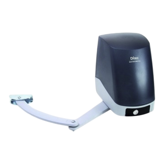
1. Technical data FACIL3H FACIL3EH Power supply 24 V 230 V~ 50/60 Hz Absorption 0,6 A Torque 200 Nm Opening time 12÷32 s / 90° Maximum weight 300 kg Leaf width (max) 2,3 m Max. opening 110° 3 - FREQUENT Service class (tested up to 150.000 cycles) S2= 30 min (T= 25°C) -
Page 7: Operating Instructions
1.1 Operating instructions Use: FREQUENT (for vehicle or pedestrian for single-family or multi-family with frequent use). - Performance characteristics are to be understood as referring to the recommended weight (ap- prox. 2/3 of maximum permissible weight). A reduction in performance is to be expected when the access is made to operate at the maximum permissible weight. -
Page 8: Standard Installation
2. Standard installation Ref. Code Description Cable Connector block (not supplied). Connect the power supply to an approved omnipolar switch with an opening distance of the contacts of at least 3mm (not supplied). The connection to the mains must be made via an independent channel, separated from the connections to command and safety devices. -
Page 9: Dimensions
3. Dimensions... -
Page 10: Installation
4. Installation The given operating and performance features can only be guaranteed with the use of DITEC ac- cessories and safety devices. Unless otherwise specified, all measurements are expressed in mm. 4.1 Preliminary checks Check that the structure is sufficiently rugged and that the hinge pivots are properly lubricated. -
Page 11: Bracket Fastening
4.2 Bracket fastening - Securely fix the fastening plate [8] to the gate pillar and the arm retention bracket [13] to the leaf as indicated in figure. Ø 8,5 Ø 8,5... -
Page 12: Gearmotor Installation
4.3 Gearmotor installation Remove the lid [7] and fit the gearmotor [9] to the fastening plate [8] as indicated in figure. Release the gearmotor (see use instructions). LCU30H (integrated) BOXFC1 (optional) - Fix the articulated arms and the arm retention bracket [10] as indicated in figure. - The arm articulations must be lubricated and the screws sufficiently tightened so that they do not impede the movement of the arms. -
Page 13: Limit Switch Installation And Adjustment (Optional)
4.4 Limit switch installation and adjustment (optional) - Connect the limit switch wire fastons to the microswitches. Arrange the limit switch wires neatly inside the microswitch box [1] and route the wire out through the appropriate opening. - Fit the two cams [3] on to the cam ring without tightening the screws. - Install the cam ring on the driving shaft and screw down screw [4] without tightening. -
Page 14: Electrical Connections
For the correct assembly of the limit switches, see the relative technical documentation BOXFC1 - IP1596: https://www.ditecautomations.com/global/market-documents/QR/Multilanguages/ACCESSORIES/ GA/Ditec_BOXFC1_technical-manual_IP1596.pdf 5. Electrical connections NOTE: the electrical wiring and the start-up of the gearmotors are shown in the control panel installation manuals. Before connecting the power supply, make sure that the data on the plate correspond to the elec- tricity distribution network data. - Page 15 For complete control panel instructions see manual LCU40H-HJ - IP2246: https://www.ditecautomations.com/global/market-documents/QR/Multilanguages/LCU40H/DitecLCU40H.pdf For complete control panel instructions see manual LCU30H-HJ - IP2251: https://www.ditecautomations.com/global/market-documents/QR/Multilanguages/LCU30H/DitecLCU30H.pdf...
-
Page 16: Routine Maintenance Plan
6. Routine maintenance plan Perform the following operations and checks every 6 months according to intensity of use of the automation. Without 230 V~ power supply and batteries if present: - Clean and lubricate the gate’s rotation pins and hinges with neutral grease. - Check the resistance of the fixing points. -
Page 17: Operating Instructions
Operating instructions General safety precautions for the user ATTENTION! Important safety instructions • Please follow these instructions carefully • Failure to observe the information given in this manual may lead to severe personal injury or damage to the equipment • Keep these instruc- tions for future reference. - Page 18 height of 1.5 m, and out of reach of the public • The motorized door or gate may be used by children over the age of 8 and by people with reduced physical, sensorial or mental abilities, or lack of experience or knowledge, as long as they are properly supervised or have been instructed in the safe use of the device and the relative hazards •...
-
Page 19: Manual Release Instructions
Manual release instructions In the event of a fault or a power failure, introduce the key, turn it clockwise and fully open the hatch. Manually open the gate. To lock the gate again, close the hatch, turn the key anticlockwise and remove the key NOTE: to turn off the automation the power supply and batteries (if present) must be disconnected. - Page 20 All the rights concerning this material are the exclusive property of ASSA ABLOY Entrance Systems AB. Although the contents of this publication have been drawn up with the greatest care, ASSA ABLOY Entrance Systems AB cannot be held responsible in any way for any damage caused by mistakes or omissions in this publication. We reserve the right to make changes without prior notice.
Need help?
Do you have a question about the FACIL Series and is the answer not in the manual?
Questions and answers