
Related Manuals for Wren Vogue 300


Summary of Contents for Wren Vogue 300
- Page 1 BASE UNIT 300-600, 1 Door Assembly Guide 300 Base Unit 400 Base Unit 450 Base Unit 500 Base Unit 500 Bin Base Unit 600 Base Unit (with lids) 600 Bin Base Unit (with metal shelf) For Internal Use: FI.WR.INS.020_WKIN00102_BASE_300-600_1Dr_Rev8...
-
Page 2: Before You Start
BASE UNIT 300 - 600, 1 Door Assembly Guide BEFORE YOU START INSTALLATION SHOULD BE PERFORMED BY A COMPETENT PERSON ONLY. THIS PRODUCT COULD BE DANGEROUS IF INCORRECTLY INSTALLED NOT to be used with CAM LOCK Page 2 For Internal Use: FI.WR.INS.020_WKIN00102_BASE_300-600_1Dr_Rev8... - Page 3 BASE UNIT 300 - 600, 1 Door Assembly Guide Panel A Panel B Panel C Panel D Shelf Frontal x2 End Panel x1 Back Panel x1 Base Panel x2 Rail x1 Loose Shelf x1 Front Panel (Packed Separately) Page 3 For Internal Use: FI.WR.INS.020_WKIN00102_BASE_300-600_1Dr_Rev8...
- Page 4 BASE UNIT 300 - 600, 1 Door Assembly Guide (F) x12 (L) x28 (K) x7 (G) x8 (H) x8 Wooden 15mm 30mm Cam Lock Cam Dowel Dowel Screw Screw (Expanding) (M) x4 L Bracket Space Plug (Z) x4 (N) x1 Cover Cap Shelf Peg Metal Door Buffer...
- Page 5 BASE UNIT 300 - 600, 1 Door Assembly Guide Step 1. Seat dowels (F) into holes in both end panels (A) as shown. Page 5 For Internal Use: FI.WR.INS.020_WKIN00102_BASE_300-600_1Dr_Rev8...
- Page 6 BASE UNIT 300 - 600, 1 Door Assembly Guide Step 2. Seat expanding cam dowels (G) into holes in both end panels (A) as shown. Page 6 For Internal Use: FI.WR.INS.020_WKIN00102_BASE_300-600_1Dr_Rev8...
- Page 7 BASE UNIT 300 - 600, 1 Door Assembly Guide Step 3. Attach panels (C) & (D) to panels (A), using expanding cam dowels (G), and wooden dowels (F) in positions as shown. All cam lock (H) holes are to be positioned facing the outside of the unit carcase, for ease of tightening.
- Page 8 BASE UNIT 300 - 600, 1 Door Assembly Guide Step 4. Slide back panel (B) into groove of end panels (A). Once back panel (B) is in position, ensure the panel is flush & square with bottom of end panels. For the bin installation.
- Page 9 BASE UNIT 300 - 600, 1 Door Assembly Guide Step 5. Insert cam locks (H) and hand tighten them, this will expand cam dowels (G) and tighten the unit together. Do not use power tools with cam lock (H) Page 9 For Internal Use: FI.WR.INS.020_WKIN00102_BASE_300-600_1Dr_Rev8...
- Page 10 BASE UNIT 300 - 600, 1 Door Assembly Guide Step 6. Ensure the unit is square. Secure back panel (B) with 3 x 30mm screws (K) equally spaced at the bottom of back panel (B) into base panel (C), as shown. Ensure you screw into the centre of the base panel (C) (9mm from the edge).
- Page 11 BASE UNIT 300 - 600, 1 Door Assembly Guide Step 7. Position legs as shown on the diagram below. Ensure legs are rotated to also provide support to the end panels (A). Once positioned, secure each of the legs into place with 4 x 15mm screws (L) per leg.
- Page 12 BASE UNIT 300 - 600, 1 Door Assembly Guide Step 8. Attach hinge plates onto end panel (A) as shown, using 2 screws already located in hinge plates. Hinge side to be mounted in accordance to customer specific kitchen plan. From top 94mm 126mm...
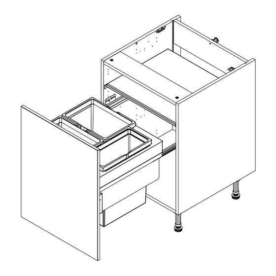
- Page 13 BASE UNIT 300 - 600, 1 Door Assembly Guide 500 & 600 Bin Base Unit Please refer to separate instruction included with your 600 bin. 500 Bin Base Unit 600 Bin Base Unit Page 13 For Internal Use: FI.WR.INS.020_WKIN00102_BASE_300-600_1Dr_Rev8...
- Page 14 BASE UNIT 300 - 600, 1 Door Assembly Guide Screws for attaching to walls and worktops are not provided as these vary depending on materials, thickness and construction. Ensure appropriate fixings for wall and worktop construction are used. Please refer to the specialist worktop supplier if these are required for solid surface worktops. Step 9.
- Page 15 BASE UNIT 300 - 600, 1 Door Assembly Guide HINGE ATTACHMENT AND ADJUSTMENT Step 1. Insert hinges into frontal hinge holes provided, secure hinges with Hinge dowels the 2 x screws and hinge dowels already located in the hinges. Step 2. Attach the door to unit, clip hinges onto hinge plates and click to secure.
Need help?
Do you have a question about the Vogue 300 and is the answer not in the manual?
Questions and answers