
Subscribe to Our Youtube Channel
Related Manuals for KYORITSU KEW6024PV


Summary of Contents for KYORITSU KEW6024PV
-
Page 1: Instruction Manual
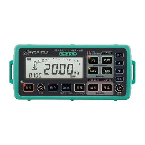
Instruction manual PV insulation earth tester KEW6024PV .800.561.8187 information@itm.com www. .com... -
Page 2: Table Of Contents
Contents 1. Safety warnings ................... 1 2. Features ....................7 3. Specifications ..................9 4. Name of parts ..................14 5. Accessories ..................19 6. Preparations for measurement ............21 6-1 Battery voltage check ..............21 6-2 Attaching metal tip/ adapter to test leads ........21 7. - Page 3 12. Memory function ................49 12-1 How to save ................50 12-2 How to recall ................52 12-3 How to delete ................53 13. System clock settings ..............54 13-1 How to adjust ................54 14. Data communication function ............56 14-1 How to transfer data ..............
-
Page 4: Safety Warnings
1. Safety warnings This instrument has been designed, manufactured and tested according to IEC 61010: Safety requirements for Electronic measuring apparatus, and delivered in the best condition after passing quality control tests. This instruction manual contains warnings and safety rules which have to be observed by the user to ensure safe operation of the instrument and to maintain it in safe condition. - Page 5 Measurement category To ensure safe operation of measuring instruments, IEC 61010 establishes safety standards for various electrical environments, categorized as O to CAT IV, and called measurement categories. Higher-numbered categories correspond to electrical environments with greater momentary energy, so a measuring instrument designed for CAT III environments can endure greater momentary energy than one designed for CAT II.
- Page 6 DANGER ● The instrument is to be used only in its intended applications or conditions. Otherwise, safety functions equipped with the instrument don’t work, and instrument damage or serious personal injury may occur. ● Verify proper operation on a known source before taking actions as a result of the indication of the instrument.
- Page 7 Understand and follow all the safety instructions contained in the manual. Failure to follow the instructions may cause injury, instrument damage and/or damage to the equipment under test. Kyoritsu is by no means liable for any damage resulting from the instrument in contradiction to these cautionary notes.
- Page 8 CAUTION ● Select an appropriate function before starting a measurement. ● Power off the instrument after use, and disconnect the test leads. Remove batteries if the instrument is to be stored and will not be in use for a long period. ●...
- Page 9 Symbols marked on the instrument Primary electrical circuits of the equipment connected CAT III directly to the distribution panel, and feeders from the distribution panel to outlets The circuit from the service drop to the service CATIV entrance, and to the power meter and primary over-current protection device (distribution panel) Instrument with double or reinforced insulation User must refer to the explanations in the instruction...
-
Page 10: Features
2. Features KEW6024PV can measure insulation resistances of PV systems with open voltages of 1000 V or less and of low-voltage installations with voltages of 600 V or less; moreover, earth resistance and AC/ DC voltage of distribution lines and electrical appliances. - Page 11 ● Insulation resistance measurement - When insulation resistance like a capacitive load is measured, electric charges stored in a capacitive circuit are automatically discharged after measurement. Discharge can be checked with the live warning LED, red backlight, blinking symbol on the LCD and buzzer. - Bar graph display - Buzzer beeps when the measured value drops below or exceed the pre-set threshold value.
-
Page 12: Specifications
3. Specifications ● Measuring range and accuracy (23ºC±5ºC, RH 75% or less) PV insulation resistance measurement Rated measurement 500V 1000V voltage (DC) Range 20/ 200/ 2000MΩ (3-range auto) 20MΩ range : 0.00 - 19.99 MΩ Display range 200MΩ range : 15.0 - 208.9 MΩ 2000MΩ... - Page 13 Voltage/ Earth voltage measurement Measuring range Display range (2-range auto) Accuracy 5 to 600 V AC 300V range: 0.0 to 314.9 V (45 - 65Hz) 600V range: 240 to 629 V ±1%rdg±4dgt 500V range: 0.0 to ±524.9 V ±5 to ±1000 V DC 1000V range: ±400 to ±1049 V Measuring method: True RMS * Automatically detect AC/ DC when an input voltage is 5 V or higher and...
- Page 14 Insulation resistance measurement Rated measure- 250V 500V 1000V ment voltage (DC) Range 20/ 200/ 2000MΩ (3-range auto) 20MΩ range : 0.00 - 20.99 MΩ Effective display 200MΩ range : 16.0 - 209.9 MΩ range 2000MΩ range : 160 - 2099 MΩ Open-circuit Rated measurement voltage x 1 - 1.2 times voltage (DC)
- Page 15 Complies with the following standards: ● IEC 61010-1, -2 -030 CAT III 600V, CAT IV 300V Pollution degree 2 ● IEC 61557-1, -2, -5, -10 ● IEC 60529 IP54 (MODEL7196A/ IP40, MODEL7243/ IP42) ● IEC 61326-1, -2-2 Class B ● IEC 61010-031 MODEL7196A ..CAT III 1000V, CAT IV 600V MODEL7244A ..
- Page 16 ● Operating uncertainty Operating uncertainty (B) is an error obtained under the nominal operating conditions, and calculated with the intrinsic error (A), which is an error of the instrument used, and the error (En) due to variations. According to IEC61557, the maximum operating error should be within ± 30%. * Formula: �...
-
Page 17: Name Of Parts
● Possible number of measurements where battery voltage is within the effective range (measurement of 5 sec., pause of 25 sec.) Test Possible number of Function resistor measurements PV Insulation 500V 0.5 MΩ Approx. 2500 times resistance 1000V 1 MΩ Approx. - Page 18 (2) Panel side ⑰ ⑯ ⑮ ⑭ ① ⑬ ⑫ ⑪ ⑧⑨ ② ⑩ ③ ④ ⑤ ⑥ ⑦ Fig. 4-1 (3) Terminal part (Connector block) ⑱ ⑲ ⑳ Fig. 4-2 - 15 - ̶ 15 ̶ .800.561.8187 information@itm.com www. .com...
- Page 19 Items – Panel side Description LCD with backlight ① Test button Starts/ stops a continuous measurement ② Backlight button Turns on/ off the backlight ③ Save button Saves the measured result ④ Read/ delete button Reads out or deletes the saved data ⑤...
- Page 20 (4) LCD ● Symbols common to all functions Battery level indicator Bar graph (For PV insulation, insulation, earth measurements) Segments for numerical display Indicates “Over-range” status – the measured value is exceeding the positive display limit. e.g.: In earth measurements, “>2099Ω” may be displayed.
- Page 21 ● Symbols for PV/ ordinary insulation measurement Appears to indicate the selected rated measurement voltage * 500V/1000V are selectable for PV system Unit Appears if 1000V button is pressed where 1000 V is un-selectable. ● Symbols for earth measurement Appears to indicate the selected function ・...
-
Page 22: Accessories
5. Accessories ● Test leads (1) Test probe MODEL7196A with remote control switch (red) Fig. 5-1 Changeable metal tips are available for MODEL7196A. (2) CAT II standard prod MODEL8072 (3) Extension prod MODEL8017 …1 pce …1 pce Fig. 5-2 Fig. 5-3 Thin tip metal parts Long type and helpful to access the distant measurement spot... - Page 23 (10) Precision measurement cord set MODEL7245A (Optional accessory) (11) Test leads for precision (12) Auxiliary earth spike measurement MODEL7228A MODEL8032 Red 20m Yellow 10m Green 5m 215mm(L)×110mm(W) *A pair of two spikes Fig. 5-9 Fig. 5-10 + (14) Cord reel (3 pcs) (13) Carrying bag MODEL8200-03 MODEL9142...
-
Page 24: Preparations For Measurement
6-1 Battery voltage check (1) Please refer to “15. Battery replacement” in this manual and insert batteries in KEW6024PV. (2) Hold down the Power button at least 1 sec and power on the instrument. * A long press of 1 sec or longer is required to power on/ off the instrument in order to prevent a malfunction. - Page 25 [How to replace the parts] Detach the tip of Line probe by turning it counter-clockwise. Insert the metal tip you want to use into the hexagon hole, and turn the tip part of the probe clockwise to tighten firmly. Note: Molded standard metal parts should be used in CAT III or IV environment.
-
Page 26: Insulation Resistance Measurement On Pv Systems
7. Insulation resistance measurement on PV systems Measure the insulation resistance of PV system to verify insulation of PV array/ string. Before starting a measurement, confirm the voltage value which can be applied to the object under test. Note: ● Insulation resistance of PV array may be low if it is measured in rain or high humidity. - Page 27 DANGER ● Be extremely careful not to touch the tip of test probe or circuit under test to avoid electrical shock during insulation resistance measurement as high voltage is present on the tip of the test probe continuously. ● Wipe the test probe with a soft cloth, if it is wet, and use it after it’s dry. ●...
-
Page 28: Measuring Method
7-1 Measuring method DANGER ● Do not measure PV arrays with open-circuit voltage of 1000 V or more. CAUTION ● Test and verify the insulation of P terminal prior to measuring insulation resistance between N and earth terminals of PV array. If the measured resistance value is low, do not perform further measurement so as not to damage solar cells and modules. - Page 29 (3) Follow the procedures described on the next page and open-circuit the circuit to be measured. Fig. 7-2 CAUTION This is just an example and the PV system connection may be different from actual one. Always check the actual connection before starting measurement.
- Page 30 1. Turn off the main switch of the solar PV installation following the procedures according to the PV installation or solar Inverter instruction manual. 2. Turn off all disconnection switches and disconnect each string. 3. In case of presence of SPDs (Surge Protection Devices) they must be disconnected during all testing.
- Page 31 (5) Connect the earth test lead (MODEL7244A) to the earth terminal of the circuit under test. Then, place the tip of remote probe (line) to P terminal of the string. Confirm that the voltage in the circuit under test is not high (usually less than 50V).
- Page 32 (6) Press the TEST button or remote control switch to start a continuous measurement. Note: Sometimes the insulation resistance value takes long time until becomes stable because the string capacitance is big. It is possible to relatively compare the insulation resistance value of each string taking the reading after 1 minute of testing, so without waiting for long time until the value is stable.
- Page 33 (8) [Auto discharge function] This function allows electric charges stored in the capacitance of the circuit under test to be automatically discharged after measurement. Set the TEST button or remote control switch to off with the test leads connected. Discharge can be monitored by the readings displayed at the lower left of the LCD and also by live circuit warning LED, red backlight and blinking mark.
-
Page 34: Insulation Resistance Measurement
8. Insulation resistance measurement This instrument is used to measure insulation resistance in electric appliance or circuit to inspect the insulation performance. Check the voltage rating of the object to be tested before making measurement and select the voltage applied to. Note: ●... -
Page 35: Measuring Method
8-1 Measuring method (1) Press the PV button to select insulation measurement function. The LCD shows “InSU” for about one second, and the PV LED turns off. (2) Connect the test leads as Fig. 8-1 shows. MODEL7196A to LINE terminal, and MODEL7244A to EARTH terminal Fig. - Page 36 CAUTION ● Always disconnect power to the conductor under test before starting insulation measurement. Do not attempt to make measurements on a live conductor. Otherwise, it may damage the instrument. Power Display example Earth terminal Switch Black Fig. 8-2 Load Principle of insulation resistance measurement LINE(-)
- Page 37 (5) [Auto discharge function] This function allows electric charges stored in the capacitance of the circuit under test to be automatically discharged after measurement. Set the TEST button or remote control switch to off with the test leads connected. Discharge can be monitored by the readings displayed at the lower left of the LCD and also by live circuit warning LED, red backlight and blinking mark.
- Page 38 (7) Output voltage characteristics This instrument conforms to IEC61557-2. This standard specifies that the rated current shall be at least 1 mA and thus defines the lower limit of the insulation resistance to maintain the rated voltage at the measurement terminal.
-
Page 39: Earth Resistance Measurement
9. Earth resistance measurement With the earth resistance measurement function of this instrument, earth resistance of power distribution lines, in-house wiring system and electrical appliances can be measured. DANGER ● The instrument will produce a maximum voltage of about 50 V between C (H) and E terminals at earth resistance measurement. -
Page 40: Simplified Measurement
9-2 Simplified measurement Use this method when the auxiliary earth spike cannot be stuck. In this method, an existing earth electrode with a low earth resistance, such as a metal water pipe, a common earth of a commercial power supply and an earth terminal of a building, can be used with two-pole method (E and P). - Page 41 DANGER ● Use a voltage detector to check a common earth of commercial power supply. ● Do not use this instrument to check a common earth of commercial power supply. A danger will be caused because the voltage may not be displayed even in case of a live conductor, when the connection of the earth electrode to be measured has come off, or when the connection of the test leads of the instrument is not correct etc.
- Page 42 (4) Measurement ● Press TEST or the remote control switch to start a continuous measurement. Press TEST or remote control switch again to stop measurement. Display example Fig. 9-7 The LCD shows “>2099Ω” when the measured result exceeds the display range (over-range). (5) Simplified measurement value Two-pole method is used for simplified measurement.
-
Page 43: Precision Measurement (With Model7228A Test Leads)
9-3 Precision measurement (with MODEL7228A test leads) (1) Connection Switch the auxiliary earth spikes P(S) and C(H) into the ground deeply. They should be aligned at an interval of 5 - 10 m from the earthed equipment under test. Connect the green wire to the earthed equipment under test, the yellow wire to the auxiliary earth spike P(S) and the red wire to auxiliary earth spike C(H) from terminals E, P(S) and C(H) of the instrument in order. - Page 44 (2) Earth voltage check ● Press the 3POLE button and select precision measurement function. Then, 3POLE mark is displayed on the LCD. ● In the connection state of Fig. 9-10, check the earth voltage displayed on the LCD. The earth voltage displayed in this state is the voltage between P(S) and E terminals.
- Page 45 (3) Measurement Press TEST or the remote control switch to start a continuous measure- ment. Press TEST or remote control switch again to stop measurement. Display example Fig. 9-13 The LCD shows “>2099Ω” when the measured result exceeds the display range (over-range). (4) Auxiliary earth resistance If the auxiliary earth resistance is within the allowable range and doesn’t affect measurement, the LED (AUX.
- Page 46 DANGER ● If measurement is made with the test leads twisted or in touch with each other, the reading of the instrument may be affected by induction. When connecting the test leads, make sure that they are separated. ● If earth resistance of auxiliary earth spikes is too large, it may result in inaccurate measurement.
-
Page 47: Voltage Measurement
10. Voltage measurement DANGER ● Do not apply a voltage exceeding the maximum allowable input (600 V AC/ 1000 V DC) to the insteument and between terminals. 10-1 Measuring method (1) Press the VOLTS button to select voltage measurement function. (2) Connect the test leads as Fig. - Page 48 (4) Check the reading on the LCD without pressing TEST or remote control button. The instrument detects AC/ DC automatically, and shows “DC” for dc input and “AC” for ac input on the LCD. ● As for dc inputs, the negative polarity sign “-“ is displayed to the left of the reading where the line probe side is charged with negative polarity.
-
Page 49: Alarm Function
11. Alarm function 11-1 Alarm function Compare the measured result and the pre-set reference value on PV insulation measurement, insulation measurement and earth measurement functions and notify the result to the user with buzzer. Select any of the following reference values or enter a desired value. Different values can be set for each range. - Page 50 3. Press SET UP. 4. Press cursor button ( ) to select any reference value. Blink Fig. 11-3 (Select “Any” to enter a desired value.) Setting completes 5. Press SET UP. when selecting a reference value. When entering a desired value: 6.
-
Page 51: Display Example - Alarm Setting
11-3 Display example – Alarm setting Insulation measurement Earth measurement (stand-by state) (stand-by state) Fig. 11-8 Fig. 11-9 Alarm mark and the pre-set reference value are displayed while alarm function is enabled. When starting a PV insulation or earth resistance measurement, the alarm mark will only be displayed. -
Page 52: Memory Function
12. Memory function Results measured in PV insulation resistance, voltage, insulation resistance and earth resistance measurements can be saved in the memory of the instrument. (max. 1000) In addition, two different location numbers can be allocated to each data. Parameters saved Detail Range with the results... -
Page 53: How To Save
12-1 How to save 1. Confirm the measured value is held right after a measurement. Fig. 12-1 2. Press SAVE. (In case of voltage measurement, press SAVE during a measurement.) Site no.1 Blink Fig. 12-2 3. Press cursor button (△ or ▽) to set Site no 1. - Page 54 6. Press SET UP. 7. Press cursor button ( ) to Data no. set Data no. The displayed Blink number is the previous number plus one. Fig. 12-4 8. Press SET UP. Data save completes. Fig. 12-5 2 sec later Returns to the state at the beginning.
-
Page 55: How To Recall
12-2 How to recall Follow the procedures below to recall the saved data. Stand-by state 1. Stand by or data hold state. Fig. 12-7 2. Press RECALL. Data no. 3. Saved data is displayed. Press cursor button (△ or ▽) to Fig. -
Page 56: How To Delete
12-3 How to delete Follow the procedures below to delete the saved data. Stand-by state 1. Stand by or data hold state. Fig. 12-11 2. Hold down RECALL 2 sec. Long press of icon will then be displayed. 2 sec :Delete Hold down 3. -
Page 57: System Clock Settings
13. System clock settings To adjust the date and time of internal system clock, follow the steps below. When saving measured results in the internal memory, date and time information will be saved together. * Not the date and time when the measurement was performed. 13-1 How to adjust The following figures show how to set the system clock. - Page 58 5. Press SET UP. * Returns to the top of year setting. Month Blink 6. Press cursor button ( ) to adjust month. Previously adjusted year will be displayed at the lower left corner. Fig. 13-4 Year 7. Press SET UP. Blink 8.
-
Page 59: Data Communication Function
14. Data communication function Data transfer to PC is possible by using our optical adapter MODEL8212 USB. 14-1 How to transfer data (1) Install “KEW Report” first before trying to transfer data to PC. (2) Connect the plug of MODEL8212 USB to the USB port on the PC. (3) Disconnect the test leads from the instrument, and then connect MODEL8212 USB as follows. -
Page 60: Battery Replacement
15. Battery replacement When the battery indicator shows empty “ ”, replace the batteries with new ones. DANGER ● Do not open the battery compartment cover if the instrument is wet. ● Never attempt to replace batteries during a measurement. In order to avoid getting electrical shock, ensure that the instrument is powered off and test leads are disconnected from the instrument before replacing batteries. -
Page 61: Shoulder Strap And Soft Case Attachment
16. Shoulder strap and soft case attachment 16-1 How to attach shoulder strap (1) Run the side belt through the slider as Fig. 16-1 shows. (for two side belts) (2) Attach the side belt as Fig. 16-2 shows. Side belt (to both sides) Fig. -
Page 62: How To Attach Soft Case
16-2 How to attach soft case Put the instrument into the soft case as Fig. 16-4 shows. Follow the arrows with number 1 and 2 in sequence. Partition Instrument ② ① Soft case Fig. 16-4 (1) Run the side belts though the slits on the soft case, and put the instrument into the soft case.
Need help?
Do you have a question about the KEW6024PV and is the answer not in the manual?
Questions and answers