Advertisement
Advertisement
Table of Contents

Subscribe to Our Youtube Channel
Related Manuals for Digitus DN-80112-2


Summary of Contents for Digitus DN-80112-2
- Page 1 16/24-PORT GIGABIT SWITCH Quick Installation Guide DN-80112-2 DN-80113-2 ...
-
Page 2: Table Of Contents
Table of contents Introduction ..................3 Main feature ..................3 Package Content ................... 3 Specifications ..................4 Hardware Description ................5 Installation the Switch ................7 Turn on the switch ................9... -
Page 3: Introduction
1. Introduction DN-80112-2 has 16x10/100/1000Mbps RJ45 port, and DN-80113-2 has 24 10/100/1000 Mbps RJ45 ports, using store and forward technology, combined with dynamic memory allocation, to ensure the effective allocation of bandwidth to each port. This switch is easy to install and does not require configuration. -
Page 4: Specifications
4. Specifications Model DN-80112-2 DN-80113-2 IEEE802.3、 IEEE802.3i, IEEE802.3u、 Standard IEEE802.3ab、IEEE802.3x 10BASE-T: UTP category 3,4,5 cable (≤100m) Network Media 100BASE-TX: UTP category 5, 5e cable (≤100m) 1000BASE-T: UTP category 5, 5e cable (≤100m) MAC Address 8K, Auto-learning, Auto-aging Table Transfer mode... -
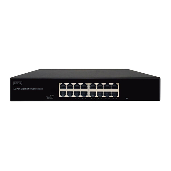
Page 5: Hardware Description
5. Hardware Description 5.1 Front Panel The Front Panel consists of Ethernet Ports. The LED indicators are also located on the panel. DN-80112-2 DN-80113-2 DIP Switch The DIP switch located on the left panel. Default: the factory default mode, can normal communication •... - Page 6 Note: No need to manually reboot to make the switch effective after changing settings (online toggle) LED indicator Color Function Off: No Power supply. Green Light: Indicates the switch has power. Off: No device is connected to the corresponding port. Light: Indicates the link through that port is successfully LNK/ACT Green established at 10/100/1000Mbps.
-
Page 7: Installation The Switch
Precautions: The product has provision for a permanently connected protective grounding conductor, this conductor need to install to building earth by a skilled person. 6. Installation the Switch This part describes how to install your Ethernet Switch and make connections to it. Please follow the following instructions in avoid of incorrect installation causing device damage and security threat. - Page 8 6.2 Rack-mountable Installation The switch is rack-mountable and can be installed on an EIA-19-inch equipment rack. To do this, first, please install the mounting brackets on the switch’s side panels (one on each side), secure them with the included screws, and then use the screws provided with the equipment rack to mount the switch on the 19-inch rack as example below.
-
Page 9: Turn On The Switch
7. Turn on the switch Please connect the AC power cord into the rear of the switch and to an electrical outlet (preferably one that is grounded). When the switch is power on, the LED indicators flash momentarily for one second, which represents a resetting of the system.
Need help?
Do you have a question about the DN-80112-2 and is the answer not in the manual?
Questions and answers