
Related Manuals for CommScope FDH 5000 432


Summary of Contents for CommScope FDH 5000 432
- Page 1 Installation Instructions TC-1568-IP Rev B, June 2024 www.commscope.com FDH 5000 432, 576 & 864 OUTDOOR CABINET Page 1 of 24 © 2024 CommScope, Inc. All Rights Reserved...
-
Page 2: Table Of Contents
16.2 Door Gasket Replacement ..............................................21 16.3 Rear access to Feeder and distribution cables ........................................ 22 16.4 Door Replacement ................................................. 23 16.5 Screen Vent Service ................................................24 DISCLAIMER ������������������������������������������������������������������������������������������������������������������������������������������������������������������������������������������������������������24 CONTACT INFORMATION ���������������������������������������������������������������������������������������������������������������������������������������������������������������������������������������24 Page 2 of 24 © 2024 CommScope, Inc. All Rights Reserved... -
Page 3: About This Manual
RELATED PUBLICATIONS Listed below are related manuals and their publication numbers. Copies of these publications can be ordered by contacting the CommScope Technical Assistance Center at 1.800.830.5056, or by e-mail to TAC.Americas@commscope.com. _________________________________________________________________________________________________ Title... -
Page 4: List Of Acronyms And Abbreviations
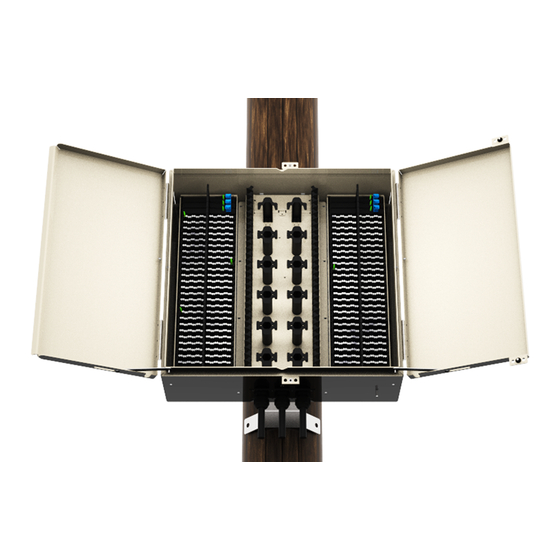
The 864 cabinet configuration with 144 feeder and 864 distribution appearances occupies 42 slots in the cabinet while the remaining 18 slots are used for splitter and parking modules. 432 and 576 cabinet configurations are also available. Figure 1� FDH 5000 Cabinet Page 4 of 24 © 2024 CommScope, Inc. All Rights Reserved... - Page 5 Figure 2� FDH 5000 Cabinet Configurations Page 5 of 24 © 2024 CommScope, Inc. All Rights Reserved...
-
Page 6: All Cabinet Versions
OSP Rollable Ribbon Dielectric or Armored Splitter/Parking slot capacity 18 (864), 30 (576) and 36 (432) Feeder ports Feeder port adapters/connectors LC/APC Feeder Cable Type OSP Rollable Ribbon Dielectric or Armored Page 6 of 24 © 2024 CommScope, Inc. All Rights Reserved... - Page 7 FRONT VIEW VIEW SIDE 36.51 IN FRONT VIEW 35.50 IN VIEW 36.51 IN 35.50 IN TOP VIEW TOP VIEW 21.77 IN 21.77 IN Figure 3� FDH 5000 Cabinet Dimensions Page 7 of 24 © 2024 CommScope, Inc. All Rights Reserved...
-
Page 8: Before Starting The Installation
Open the cabinet door (requires 216B key tool) and check for missing ship-along parts (see installation drawing via QR code) or broken parts. If there are damages, contact CommScope (see Section 18) for an RMA (Return Material Authori- zation) and to reorder if replacement is required. -
Page 9: Cabinet Wall Mount Application
Secure the bottom bracket to the wall using two screws and two flat washers. Tighten each screw securely. Figure 5� Installing Bottom Bracket to Cabinet and Cabinet on wall-Mounted Bracket Page 9 of 24 © 2024 CommScope, Inc. All Rights Reserved... -
Page 10: Cabinet Pole Mount Applications
Danger: Do not stand directly under the cabinet as it is being hoisted into position for mounting. A failure of the lifting equipment could result in serious personal injury. Page 10 of 24 © 2024 CommScope, Inc. All Rights Reserved... -
Page 11: Grounding Wire Connection To Pole Mounted Cabinets
Locate the cabinet grounding lug which is mounted on the underside of the cabinet as shown in Figure 8. Note: The grounding lug may be removed for other approved grounding practices. Figure 8� Grounding Wire Connection To Cabinet Page 11 of 24 © 2024 CommScope, Inc. All Rights Reserved... -
Page 12: Ground Mounting The Cabinet
GROUND SPACER CAPSCREWS (4), LOCK (OPTIONAL ACCESSORY) WASHERS (4), AND FLAT WASHERS (4) FMS COVER ISOLATION GASKET FMS ADAPTER COVER GROUNDING WIRE 23511-A Figure 9� Mounting Cabinet on the FMS Page 12 of 24 © 2024 CommScope, Inc. All Rights Reserved... -
Page 13: Mounting The Cabinet On The Pad Mount
A failure of the lifting equipment could result in serious personal injury. The Pad Mount Frame (PMF), shown in Figure 11, is a stainless steel frame that provides a mounting base for the cabinet when embedded in a concrete foundation. Page 13 of 24 © 2024 CommScope, Inc. All Rights Reserved... -
Page 14: Installation Guidelines
When installed, the top of the conduit should be located 1 to 2 inches (2.54 to 5.08 cm) below the top of the finished concrete pad. Install the conduit before pouring the pad. Figure 12� Constructing the Concrete Pad Page 14 of 24 © 2024 CommScope, Inc. All Rights Reserved... -
Page 15: Concrete Pad Construction
If a ground spacer/riser (accessory) will be installed, place the spacer/riser in position for mounting on the PMF. The isolation gasket installed in step 11.2.4.3 should remain in place between the PMF and spacer/riser. If a spacer/riser will not be installed, proceed to step 11.2.4.7. Page 15 of 24 © 2024 CommScope, Inc. All Rights Reserved... - Page 16 Note: Illustration is for reference only (“Figure 14. Mounting Cabinet on the Concrete Pad”). Figure 14� Mounting Cabinet on the Concrete Pad Figure 15� Removing Side Access Covers From Ground Spacer/Riser Page 16 of 24 © 2024 CommScope, Inc. All Rights Reserved...
-
Page 17: Grounding Wire Connection To Pad Mounted Cabinets
Figure 22 to determine which slot position to pull from. To remove the plastic tray, push the tabs on the right and left side of the slot with your finger and move the tray towards you. The tray will come out completely. Figure 16� Plastic Tray Removal Figure 17� Tabs and Snappers Details Page 17 of 24 © 2024 CommScope, Inc. All Rights Reserved... -
Page 18: Remove The Splitter From Its Original Tray
Align the tray with the designated slot. (Figure 20 shows the order of the installation of the splitters). 12.4.2 Push the tray inward until the tray clicks into place. Figure 20� Order of Splitter Installation Page 18 of 24 © 2024 CommScope, Inc. All Rights Reserved... -
Page 19: Install The Parking Modules
Route the blue pigtail through the edge protectors on the sides and store the remaining slack within the storage area in the center. Figure 22� Connect Feeder Input Pigtail Note: FOR CLARITY ONLY THE INPUT FIBER IS SHOWN. Page 19 of 24 © 2024 CommScope, Inc. All Rights Reserved... -
Page 20: Connect Splitter Output Pigtails
Select the designated distribution port. 15.3 Remove the ferrule dust cap from both connectors of the patch cord and the two selected bulkhead adapters then clean the connectors per local practice. Page 20 of 24 © 2024 CommScope, Inc. All Rights Reserved... -
Page 21: Maintenance And Repair Procedures
Cut replacement lengths of gasket material from the roll as needed. Remove the paper backing to expose the adhesive and then carefully apply the replacement gasket to the door. Take care not to leave any gaps between the meeting sections of the gasket strips. Page 21 of 24 © 2024 CommScope, Inc. All Rights Reserved... -
Page 22: Rear Access To Feeder And Distribution Cables
Move the entire assembly forward and then lifted off the lower studs and away from the cabinet shell. Figure 27� Remove interior 16.3.4 The feeder and distribution cables are now accessible Page 22 of 24 © 2024 CommScope, Inc. All Rights Reserved... -
Page 23: Door Replacement
Transfer all designation information that may be recorded on the damaged door to the labels on the replacement door. 16.4.7 Place the replacement door in position for installation on the hinges. Figure 29� Door Linkage Hardware Page 23 of 24 © 2024 CommScope, Inc. All Rights Reserved... -
Page 24: Screen Vent Service
This product may be covered by one or more U.S. patents or their foreign equivalents. For patents, see www.cs-pat.com. This document is not intended to modify or supplement any specifications or warranties relating to CommScope products or services.
Need help?
Do you have a question about the FDH 5000 432 and is the answer not in the manual?
Questions and answers