Table of Contents
Advertisement
Quick Links
TC-96292-IP
Rev B, September 2020
commscope.com
Contents
Introduction . . . . . . . . . . . . . . . . . . . . . . . . . . . . . . . . . . . .1
Related Publications . . . . . . . . . . . . . . . . . . . . . . . . . . . . .1
1
Product Description . . . . . . . . . . . . . . . . . . . . . . . .2
1.1
General Description. . . . . . . . . . . . . . . . . . . . . . . .2
1.2
Dimensions and Specifications . . . . . . . . . . . . . . .4
2
Unpacking and Inspection . . . . . . . . . . . . . . . . . . .5
3
Installation . . . . . . . . . . . . . . . . . . . . . . . . . . . . . . .6
3.1
General . . . . . . . . . . . . . . . . . . . . . . . . . . . . . . . . .6
3.2
Overview of Installation . . . . . . . . . . . . . . . . . . . . .6
3.3
Required Tools and Material . . . . . . . . . . . . . . . . .7
3.4
Footprint and Installation Template . . . . . . . . . . . .7
3.5
Mounting the Frame on a Concrete Floor . . . . . . .8
3.6
Mounting the Frame on a Raised Floor. . . . . . . .13
3.7
3.8
3.9
Grounding Frame, Installing Gang Plates . . . . . .18
4
Installing an Optional Splice Cabinet. . . . . . . . . .21
5
Contact Information . . . . . . . . . . . . . . . . . . . . . . .22
Introduction
This user manual describes the Flex Frame
and provides directions for installation. Proce-
dures include: unpacking the frame, mounting
the frame on concrete floor, mounting the frame
on a raised floor, installing the aftermarket rack
numbering labels, installing cable manager and
accessories, and grounding the frame and
installing gang plates (in lineup). This user
manual lists related publications and tells how
to obtain technical assistance.
Related Publications
The following related publications are available at
•
Flex Frame Cable Clamping Application Guide (TC-96289-IP) -- provides guidelines
for using the flex frame with factory pre-terminated fiber termination panels and Com-
mscope cable clamp bracket kits (included with frame) or cable clamp kits (sold sepa-
rately)
•
Flex Frame Universal Splice Cabinet User Manual (TC-96291-IP) -- provides guide-
lines for installing the Flex Frame Universal Splice Cabinet when purchased separately
from the Flex Frame.
860658953
Rev A
Flex Frame
https://www.commscope.com/SupportCenter
User
Manual
Flex Frame
Page 1 of 22
© 2020 CommScope, Inc.
Advertisement
Table of Contents

Related Manuals for CommScope ODF-FF19CM-40RU


Summary of Contents for CommScope ODF-FF19CM-40RU
-
Page 1: Table Of Contents
• Flex Frame Universal Splice Cabinet User Manual (TC-96291-IP) -- provides guide- lines for installing the Flex Frame Universal Splice Cabinet when purchased separately from the Flex Frame. 860658953 Page 1 of 22 © 2020 CommScope, Inc. Rev A... -
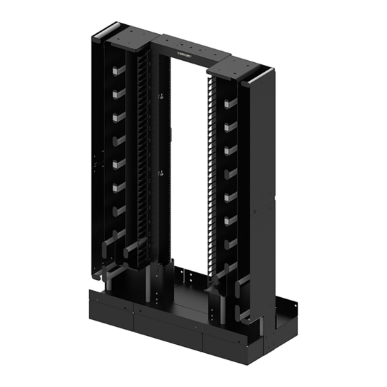
Page 2: Product Description
The basic product consists of a 19-inch seismic rack with two cable managers, one on each side. Two sizes are offered: ODF-FF19CM-40RU, which has 40 rack units of connector panel spacing, and ODF-FF19CM-36RU, which has 36 rack units. - Page 3 Rear Trough -- is used to route patch cords horizontally on rear bottom of frame. FLAT CLAMP BRACKET OFFSET CLAMP BRACKET ACCESSORY RAIL (2X) REAR TROUGH 27210-A Figure 2. Flex Frame (Rear Isometric View) Page 3 of 22 © 2020 CommScope, Inc. .
-
Page 4: Dimensions And Specifications
Flex Frame. Table 1: Flex Frame Installation Specifications Parameter Specification Catalog numbers ODF-FF19CM-36RU (760242401) 36 RU frame alone; ODF-FF19CM-36RU-SP (760242402) 36RU with splice cabinet; ODF-FF19CM-40RU (760249125) 40 RU frame alone Page 4 of 22. © 2020 CommScope, Inc. -
Page 5: Unpacking And Inspection
Inspect the exterior of the shipping container(s) for evidence of rough handling that may have damaged the components in the wood crate. If damage is detected or if parts are missing, file a claim with the commercial carrier and notify CommScope Support Center http://www.commscope.com/SupportCenter The crate is held together with 36 TORX size T7 wood screws. -
Page 6: Installation
Frame is grounded and gang plates are added for frames in a lineup. • Splice cabinet is installed (optional). • The total assembly is final checked to ensure everything is in correct order. Page 6 of 22. © 2020 CommScope, Inc. -
Page 7: Required Tools And Material
Flex Frame installation template with dimensions of footprint, 14.0 IN. 24.0 IN. (35.6 CM) (61.0 CM) 3.9 IN. 18.75 IN. (9.9 CM) (47.63 CM) 52.8 IN. (134.0 CM) 27223-A Figure 5. Frame Footprint (Optional Template Shown) Page 7 of 22 © 2020 CommScope, Inc. . -
Page 8: Mounting The Frame On A Concrete Floor
Figure 6. Mark the location with the installation template, as shown. FRONT AISLE (4-FEET REAR AISLE RECOMMENDED (3-FEET MINIMUM) RECOMMENDED MINIMUM) CONCRETE FLOOR 27251-A Figure 6. Determining Frame Location Page 8 of 22. © 2020 CommScope, Inc. - Page 9 3. Set aside the isolation pad and drill four mounting holes in the concrete at the marks just made, as shown in Figure DRILL VACUUM AS REQUIRED HOLE DIMENSIONS: DIAMETER: 0.71-IN. (18mm) DEPTH: 3-15/16-IN. (100mm) 27238-A Figure 8. Drilling Mounting Holes Page 9 of 22 © 2020 CommScope, Inc. .
- Page 10 TORQUE NUT WASHER THREADED ROD ANCHOR SLEEVE ANCHOR BOLT ASSEMBLED TAP ANCHOR BOLT WITH HAMMER WASHER TOUCHES CONCRETE 24992-A SIDE VIEW Figure 9. Installing Washer and Torque Nut on Threaded Rod Page 10 of 22. © 2020 CommScope, Inc.
- Page 11 TC-96292-IP 5. Pre-torque the anchor bolt to approximately 30 foot-pounds (41 Newton meters). Refer to Figure FT-LB 24993-A TORQUE WRENCH Figure 10. Pre-torquing Anchor Bolt Page 11 of 22 © 2020 CommScope, Inc. .
- Page 12 6. Loosen the torque nuts several turns, and then remove the torque nut and washer, as shown in Figure LOOSEN TORQUE NUT 24994-A TORQUE NUT WASHER REMOVE TORQUE NUT AND WASHER THREADED ROD Figure 11. Removing Torque Nut and Washer Page 12 of 22. © 2020 CommScope, Inc.
-
Page 13: Mounting The Frame On A Raised Floor
TC-96292-IP 3.6 Mounting the Frame on a Raised Floor The Flex Frame can be mounted on a raised floor using the CommScope Raised Floor Mounting Kit, 5/8” (FDF-ACC146). Figure 15 shows an exploded view of the kit components. To order the kit, refer to the following URL: https://www.commscope.com/product-type/cabinets-panels-enclosures/frames-racks-cabinets/... -
Page 14: Installing Aftermarket Rack Numbering Labels
RU number 1. Repeat this procedure for the remaining rack rails. For the 40 RU Flex Frame (ODF-FF19CM-40RU) – locate the four rolls of adhesive RU labeling tape and carefully cut off and discard the RUs numbered from 41-52 from each tape. Beginning at the uppermost rack unit on the rack, begin applying the label tape over the silk-screened Page 14 of 22. -
Page 15: Installing Cable Managers And Accessories
RIGHT CABLE MANAGER BOLT (6X EACH SIDE) WASHER (6X EACH SIDE) WASHER (6X EACH SIDE) SPLIT LOCK WASHER (6X EACH SIDE) (6X EACH SIDE) 27252-A Figure 15. Installing the Cable Managers Page 15 of 22 © 2020 CommScope, Inc. . - Page 16 LEFT CABLE MANAGER RIGHT CABLE MANAGER REAR BOTTOM CENTER #12-24 SCREW SHELF (4X EACH SHELF) 27258-A FRONT #12-24 BOTTOM STAR WASHER CENTER (4X EACH SHELF SHELF) Figure 16. Installing the Middle Shelves Page 16 of 22. © 2020 CommScope, Inc.
- Page 17 For mounting location of clamp brackets, see Figure 2 on Page ACCESSORY RAILS RACK PASS THRU RADIUS LIMITERS (FASTEN TO RACK FRONT AND REAR) #12-24 SCREWS 27214-A AND LOCK WASHERS Figure 17. Installing Pass Thru Radius Limiters Page 17 of 22 © 2020 CommScope, Inc. .
-
Page 18: Grounding Frame, Installing Gang Plates
Assemble as shown, using #12-24 screws. Note: For an exploded view of a gang plate installation, see Figure 20 on Page Page 18 of 22. © 2020 CommScope, Inc. - Page 19 GROUND STRAP STRAP FRONT VIEW 14.0 IN. (35.6 CM) 18.75 IN. (47.63 CM) 34.0 IN. (86.3 CM) 18.75 IN. (47.63 CM) 27248-A TOP VIEW Figure 19. Two Frames in a Lineup Page 19 of 22 © 2020 CommScope, Inc. .
- Page 20 TC-96292-IP 27229-A GROUNDING STRAP GANG PLATE #12-24 SCREWS AND LOCK WASHERS Figure 20. Installing Gang Plates and Grounding Straps in Flex Frame Lineup Page 20 of 22. © 2020 CommScope, Inc.
-
Page 21: Installing An Optional Splice Cabinet
Hang the splice cabinet on the screws just installed and fasten the cabinet using #12-24 screws. Refer to Figure 21 and also to Figure 22 on Page Page 21 of 22 © 2020 CommScope, Inc. . -
Page 22: Contact Information
27218-A Figure 22. Installing the Splice Cabinet Contact Information ® • To find out more about CommScope products, visit us on the web at www.commscope.com • For technical assistance, customer service, or to report any missing/damaged parts, visit us at http://www.commscope.com/SupportCenter...
Need help?
Do you have a question about the ODF-FF19CM-40RU and is the answer not in the manual?
Questions and answers