
Related Manuals for Atlanta Attachment Company 1309B


Summary of Contents for Atlanta Attachment Company 1309B
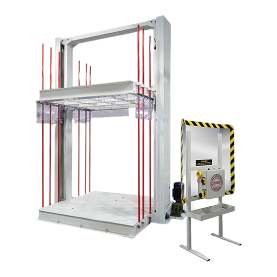
- Page 1 1309B Model Spring Unbaler Revision 1 Updated February 07, 2023 Technical Manual & Parts Lists Atlanta Attachment Company 362 Industrial Park Drive Lawrenceville, GA 30046 770-963-7369 • www.atlatt.com...
- Page 3 Attachment Company. In addition to any confidentiality and non-disclosure obligations that currently exist between you and Atlanta Attachment Company, your use of these materials serves as an acknowledgment of the confidential and proprietary nature of these materials and your duty not to make any unauthorized use or disclosure of these materials.
-
Page 4: Table Of Contents
Technical Manual & Parts Lists Contents Important Safety Instruction ........................0 Mandatory Information ..........................0 Scope of the Instruction Material ........................ 0 Intended Use ............................... 0 Exclusion of Misuse ............................ 0 Liability ............................... 1 Choice and Qualification of Personnel ....................... 1 Training ............................... - Page 5 11309B Main Assembly ........................... 36 1309092 Motor Assembly........................43 1309309 Operator Station Assembly ....................44 1309088 Control Panel Assembly ......................45 1309087 Electrical Panel ........................47 1335M-116 Foot Pedal Assembly ......................49 1309A-WD Wiring Diagram ........................ 50 1309B-WD Electrical Diagram......................51...
-
Page 6: Important Safety Instruction
Important Safety Instruction This part of the Instruction Material is provided for the safe use of your equipment. It contains important information to help work safely with the unit and describes the dangers inherent in machinery. Some of these dangers are obvious, while others are less evident. -
Page 7: Liability
Technical Manual & Parts Lists Liability The machine should only be operated when in perfect working order, with due regard for safety and the potential dangers, as well as in accordance with the Instruction Material. Faults and malfunctions capable of impairing safety should be remedied immediately. -
Page 8: A Word To The Operator
Technical Manual & Parts Lists A Word to the Operator The greatest danger inherent in our machines: is that of fingers, hands or loose clothing being drawn into a machine by live, coasting or rotating tools or assemblies or of being cut by sharp tools or burned by hot elements. LWAYS BE CONSCIOUS OF THESE DANGERS Safety Equipment on the Machines All machines are delivered with safety equipment, which shall not be removed or... -
Page 9: Protective Eyewear
Technical Manual & Parts Lists Protective Eyewear Protective eyewear that has been tested by the local authorities should be worn whenever there is a possibility of loose or flying objects or particles such as when cleaning the machine with compressed air. Tools Always count the number of tools in your possession before starting work on the machine. -
Page 10: Important Notices
Technical Manual & Parts Lists Important Notices Reporting and Fighting Fires Read the instructions posted in the factory about reporting fires and the emergency exits. Make sure you know exactly where the fire extinguishers and sprinkler systems are located and how they are operated. Pass on the corresponding information to the firemen when they arrive. -
Page 11: Delivery Of The Machine/Packaging
Technical Manual & Parts Lists - Kinetic energy - Note that some motors or spindles, for example, may continue to run or coast run on after being switched off. - Potential energy - Individual assemblies may need to be secured if necessary for repair work. Delivery of the Machine/Packaging Note any markings on the packaging, such as weights, lifting points and special information. -
Page 12: Workplace Environment
Technical Manual & Parts Lists Workplace Environment Our machines are designed for use in enclosed rooms: Permissible ambient temperature approx. 5 - 40 °C (40 - 104 °F). Malfunctions of the control systems and uncontrolled machine movements may occur at temperatures outside this range. -
Page 13: Repair
Technical Manual & Parts Lists When scrapping (disassembling) the machine and its assemblies, ensure that these materials are disposed of safely. Either commission a specialist company familiar with the local regulations or note the local regulations when disposing of these materials yourself. Materials should be sorted properly. Repair Replacement Parts We cannot accept any liability whatsoever for damage due to the use of parts made by other manufacturers... -
Page 14: General Liability
Technical Manual & Parts Lists General Liability Liability for machine damage and personal injury is extinguished completely if any unauthorized conversions or modifications are undertaken. The machine must not be modified, enlarged, or converted in any way capable of affecting safety without the manufacturer's prior approval. Starting Machine Movements Read the Instruction Manual carefully to establish which keys and functions start machine movements. -
Page 15: Safety Precautions
Technical Manual & Parts Lists Safety Precautions Safety should be a constant concern for everyone. Always be careful when working with this equipment. While normal safety precautions were taken in the design and manufacture of this equipment, there are some potential safety hazards. -
Page 16: General Machine Data
Technical Manual & Parts Lists General Machine Data Specifications Electrical Requirements: 220 VAC, 3 Phase, 50/60 Hz, 15 amp Main Motor Power: 5 hp Max Load: 22,000 ft.-lbf (99kN) L 131” x W 87” x H 152” Overall Dimensions: L 3330mm x W 2210mm x H 3860mm Max Unbaling Quantity: 20 pcs Power Supply:... -
Page 17: 1309 Foot Print
Technical Manual & Parts Lists 1309 Foot Print... -
Page 18: Installation Instructions
Technical Manual & Parts Lists Installation Instructions Installation should be performed by a qualified mechanic. Step 1: Place the lower platform on a flat, level area of the floor. Ensure there is enough room around the machine for spring loading and discharge. SSSCM20X65 WWLM20 WWFM20... - Page 19 Technical Manual & Parts Lists SSSCM12X25 WWLM12 WWFM12 Step 3: Install the Top Support Beam to the Side Beams. The screws should be torqued to 70 lbf ft. SSSCM12X35 WWLM12 WWFM12 Step 4: Insert the Drive Shaft thru the hole in the Bottom Platform. Install the gears on both ends. The screws should be torqued to 70 lbf ft.
- Page 20 Technical Manual & Parts Lists SSCM10X35 WWLM10 WWFM10 SSSCM12X50 WWLM12 WWFM12 NNHM12X1.75 WWLM12 WWFM12 Step 5: Mount the Lead Screw assembly to the Side Beam by inserting the top end thru the hole in the Top Support Beam and fastening the (4) 12mm screws thru the bearing at the lower end of the Lead Screw assembly to the tapped holes in the Side Beams.
- Page 21 Technical Manual & Parts Lists SSCM10X75 WWLM10 WWFM10 Bearing Flange Plate Rubber Cushion Bearing Mount NNEM10-1.5 WWFM10 Step 6: Install the bearing mounts, rubber cushions and the bearing flange plates on both sides. IMPORTANT! The screws (SSSCM10X75) should tighten just until the lock washers (WWLM10) are fully compressed.
- Page 22 Technical Manual & Parts Lists Step 7: Loosen the 4 mounting screws on the lower end of the Lead Screw assembly. Using a crowbar, lift the Lead Screw assembly until there is approx. .020” gap between gear teeth. The beveled surfaces of the two gears should be flush as shown below.
- Page 23 Technical Manual & Parts Lists Step 8: Using the M16 X 220MM screws provided, fasten the Side Plate to the top platform. Repeat this on the other side of the machine. The screws should be torqued to 110 lbf ft.
- Page 24 Technical Manual & Parts Lists Step 9: Insert Shoulder Bolt (1) thru the top left slot in the Side Plate (2). Insert the Roller (3) and Spacer (4) on the Shoulder Bolt as shown above. Repeat this using the lower left slot in the Side Plate. Step 10: Insert Shoulder Bolt (1) thru the top right slot in the Side Plate (2).
- Page 25 Technical Manual & Parts Lists Step 11: Check oil level in gear box. Use 85-90w gear oil. Install the motor to the motor mount plate as shown. Use the slots to adjust the tension of the drive chain. The 12mm screws should be torqued to 105 lbf ft.
- Page 26 Technical Manual & Parts Lists Step 13: Secure the Upper Limit Switches using the bolts provided to the tapped holes in the side beam on the motor side. Step 14: Insert the (8) poles thru the guide rings in the top platform. Use the supplied bolts (1/4-20 x 2-3/4”) and lock nuts to secure the poles to the guide ring in the lower platform.
- Page 27 Technical Manual & Parts Lists Step 15: Using the brackets and hardware provided, install the vinyl guards as shown above.
- Page 28 Technical Manual & Parts Lists Step 16: Install the gear guard on the side opposite of the motor as shown above. Step 17: Install the top roller guards and bottom roller guards on both sides of the machine as shown above.
- Page 29 Technical Manual & Parts Lists Step 18: Install the side guards on both sides of the machine as shown above. Step 19: Install the chain guard.
- Page 30 Technical Manual & Parts Lists Step 20: Install the tall screw guard’s assemblies on both sides of the machine.
- Page 31 Technical Manual & Parts Lists Step 21: Position the Control Unit and connect the motor according to the wiring diagram on 45.
- Page 32 Technical Manual & Parts Lists Step 22: Connect the main power. This machine requires 220 VAC, Three Phase, 50/60 Hz, 16 amp, 3700 watts. Step 23: Turn the machine on. Step 24: Using the control panel, lower the upper platform until it measures 6 inches from the lower platform on the opposite side of the motor.
-
Page 33: Leveling The Upper Platform Side To Side
Technical Manual & Parts Lists Leveling the Upper Platform Side to Side Important : You must disconnect the power to the machine before making this adjustment. 1.) Loosen the 4 bolts in the slots which secure the motor to the motor mount plate. 2.) Remove the chain from the motor sprocket. - Page 34 Technical Manual & Parts Lists 4.) Loosen the set screw in the collar behind the drive shaft bearing. 5.) Using a pulley puller, remove the drive shaft bearing and collar. 6.) Loosen the screw in the driven sprocket. 7.) Using a pulley puller, pull the sprocket approx. 1” towards the end of the shaft. 8.) Loosen the screw in the beveled gear.
- Page 35 Technical Manual & Parts Lists 9.) Using a pulley puller, pull the gear until it is no longer meshed with the mating gear. 10.) Turn the Lead Screw assembly until the upper and lower platforms are parallel. - Clockwise lowers the motor side of the upper platform. - Counter clockwise raises the motor side of the upper platform.
-
Page 36: Leveling The Upper Platform Front To Back
Technical Manual & Parts Lists Leveling the Upper Platform Front to Back Measure the distance between the upper and lower platforms on both the front and back of the machine. If these two measurements are the same, the platform is level from front to back. If the measurements are not the same, use the adjustment screws (shown below) to tilt the upper platform until it is level. -
Page 37: Solving Binding Issues
Technical Manual & Parts Lists Solving Binding Issues If the two Lead Screw assemblies are not parallel the machine may bind when the upper platform is being raised or lowered. Use the following instructions below to relieve any binding. 1.) First, verify that the distance between the upper and lower platforms is the same on both sides. Refer to “Leveling the Upper Platform Side To Side”... - Page 38 Technical Manual & Parts Lists Warning! Disconnect the power source before inserting shim. 6.) After the shims have been inserted, reconnect the power source. Repeat steps 3 thru 6. Thicker shims may be required if binding still occurs. After shims have been installed and binding no longer occurs, turn the “Current” dial back to the “10 o’clock”...
-
Page 39: Operating Instructions
Technical Manual & Parts Lists Operating Instructions Before each shift, lubricate all gears, the chain and the two Lead Screws. The Lead Screws require special lubrication. Use Acme Screw Grease (NLU-2001). 1.) Turn the Main Power switch to the on position. 2.) Turn the “Direction Selector”... -
Page 40: Machine Maintenance
Technical Manual & Parts Lists Machine Maintenance Maintenance should only be performed by trained, qualified personnel. Before performing any maintenance or repair work, switch off the electrical, pneumatic, etc. power to the machine at the main source and secure it with a padlock so that it cannot be switched on again without authorization. Always wear proper safety equipment when operating or performing maintenance on any equipment. -
Page 41: Assembly Drawings & Parts Lists
Technical Manual & Parts Lists Assembly Drawings & Parts Lists The materials contained herein are confidential and proprietary information of Atlanta Attachment Company. In addition to any confidentiality and non-disclosure obligations that currently exist between you and Atlanta Attachment Company, your use of these materials serves as an acknowledgment of the confidential and proprietary nature of these materials and your duty not to make any unauthorized use or disclosure of these materials. -
Page 42: 11309B Main Assembly
Technical Manual & Parts Lists 11309B Main Assembly AAC Drawing Number 9005816 Rev 0 Main Assembly Complete view... - Page 43 Technical Manual & Parts Lists Exploded main view left side...
- Page 44 Technical Manual & Parts Lists Exploded main view middle...
- Page 45 Technical Manual & Parts Lists Exploded main view right side...
- Page 46 Technical Manual & Parts Lists 1309B parts list...
- Page 47 Technical Manual & Parts Lists 1309B parts list continued...
- Page 48 Technical Manual & Parts Lists 11309 parts list continued...
-
Page 49: 1309092 Motor Assembly
Technical Manual & Parts Lists 1309092 Motor Assembly AAC Drawing Number 1309092 Rev 2... -
Page 50: 1309309 Operator Station Assembly
Technical Manual & Parts Lists 1309309 Operator Station Assembly AAC Drawing Number 1309309 Rev 3... -
Page 51: 1309088 Control Panel Assembly
Technical Manual & Parts Lists 1309088 Control Panel Assembly AAC Drawing Number 1309088 Rev 3... - Page 52 Technical Manual & Parts Lists 1309088 parts list...
-
Page 53: 1309087 Electrical Panel
Technical Manual & Parts Lists 1309087 Electrical Panel AAC Drawing 1309087 Rev 4... - Page 54 Technical Manual & Parts Lists 1309087 parts list...
-
Page 55: 1335M-116 Foot Pedal Assembly
Technical Manual & Parts Lists 1335M-116 Foot Pedal Assembly AAC Drawing Number 9003047 Rev 2... -
Page 56: 1309A-Wd Wiring Diagram
Technical Manual & Parts Lists 1309A-WD Wiring Diagram AAC Drawing Number 125012D Rev 2... -
Page 57: 1309B-Wd Electrical Diagram
Technical Manual & Parts Lists 1309B-WD Electrical Diagram AAC Drawing Number 125874D Rev 3... - Page 58 (800) hours of operation or one hundred (100) days whichever comes first. Atlanta Attachment Company warrants all electrical components of the Serial Bus System to be free from defects in material or workmanship for a period of thirty-six (36) months.
- Page 59 Declaración de Garantía Productos Manufacturados Atlanta Attachment Company garantiza que los productos de fabricación son libres de defectos de material y de mano de obra durante un periodo de ochocientos (800) horas de operación o cien (100) días cual llegue primero. Atlanta Attachment Company garantiza que todos los componentes del Serial bus son libres de defectos de material y de mano de obra durante un periodo de treinta y seis (36) meses.
Need help?
Do you have a question about the 1309B and is the answer not in the manual?
Questions and answers