
Related Manuals for Atlanta Attachment Company 1306F


Summary of Contents for Atlanta Attachment Company 1306F
- Page 1 1306F Model Preliminary Copy Rev.0 November 28, 2023(wr) Technical Manual & Parts Lists Atlanta Attachment Company 362 Industrial Park Drive Lawrenceville, GA 30046 770-963-7369 • www.atlatt.com...
- Page 2 The materials contained herein are confidential and proprietary information of Atlanta Attachment Company. In addition to any confidentiality and non-disclosure obligations that currently exist between you and Atlanta Attachment Company, your use of these materials serves as an acknowledgment of the confidential and proprietary nature of these materials and your duty not to make any unauthorized use or disclosure of these materials.
-
Page 3: Table Of Contents
Contents CONFIDENTIAL AND PROPRIETARY INFORMATION ............0 SAFETY INSTRUCTION ......................3 Important Notices............................6 Maintenance ..............................8 INSTALLATION ......................... 11 ........................11 ARTS AND OMPONENTS ..........................12 TILITY OOKUPS ........................13 ACHINE PECIFICATIONS Power Requirements ........................13 Physical Specs: ..........................13 Mattress Size Limitations: ...................... - Page 4 Available Menus ..........................41 1306F – Main Screen ........................41 Ready to Load Screen........................42 Advanced Functions ........................42 Style Editing ........................... 43 Detailed Method............................43 Shortest Method ............................47 2.4.......................... 49 AINTENANCE General Safety Instructions ......................49 Daily ...............................
- Page 5 IRCUIT 1306D-PD P ....................... 151 NEUMATIC IAGRAM 1306-PD3 P ......................152 NEUMATIC IAGRAM TRAINING ........................153 ATLANTA ATTACHMENT COMPANY (AAC) STATEMENT OF WARRANTY ..... 154 ......................154 ANUFACTURED RODUCTS : ........................154 ERMS AND ONDITIONS ..........................154 OVERED ........................154 OVERED DECLARACIÓN DE GARANTIA ....................
-
Page 6: Safety Instruction
Safety Instruction This part of the Instruction Material is provided for the safe use of your equipment. It contains important information to help work safely with the unit and describes the dangers inherent in machinery. Some of these dangers are obvious, while others are less evident. - Page 7 The personnel's awareness of the dangers and compliance with the safety regulations should be checked at irregular intervals. Choice and Qualification of Personnel Ensure that work on the machine is only carried out by reliable persons who have been appropriately trained for such work - either within the company, by our field staff or at our office - and who have not only been duly appointed and authorized but are also fully familiar with the local regulations.
- Page 8 shift. Damage found shall be immediately remedied by a duly authorized person before resuming operation of machine. The machine should only be operated when in perfect working order and when all protective mechanisms and safety equipment, such as detachable protective mechanisms, emergency STOP systems, etc.
-
Page 9: Important Notices
Important Notices Reporting and Fighting Fires Read the instructions posted in your factory about reporting fires and the emergency exits. Make sure you know exactly where the fire extinguishers and sprinkler systems are located and how they are operated. Pass on the corresponding information to the firemen when they arrive. Ensure there are enough signs to avoid fire hazards. - Page 10 The packaging and machine must immediately be examined for signs of damage in transit. Such damage must be reported to the shipper/transporter within the applicable time limits. Contact Atlanta Attachment Company and/or your transport insurer immediately, if signs of damage are visible. Never operate a damaged machine.
-
Page 11: Maintenance
Local Regulations Particular attention must be paid to local and statutory regulations, etc. when installing machines and the plant (e.g. with regard to the specified escape routes). Note the safety zones in relation to adjacent machines. Maintenance General Safety Instructions The machine shall be switched off, come to a standstill, and be secured so that it cannot be switched on again inadvertently before starting any maintenance work whatsoever. - Page 12 Repair, Electrical The power supply must be switched off (master switch off) and secured so that it cannot be switched on again inadvertently before starting any work on live parts. Those parts of the machine and plant on which inspection, maintenance or repair work is to be carried out must be isolated from the power supply, if specified.
- Page 13 Safety Precautions Safety should be a constant concern for everyone. Always be careful when working with this equipment. While normal safety precautions were taken in the design and manufacture of this equipment, there are some potential safety hazards. Everyone involved with the operation and maintenance of this equipment should read and follow the instructions in this manual.
-
Page 14: Installation
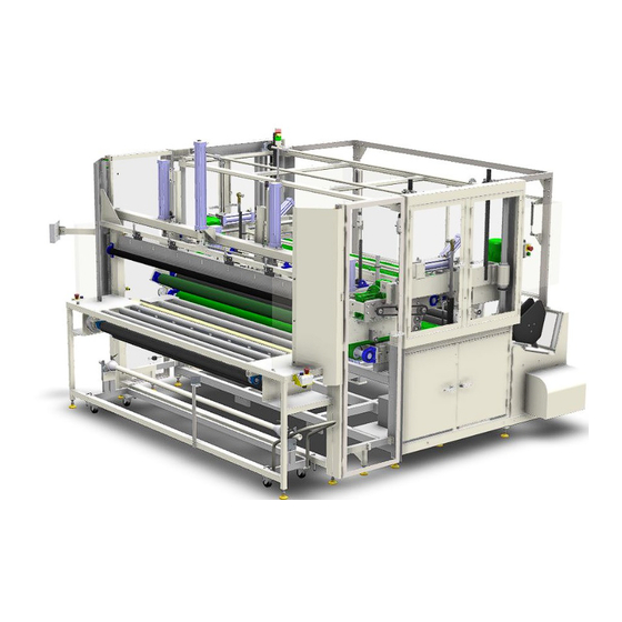
INSTALLATION It is important that the machine operator read this manual and is familiar with all the functions and safety concerns of the unit before Installing and operating. Parts and Components Fig 1 Left door Roll Storage cart Infeed unit Right Door Main Unit... -
Page 15: Utility Hookups
Utility Hookups Top View of 1306F Electrical drop = 208v-240v 50hz/60hz 50amp circuit Air drop = 100 psi dried shop air. 3/8-inch line minimum. -
Page 16: Machine Specifications
Machine Specifications Capacity & Production Specs. Production / Through Put 1 -2 pieces per minute 86” wide Max Width of Mattress Max Height under Pressure Roller: 15” wide 1 roll (12” diameter) Roll capacity, bottom 92” Film width: Bottom (inch) Power Requirements Volts 208V-240V -- 3-phase 50/60 Hz... -
Page 17: Options
Options • 11307SA Auto Secondary Roll Pack • 13061395 Raised Mattress Boxing Table • 1306141 - Plastic Roll Carriage • LSC2005 Conveyor System • Extended Loading Table Use in case of no Conveyor System • Pre-fold System Use in conjunction with Auto-Pac™ (1390) with Compression Module... -
Page 18: Set Up
Set Up • Remove any shipping straps from machine. • Inspect the machine for any damage that may have occurred during shipping. If damage is found, report this immediately to your supervisor. Document the damage and provide details and photographs. •... -
Page 19: Machine Layout
Machine Layout A. In-feed Unit C. Main unit 1. Roll Storage Cart. 10. Upper Pressing Platform 2. Plastic Hold Down Bar. 11. Rear Cross Seal 3. Heated Cut Bar. B. Machine Controls D. Output Carriage unit 4. Touch Screen 5. Infeed E-Stop and Power Switch. 6. -
Page 20: Machine Safety
Machine Safety The 1306 model roll pack workstation has many powerful drives and mechanisms. ANYONE assigned to operate and/or maintain this machine must be properly trained by an Atlanta Attachment Technician, or a trained and qualified factory mechanic. Operation and/or maintenance of this machine by untrained personnel may result in a serious injury or even death. -
Page 21: Warning 1
Warning 1 The machine makes automatic movements at the beginning of power up that could pinch, crush, or kill a person inside the machine. Also never allow anyone in or on the machine when powering up. In auto mode this machine can start automatically once the In-feed sensor is covered. If the In-feed sensor should fail, in auto mode the machine could start moving without a bed being feed into the machine. -
Page 22: 1.1. Lockout/Tagout Program
The following references provide information about the LOTO process. Equipment Energy Control Procedure Lockout/Tagout Program Description: Roll Pack Workstation Model: 1306F Locatio Manufacturer: Atlanta Attachment Co. Energy Location Magnitude Control Method... -
Page 23: Operation
OPERATION It is important that the machine operator read this manual and is familiar with all the functions and safety concerns of the unit before operating. Individual Components A. Control Panel The Control Panel allows the operator to start and stop the automatic function of the machine, shut off power to the machine in the event of an emergency. -
Page 24: 2.1. Machine Set-Up
2.1. Machine Set-up Film Loading. The Standard machine comes with a pull-out film roll cart that can handle a 12” diameter x 92” long roll of plastic. The film cart can be loaded two ways. It can be inserted from the left or the right of the machine for loading. - Page 25 9. Route plastic as shown in diagram. Load Plastic until it reaches the cut bar location and hold preventing it from slipping off infeed, 10. Refer to Ready Screen and press Operator Functions Button for access to Film Cut/Load Button as shown below Push Button “Film Cut / Load Cycle to manually active this function to clamp plastic.
-
Page 26: Machine Screens
Machine Screens. The Styles Select Screen is accessed from the Ready Screen. Styles Accessed on Setup Screen. Settings for different bed thicknesses and types can be accessed, viewed, and saved. (Mechanic or higher level) Show all styles Advanced Styles, pages 1, 2 and 3 Push Style Select Menu to Select Styles Push Style Edit Menu or Keypad to Edit Styles Caution: Default Style will return “all”... -
Page 28: Advanced Settings
Advanced Settings (Mechanic or higher level) Style Only Settings Pages 1 - 2 Machine Only Settings Pages 3, 4 and 5... -
Page 29: Resetting Piece Count
Resetting Piece Count System Information Accessed on the Setup Screen(Mechanic or higher level) Security Information Accessed on Setup Screen Factory Default is set to Operator Level... -
Page 30: Seal Bar Temperature Settings
Seal Bar Temperature Settings Accessed by Advance Settings Page 3 (Mechanic or higher level) Show All Settings Page Maintain a copy for backup and future reference Advanced Manual Information Accessed on Setup Screen (Mechanic or higher level) - Page 31 Advanced Manual Continued...
-
Page 32: Compensation
Compensation: Packing Height and Main Belt Buttons Pneumatic Cycle Manually cycle all pneumatic components (Mechanic or higher level) -
Page 33: Vfd Drive Setup
VFD Drive Setup Accessed on Setup Screen (Mechanic or higher level) - Page 34 VFD Drives Continued...
-
Page 35: Run Modes
Run Modes Accessed on Setup Page(Mechanic or higher level) Manual Mode Use only to manually step through the rolling process Automatic Modes Mode 1 -4: used to preset all processes for styles Pass Thru Mode: Allows product pass through without rolling up Unload Direction: Allows left or right unloading... -
Page 36: Machine Sequence
Machine Sequence Pressing the start button on the Ready Page will put the machine in automatic mode. Understanding the effects of the settings. (Cont’d) Step 1. The press platform lowers to the lower limit and resets the press position counter then rises to the Packing Height Load Distance setting. - Page 37 Step 3. The mattress is pushed into the conveyor belts and the conveyors draw the mattress towards the rolling chamber. The mattress is released by the operator at this time. Step 4. The Pressing start sensor is blocked and pressing belt is lowered to the Air Regulator Pressing Conveyor setting.
- Page 38 Step 5. The conveyor begins to feed the compressed mattress into the rolling chamber. As the roll becomes more compressed, the platform shifts to the left to maintain the Air Regulator Compression setting Step 6. The conveyor continues to feed the compressed mattress into the rolling chamber. Pack Position Distance 1(Advanced Settings) is met and the pressing platform indexes to the Packing Height Distance 2 position.
- Page 39 Step 7. The feed start sensor is unblocked and the machine resets the cut bar distance counter. The machine begins counting the Cut Bar Distance setting. Step 8. the Pack Position Distance 2(Advanced Settings) position is met, and the platform moves to the Packing Height Distance 3 position.
- Page 40 Step 9. The Cut Bar Distance setting is met, and the cut bar and plastic gripper descend to cut the final wrap of plastic used to roll the mattress. The seal bar position counter is reset, and the Seal Bar Position Distance setting begins to be counted. Step 10.
- Page 41 Step 11. The platform moves to the platform upper limit position and lowers the turn baffle to eject the mattress roll. Step 12. If the unload sensor has not been met, then the ejector finger fire to eject the roll from the turn baffle.
-
Page 42: 2.2. Machine Operation
2.2. Machine Operation Machine Start Up 1. Turn main power disconnect switch to ON position. 2. Turn Main Air Valve to the ON position. The pressure on the gauge should be set to 90 PSI. 3. Ensure all E-Stops are disengaged on all 4 corners of the machine. 4. -
Page 43: General Instructions
General Instructions It is important that the machine operator read this manual and is familiar with all the functions and safety concerns of the unit before operating. 2.3. General Operation ATTENTION: DO NOT USE ANY SHARP OBJECTS TO TOUCH THE SCREEN The graphics images presented on the touch screen show "3-dimensional"... -
Page 44: Available Menus
Available Menus The following is a summary of functions available for the Machine Operator. 1306F – Main Screen The normal operation of the machine is controlled from the main 1306FF – READY screen. From here you can start the automatic cycle and access all machine functions. -
Page 45: Ready To Load Screen
Ready to Load Screen. Operator can begin automatic rolling from this screen. Accessed by pressing start from the main screen while machine is up to temperature. FILM LOAD CYCLE: This button actuates the plastic gripper bar to lower and grab the wrapping plastic. NOTE: Be sure hazard tapped area of in-feed table surface is clear of foreign objects and/or body parts before pressing this button. -
Page 46: Style Editing
Style Editing Detailed Method With Descriptions of each Setting(Mechanic or higher level) Press Setup Button on Ready/Home screen Press Advanced Styles Button Press Right Arrow Button for Page 2 or 3 Locate & Press Setting# for change... - Page 47 Press left or right arrow button to access # 1 -18 settings for Position, Height, Seal and Cut Press the top of the button for explanation of settings and + / - to change number value...
- Page 48 Final Pack Heigh(1) Cut Bar Position(2) Seal Bar Position(3) Air Regulator, Compression(18) Start Height(4) Pack Position 1st(10) Pack Position 2nd(13) Pack Position 3rd(16) Packing Height 1st(11) Packing Height 2nd(14) Packing Height 3rd(17...
- Page 49 Exiting Page 2 will return you to Page 1>>Press Save Active Style Button >Use keypad to Enter Style Number you were making changes to and want to Save those changes. Be sure the Style Number is displayed, if not use keypad to enter and then Press Enter to Save settings.
-
Page 50: Shortest Method
Shortest Method With abbreviations only for each setting for quick changes to standard styles Press Setup Button on Ready/Home screen Press Show All Styles Button Press Edit Styles Locate and press value to be changed Press + / - to change number>>> then press enter to Save and Exit to go back to Menu... - Page 51 Press left or right arrow button to access # 1 -18 settings for Position, Height, Seal and Cut If you need to make additional changes locate the next setting and follow the same previous directions to change and save. When finished with all changes. Press Exit for Previous Screen or Home for Ready...
-
Page 52: 2.4. Maintenance
2.4. Maintenance It is important that the machine operator read this manual and is familiar with all the functions and safety concerns of the unit before operating. General Safety Instructions The machine shall be switched off, come to a standstill, and be secured so that it cannot be switched on again inadvertently before starting any maintenance work whatsoever. -
Page 59: Service
SERVICE All maintenance should be performed by a qualified service technician. 3.1. Mechanical VFD Motor Drives and Settings Down Strap Motor Presser Belt Upper Belt Motor Behind Guard Door Motor Unload Motor Behind Cover Main Belt Motor Behind Access Door VFD Motor Drive Parameters NOTE: All drives are pre-set at factory. -
Page 60: Main Air Pressure Regulator Aa198-5110
Pneumatic System Main Air pressure regulator AA198-5110 The regulator assembly is located behind the table. The regulator is for the main air pressure, this is normally set to 80 to 90 psi. The purpose of the regulator is to keep the operating pressure of the system (secondary pressure) virtually constant regardless of fluctuations in the line pressure (primary pressure) and the air consumption. -
Page 61: 3.2. Electrical
3.2. Electrical All maintenance should be performed by a qualified service technician. Main Power Switch The main power on/off switch is on the side of the machine. It is used to turn the power on to the whole machine. This machine requires 220V-240V Three Phase 50 Amps. -
Page 62: 3.3. Standard Modules
3.3. Standard Modules Program Module…4080-150 It stores the program information. It is also used to load program modifications or updates. For update procedures please refer to next chapter. Memory Module….4080-970 Stores the unique data required to operate this particular machine. such as serial number, original factory parameters, etc. -
Page 63: Troubleshooting
Troubleshooting Help Screen… On board Explanations Help or detailed explanations are accessed by holding a button (actual name of function) and upon release will display information, which describes the function. Error Messages Cut Bar Temperature Error- Low Seal Bar Temperature Error- Low Air Pressure Air pressure - Low Missing Module Error... -
Page 64: Others
Others Below are several random examples of on-board self-diagnostics screens for reference only. Most error or troubleshooting screens will not be visible or may never become visible unless an issue becomes present. Help or details are listed on each screen. -
Page 65: Assembly Drawings & Parts Lists
Company. In addition to any confidentiality and non-disclosure obligations that currently exist between you and Atlanta Attachment Company, your use of these materials serves as an acknowledgment of the confidential and proprietary nature of these materials and your duty not to... -
Page 66: 11306F Automatic Roll Pack Workstation
CABINET, ELECTRICAL CONTROLS, 1306E 13061300 ROLL PACK SUB ASSY, GENERIC 13061310 OFFLOAD PUSHER, ROLLER 13061330 GUARDING AND SHIELDS, OUTFEED 1306F-WD1 DIAGRAM,WIRING,CONTROL BOX 1306F-WD2 DIAGRAM,WIRING,SBUS 1306F-WD3 DIAGRAM, WIRING 1306F-WD4 DIAGRAM WIRING NNK3/8-16 NUT, KEP, 3/8-16 SSHC10032 5/16-18 X 1/2 HHCS SSHC25048 3/8-16X3/4,HEX CAP... -
Page 67: 130611195 Cabinet, Electrical Controls
130611195 Cabinet, Electrical Controls AAC Drawing Number 13061195 Rev... - Page 68 I TEM PART NUMBER DESCRI PTI ON 13061068 PLATE, GLAND, CABI NET, REAR BTM 13061116 CABI NET, 1306D GENERI C, 13061193 PLATE, GLAND, CABI NET, REAR BTM 13061196 PANEL ELECTRI CAL CONTROL1306E 13061197 SBUS ASSEMBLY, 1306D, DF, E 1306EN-WD1 DI AGRAM,WI RI NG,CONT.BOX, POWER 1306E-WD2 DI AGRAM,WI RI NG, SBUS 13901036...
-
Page 69: 13061196 Electrical Control Panel
13061196 Electrical Control Panel AAC Drawing Number 13061196 Rev... - Page 71 13061196 parts list...
-
Page 72: 13061300 Roll Pack Sub-Assembly, Generic
13061300 Roll Pack Sub-Assembly, Generic AAC Drawing Number 13061300 Rev 1... -
Page 74: 1306096 Load Table Assembly
1306096 Load Table Assembly AAC Drawing Number 1306096 Rev 24... - Page 75 1306096 parts list ITEM QTY. PART NUMBER DESCRIPTION 0411-1063 ROD, THREADED, 5/8-11 X 5 0411-3708 NUT PLATE,BOX MOUNT 0411-3709 LOCK PIN 1306098 HEATER RACK GUIDE 1306099 RACK GEAR 12P 14.5PA 24"L 1306100 BALANCER CONNECTING ROD 1306103 FRONT BALANCER BRACKET 1306104 COVER PLATE GEAR BOX 1306105 GEAR BOX COVER...
- Page 77 1306096 parts list continued ITEM QTY. PART NUMBER DESCRIPTION 1306640 CLEVIS, M16X1.5 1306648 PLATE,FINGER,8 CLAMP 1306828 SPACER,BRACKET,CYL 1368286 BRACKET,SWIVEL ARM 13901054 BUTTON BOX, E-STOP/RESET 13901328 MOUNT, HMI, PC DISPLAY 1961-181 KEY, 3/16 X 1.00L TOUCHSCREEN. 10", SUB ASSEMBL 4082105 4082105B HMI BACKING PLATE, EEE10TSM AA1983201FU0311 FLOW CONTL 3/8UNIFIT X3/8 AACSU63X400...
- Page 79 1306096 parts list continued ITEM QTY. PART NUMBER DESCRIPTION NNJM16X1.5 NUT,JAM,M16 RM44084HD ROLLER,CONV,2.5"DIA,11ga RM44084SG ROLLER, 2.5"DIA, 80.5 L, SNGL GRV SSAS024128 SHULDER BOLT 3/8 X 2.0L SSBC90024 8-32X3/8 BUTTON CAP SSBC98024 10-32 X 3/8 BUTTON CAP SC SSBC98048 10-32 X 3/4 BUTTON CAP SC SSHC01032 1/4-20 X 1/2 HHCS SSHC01192...
-
Page 80: 1306141 Cart, Plastic Rolls
1306141 Cart, Plastic Rolls AAC Drawing Number 1306141 Rev 1... - Page 81 1306141 parts list...
-
Page 82: 13061075 Pneumatic Panel
13061075 Pneumatic Panel AAC Drawing Number 13061075 Rev 4... - Page 83 13061075 parts list...
-
Page 84: 13901091 Safety Interlock Switch Assembly
13901091 Safety Interlock Switch Assembly AAC Drawing Number 13901091 Rev 2 ITEM QTY. PART NUMBER DESCRIPTION 1060008 PLATE,NUT,8-32X.50 1307374 PLATE, NUT, 8-32 X 22MM CTC X 10 GA 1318377 SAFETY SWITCH MOUNT 13901092 SAFETY SW MNT FOR EEIDIS190051 EE140103 KEY,SAFETY SW,IDIS,90 DEG EEIDIS190051 SWITCH, SAFETY, DOOR. -
Page 85: 1306079 Top Compression Assembly
1306079 Top Compression Assembly AAC Drawing Number 1306079 Rev 3... - Page 86 1306079 parts list...
-
Page 87: 1306077 Pressing Conveyor Assembly
1306077 Pressing Conveyor Assembly AAC Drawing Number 1306077 Rev 6... - Page 88 1306077 parts list...
-
Page 89: 1306280 Pressing Conveyor Assembly
1306280 Pressing conveyor Assembly AAC Drawing Number 1306280 Rev 12... - Page 90 1306280 parts list...
- Page 91 1306211 Conveyor, Upper AAC Drawing Number 1306211 Rev6...
- Page 92 1306211 parts list...
- Page 93 1306229 Main Pressing Assembly AAC Drawing Number 1306229 Rev 13...
- Page 94 1306229 parts list...
- Page 96 1306229 parts list continued...
- Page 97 1306308 Carriage, Left Upper Conveyor AAC Drawing Number 1306308 Rev 3...
- Page 98 1306308 parts list...
- Page 99 1306334 Carriage, Right Upper Conveyor AAC Drawing Number 1306334 Rev 2...
- Page 100 1306334 parts list...
- Page 101 1306393 Seal Bar Assembly, 86” inch AAC Drawing Number 1306393 Rev 4...
- Page 102 1306393 parts list...
- Page 103 13061474 Seal Bar Components AAC Drawing Number 13061474 Rev 0...
- Page 104 1306987 Gear Rack Assembly AAC Drawing Number 1306987 Rev 0...
-
Page 105: 1306377 Lower Conveyor Assembly
1306377 Lower Conveyor Assembly AAC Drawing Number 1306377 Rev... - Page 106 1306377 parts list...
-
Page 107: 1306343 Conveyor, Lower
1306343 Conveyor, Lower AAC Drawing Number 1306343 Rev 6... - Page 108 1306343 parts list...
-
Page 109: 1306369 Upturn Roller Assembly
1306369 Upturn roller Assembly AAC Drawing Number 1306369 Rev 10... - Page 110 1306369 parts list...
-
Page 111: 1306601 Positioning Encoder Assembly
1306601 Positioning Encoder Assembly AAC Drawing Number 1306601 Rev 2... -
Page 112: 1306614 Hydraulic Power Package
1306614 Hydraulic Power Package AAC Drawing Number 1306614 Rev 3... -
Page 113: 13901096 Safety Switch Assembly
13901096 Safety Switch Assembly AAC Drawing Number 13901096 Rev 0... -
Page 114: 1306805 Roller, Pinch Assembly
1306805 Roller, Pinch Assembly AAC Drawing Number 1306805 Rev 4... - Page 115 1306805 parts list...
-
Page 116: 1306686 Roller, Pinch Assembly
1306686 Roller, Pinch Assembly AAC Drawing Number 1306686 Rev 1... - Page 117 1306686 parts list...
-
Page 118: 13061310 Off-Load Pusher, Roller
13061310 Off-Load Pusher, Roller AAC Drawing Number 13061310 Rev 1 Sheet 1: Bill of Materials... - Page 119 Sheet 2: Drive Train...
- Page 120 Sheet 3: Sensors and Switches...
- Page 121 Sheet 4 : Covers...
-
Page 122: 13061220 Motor Assembly, Off-Load Pusher
13061220 Motor Assembly, Off-Load Pusher AAC Drawing Number 13061220 Rev 1 QTY. I TEM PART NUMBER DESCRI PTI ON 1306005 RETAI NER,SHAFT,GEARBOX 13061206 TROUGH, REI NFORCED, MOTOR MOUNT 13061207 SHAFT,EJECTOR,RV50 13061208 KEY STOCK,8MMX7MMX3.25I N 13453507 KEY,1/4X1/4X7/8L, TOOL ST MMH4026X1 SPROCKET,#40,26HT,1"B MMRV5030D80 GEARBOX,WORM,RV50,30:1 MMYS801455 MOTOR,.55KW,I EC,B5,D80... -
Page 123: 13061325 Pusher, Paddle Assembly
13061325 Pusher, Paddle Assembly AAC Drawing Number 13061325 Rev 0 QTY. I TEM PART NUMBER DESCRI PTI ON 13061303 TROUGH, PUSH PAD, REI NFORCED VER. 13061304 TROUGH, PUSH ARM, REI NFORCED VER. 13061458 EXTENSI ON, PUSHER 8" 1306629 MOUNT,BRACKET,PUSHER NNH3/8-16 NUT,HEX,3/8-16 SSFC25080 SCR,FLAT,HD,3/8-16X1-1/4... -
Page 124: 13061329 Ejector Arm Mount Assembly
13061329 Ejector Arm Mount Assembly AAC Drawing Number 13061329 Rev 0 I TEM # QTY. PART # DESCRI PTI ON 1306025 MOUNT,DRI VE CHAI N 1306026 MODI FI ED THUMB SCREW 13061122 LI MI T SWI TCH TRI GGER / FAI L-SAFE STOPPER 13061331 MOUNT,EJECTOR ARM BBULHFR150 BEARI NG,LI NEAR,1.5 B... -
Page 125: 13061351 Sprocket Assembly, Inside
13061351 Sprocket Assembly, Inside AAC Drawing Number 13061351 Rev 0 I TEM # QTY. PART # DESCRI PTI ON 1306027 SPROCKET,#40,26HT,BEARI NG 13061352 BEARI NG MTG, WLDMNT BB1L017 BEARI NG,BALL,.787B MM98409A244 E-RI NG, I NT, 1-7/8 X .068 NNH1/2-13 NUT,HEX,1/2-13 WWFS1/2 WASHER,FLAT,1/2, SAE WWL1/2... -
Page 126: 13061330 Guarding And Shields, Outfeed
13061330 Guarding and Shields, Outfeed AAC Drawing Number 13061330 Rev 1... -
Page 127: 14061500 Fold-In-Half Conveyor
14061500 Fold-in-half Conveyor AAC Drawing Number 14061500 Rev 2 14061500--Sheet 1:... - Page 128 14061500--Sheet 2:...
- Page 129 14061500 parts list...
- Page 130 14061500--Sheet 3:...
- Page 131 14061500 parts list continued...
- Page 132 14061500--Sheet 4:...
-
Page 133: 14061230 Conveyor Frame Assembly, Left
14061230 Conveyor Frame Assembly, Left AAC Drawing Number 14061230 Rev 0... - Page 134 14061230 parts list...
-
Page 135: 14061235 Conveyor Frame Assembly, Right
14061235 Conveyor Frame Assembly, Right AAC Drawing Number 1406235 Rev 1 ITEM PART NUMBER DESCRIPTION 14061222 CONVEYOR FRAMEWORK, RIGHT 14061232 FOLD ARMS WELDMENT 14061233 CYLINDER MTG BRKT MM132-1496 PLUG 1 X 2 MMUCP206-20 BEARING,PILLOWBLOCK,1.25B NNH1/2-13 NUT,HEX,1/2-13 NNH3/8-16 NUT,HEX,3/8-16 SSHC25224 3/8-16 X 3.5 HEX CAP SSHC45288 1/2-13X4-1/2 HEX CAP WWFS1/2... -
Page 136: 14061236 Light Curtain Control Assembly
14061236 Light Curtain Control Assembly AAC Drawing Number 14061236 Rev 0 ITEM QTY. PART NUMBER DESCRIPTION 1396884 JUNCTION BOX MODIFIED 14061236-WD WIRING DIAGRAM, LIGHT CURTAIN EE3X10 BLOCK,P.B. CONTACT, N.O. (GRN) EE788312 RELAY,24V,DPDT,WAGO EEA3L LATCH,PUSH BUTTON EED7-N3W LED BLOCK, 22MM, 24V LAMP EEPLE4 BUTTON, PUSH, RED, ILLUM EETS35X7.5A... -
Page 137: 14061245 Sprocket Idler Assembly
14061245 Sprocket Idler Assembly AAC Drawing Number 14061245 Rev 0 I TEM QTY. PART NUMBER DESCRI PTI ON 14061239 I DLER MTG PLATE 14061241 SPROCKET I DLER SPACER 14061243 SPROCKET COVER SPACER 14061244 SPROCKET I DLER COVER 1406448 I DLER SPROCKET JACK MMHB40A17 SPROCKET, I DLER, 1/P, NNJ5/16-18... -
Page 138: 14061250 Pusher Assembly
14061250 Pusher Assembly AAC Drawing Number 14061250 Rev 0 ITEM QTY. PART NUMBER DESCRIPTION ITEM QTY. PART NUMBER DESCRIPTION 1 14061249 PUSHER MTG PLATE 2 NNJ1/2-20 NUT, JAM, 1/2-20 1 14061251 PUSHER PIVOT BLOCK 1 SSAS024096 SHULDER BOLT 3/8 X 1 14061252 PUSHER PLATE 6 SSFC01048... -
Page 139: 14061270 Pusher Transfer Assembly
14061270 Pusher Transfer Assembly AAC Drawing Number 14061270 Rev 1 I TEM QTY. PART NUMBER DESCRI PTI ON 14061265 CYLI NDER END MTG BRKT 14061266 NUT PLATE, M6 X 45MM CTC 14061267 CYLI NDER SUPPORT MTG BRKT 14061268 CYLI NDER SUPPORT BRKT AA1982201FU0211 FLOW CONTROL,1/4UNI FI T X 3/8 AACDGC402700 CYLI NDER, AI R, RODLESS... -
Page 140: 14061274 Pusher Cylinder Assembly
14061274 Pusher Cylinder Assembly AAC Drawing Number 14061274 Rev 1 ITEM QTY. PART NUMBER DESCRIPTION AA1983201FU0311 FLOW CONTL 3/8UNIFIT X3/8 AACDNCB631050PPV CYLINDER, AIR, ISO, 63BX1050S AAFLSNG63 CLEVIS FOOT MOUNT,SWIVEL, AAFSGSM16x15 BEARING,ROD END,16MM AAFSNC63 BRTK,REAR PIVOT,63MM BORE... -
Page 141: 14061278 Lower Sensor Assembly
14061278 Lower Sensor Assembly AAC Drawing Number 14061278 Rev 0 I TEM QTY. PART NUMBER DESCRI PTI ON 1406947 BRKT,PROX EYE 1975-412E PLATE,NUT,4-40X1.09 CTC FFQS18VN6AFF SENSOR,PROXI MI TY SSPS70048 4-40 X 3/4 PAN HD SLOTTED... -
Page 142: 14061280 Left Conveyor Assembly
14061280 Left Conveyor Assembly AAC Drawing Number 14061280 Rev 0 ITEM PART NUMBER DESCRIPTION 14061015 RAIL, SIDE, 10FT LONG 14061287 KEYED LINE SHAFT, 1" OD X120"L 14061293 CONVEYOR CROSS BRACE, 60" 440DB-3/16X13 BELTING RND, CONV, 3/16X13 440SPS 440 SPLIT SPOOL BBPS251 BEARING, PILLOW BLOCK, 1"... -
Page 143: 14061290 Right Conveyor Assembly
14061290 Right Conveyor Assembly AAC Drawing Number 14061290 Rev 1... - Page 144 14061290 parts list...
-
Page 145: 14061295 Solenoid, 4-Valve Assembly
14061295 Solenoid, 4-Valve Assembly AAC Drawing Number 14061295 Rev 1 ITEM PART NUMBER DESCRIPTION 2156 FTG,GALV,NPPL,CLOSE,1/4 AAE4V200M6 MANIFOLD, 6 STATION AAE4V200MB MANIFOLD, BLANK PLATE AAE4V230C08 VALVE, 1/4",24VDC,CNTR BK AAE4V21008 VALVE, 1/4" PORTED, 24VDC AAF207P-4 COUPLING,1/4 NPT,FEMALE AAFP28 MUFFLER,1/4 NPT AAQME-4-2S FITTING,ELBOW,1/4NPT,1/2 AAQME-4-3S FITTING,ELBOW,1/4NPT,3/8... -
Page 146: 14061300 Electrical Panel, Fold-In-Half
14061300 Electrical Panel, Fold-in-half AAC Drawing Number 14061300 Rev 1 ITEM PART NUMBER DESCRIPTION 12788-509 CABLE,JUMPER,OUTPUT 13061077 MTG BRKT, TWELVE MODULE STAT 4080-110 MODULE,QUAD INPUT 4080-130 MODULE,QUAD OPTO-ISO 4080-140 MODULE,QUAD OUTPUT 4080-200 MODULE,AIR PRESSURE 4080-4191 CABLE,SBUS,#3,1330269 4080-4276 CABLE, SBUS ASSY, 14061500 4080-940 MODULE,TERMINATOR EEPBMSH25C MOUNT,CABLE TIE,NYLON... -
Page 147: 14061500-Cab Cable Kit
14061500-CAB Cable Kit AAC Drawing Number 125866D Rev 2... -
Page 148: 1406382 Cylinder Assembly
1406382 Cylinder Assembly AAC Drawing Number 1406382 Rev 2 ITEM QTY. PART NUMBER DESCRIPTION AACDNCB80710PPV CYL, AIR, MM, 80B X 710S AAFASV510F3R QUICK EXHAUST,3/8R,3/8T AAFLSNG80 PIVOT MOUNT, 80MM CYL AAFSGSM20x15 ROD END, FEM-20MM X 1.5MM AAFSNC80 REAR PIVOT CCCLMSP25F COLLAR, CLAMP,SPLIT,25MM WWU25MM WASHER,URETHANE,25MM ID... -
Page 149: 1406545 Push Plate Assembly
1406545 Push Plate Assembly AAC Drawing Number 1406545 Rev 0 ITEM PART NUMBER DESCRIPTION 1406540 PUSH PLATE MOUNT 1406541 PUSH PLATE 1406542 NUT PLATE,1/4-20 X 2.5CTC NNK10-32 KEP NUT, 10-32 SSFC98040 #10-32 X 5/8 FLAT ALLEN SSHC01112 1/4-20 X 1-3/4 HHCS WWFS1/4 WASHER,FLAT,SAE,1/4 WWFS10... -
Page 150: 1306F-Wd1 Wiring Diagram. Control Box, Power
1306F-WD1 Wiring Diagram. Control Box, Power AAC Drawing Number 125969D Rev 0... -
Page 151: 1306F-Wd2 Wiring Diagram, Serial Bus
1306F-WD2 Wiring Diagram, Serial Bus AAC Drawing Number 125970D Rev 0... -
Page 152: 1306F-Wd3 Wiring Diagram, Safe Pause & E-Stop
1306F-WD3 Wiring Diagram, Safe Pause & E-stop AAC Drawing Number 125161E Rev 0... -
Page 153: 1306F-Wd4 Wiring Diagram, Safety Circuit
1306F-WD4 Wiring Diagram, Safety Circuit AAC Drawing Number 125162E Rev 0... -
Page 154: 1306D-Pd Pneumatic Diagram
1306D-PD Pneumatic Diagram AAC Drawing Number 125650D Rev 0... -
Page 155: 1306-Pd3 Pneumatic Diagram
1306-PD3 Pneumatic Diagram AAC Drawing Number 125562D Rev 0 See new version 1306D-PD drawing... -
Page 156: Training
TRAINING Check Description Time Hrs. Safety Instructions Installation • Set up • Power On cycle Operation • Individual components • Serial Bus operator label • Operation Description • With / without dustcover • Maintenance Operator Label Service • Lock out tag out •... -
Page 157: Atlanta Attachment Company (Aac) Statement Of Warranty
Atlanta Attachment Company (AAC) Statement of Warranty Manufactured Products Atlanta Attachment Company warrants manufactured products to be free from defects in material and workmanship for a period of eight hundred (800) hours of operation or one hundred (100) days whichever comes first. Atlanta Attachment Company warrants all electrical components of the Serial Bus System to be free from defects in material or workmanship for a period of thirty-six (36) months. -
Page 158: Declaración De Garantia
Declaración de Garantia Productos Manufacturados Atlanta Attachment Company garantiza que los productos de fabricación son libres de defectos de material y de mano de obra durante un periodo de ochocientos (800) horas de operación o cien (100) días cual llegue primero. Atlanta Attachment Company garantiza que todos los componentes del Serial bus son libres de defectos de material y de mano de obra durante un periodo de treinta y seis (36) meses. -
Page 159: Index
Machine Layout, 16 Machine Operation, 39 Machine Safety, 17 TRAINING, 153 Machine Screens, 23 Troubleshooting, 60 Machine Sequence, 33 Machine Set-up, 21 Machine Specifications, 13 Atlanta Attachment Company 362 Industrial Park Drive, Lawrenceville, GA 30046 E-mail: Sales@atlatt.com Phone: +1 (770) 9637369... -
Page 160: Notes
VFD Motor Drive Parameters, 56 VFD Motor Drives, 56 Unload Direction, 32 Utility Hookups, 12 Warning, 18 Warranty, 154 VFD Drive Setup, 30 Notes: Atlanta Attachment Company 362 Industrial Park Drive, Lawrenceville, GA 30046 E-mail: Sales@atlatt.com Phone: +1 (770) 9637369... - Page 161 Atlanta Attachment Company 362 Industrial Park Drive, Lawrenceville, GA 30046 E-mail: Sales@atlatt.com Phone: +1 (770) 9637369...
- Page 162 Atlanta Attachment Company Inc. 362 Industrial Park Drive Lawrenceville, GA 30046 Phone: +1 (770) 963-7369 www.atlatt.com Printed in USA Digital Version of this Manual Available at: http://atlatt.com/tech_manuals.php Atlanta Attachment Company 362 Industrial Park Drive, Lawrenceville, GA 30046 E-mail: Sales@atlatt.com Phone: +1 (770) 9637369...
Need help?
Do you have a question about the 1306F and is the answer not in the manual?
Questions and answers