
Related Manuals for Atlanta Attachment Company 1345-2B


Summary of Contents for Atlanta Attachment Company 1345-2B
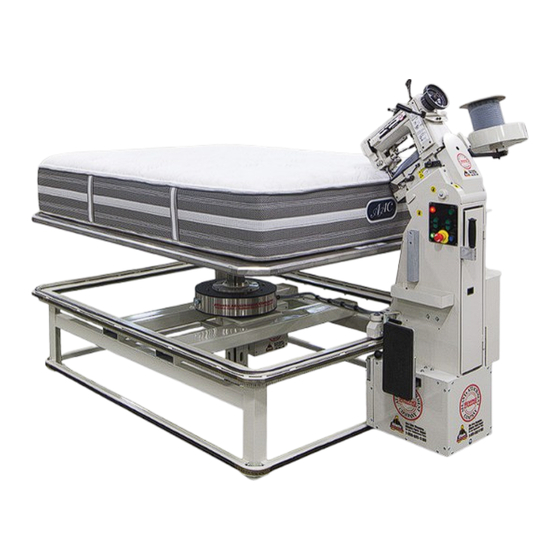
- Page 1 Model 1345-2B Revision 20.6 Updated 10/11/2023 Technical Manual & Part List Atlanta Attachment Co. 362 Industrial Park Drive Lawrenceville, GA 30046 +1 (770-963) 7369 www.atlatt.com...
- Page 3 Company. In addition to any confidentiality and non-disclosure obligations that currently exist between you and Atlanta Attachment Company, your use of these materials serves as an acknowledgment of the confidential and proprietary nature of these materials and your duty not to make any unauthorized use or disclosure of these materials.
-
Page 4: Table Of Contents
Content CONFIDENTIAL AND PROPRIETARY INFORMATION ............0 CONTENT ........................... 1 IMPORTANT SAFETY INSTRUCTION ................... 5 SAFETY EQUIPMENT ON THE MACHINES ................... 7 PROTECTIVE EYEWEAR ......................8 IMPORTANT NOTICES ......................... 9 MAINTENANCE .......................... 11 REPAIR ............................12 A WORD TO THE END USER ...................... 13 SAFETY PRECAUTIONS ...................... - Page 5 Lower Threading ........................25 Thread Tension Adjustment....................25 Needle Thread Tension ..........................25 Looper Thread Tension ..........................25 Threading the Tape....................... 26 2.3............................ 27 EWING 2.4.......................... 28 AINTENANCE General Security Instructions ....................28 Preparation ..........................28 Preventive Maintenance 8 Hours .................... 29 Lubrication Sewing Head Daily ....................
- Page 6 Preparation ..........................58 Preventive Maintenance 40 Hours..................59 Preventive Maintenance 160 Hrs.................... 60 Preventive Maintenance 1.920 Hrs ..................61 3.5........................62 ROUBLESHOOTING 3.6......................... 64 ORTALITY 3.7..........................66 RAINING SINGER® 300UX6 ASSEMBLY DRAWINGS & PARTS LISTS ............67 UPPER SHAFT ASSEMBLY ......................
- Page 7 1345-2AWD WIRING DIAGRAM ....................122 NOTES: ........................... 125 3.8. INDEX ..........................126...
-
Page 8: Important Safety Instruction
Mandatory Information All persons operating and/or working on the 1345-2B Tape Edge Machine should read and understand all parts of the Safety Instructions. This applies, in particular, for persons who only operate and/or work on the unit occasionally (e.g. for maintenance and repair). Persons who have difficulty reading must receive particularly thorough instruction. - Page 9 Operation Instructions Liability The machine should only be operated when in perfect working order, with due regard for safety and the potential dangers, as well as in accordance with the Instruction Material. Faults and malfunctions capable of impairing safety should be remedied immediately. We cannot accept any liability for personal injury or property damage due to operator errors or non-compliance with the safety instructions contained in this booklet.
-
Page 10: Safety Equipment On The Machines
Operation Instructions A Word to the Operator The greatest danger inherent in our machines: is that of fingers, hands or loose clothing being drawn into a machine by live, coasting or rotating tools or assemblies or of being cut by sharp tools or burned by hot elements. LWAYS BE CONSCIOUS OF THESE DANGERS Safety Equipment on the Machines All machines are delivered with safety equipment, which shall not be removed or bypassed during... -
Page 11: Protective Eyewear
Operation Instructions Protective Eyewear Protective eyewear that has been tested by the local authorities should be worn whenever there is a possibility of loose or flying objects or particles such as when cleaning the machine with compressed air. Tools Always count the number of tools in your possession before starting work on the machine. This will allow you to check that no tools have been left behind inside the machine. -
Page 12: Important Notices
Operation Instructions Important Notices Reporting and Fighting Fires Read the instructions posted in the factory with regard to reporting fires and the emergency exits. Make sure you know exactly where the fire extinguishers and sprinkler systems are located and how they are operated. - Page 13 Operation Instructions - Kinetic energy - Note that some motors or spindles, for example, may continue to run or coast run on after being switched off. - Potential energy - Individual assemblies may need to be secured if necessary for repair work. Delivery of the Machine/Packaging Note any markings on the packaging, such as weights, lifting points and special information.
-
Page 14: Maintenance
Operation Instructions Protect against influences from the surroundings: no structure-borne vibrations, no grinding dust, or chemical vapors. Protect against unauthorized access. Ensure that the machine and accessories are set up in a stable position. Ensure easy access for operation and maintenance (Instruction Manual and layout diagram); also verify that the floor is strong enough to carry the weight of the machine. -
Page 15: Repair
Operation Instructions Repair Replacement Parts We cannot accept any liability whatsoever for damage due to the use of parts made by other manufacturers or due to unqualified repair or modification of the machine. Repair, Electrical The power supply must be switched off (master switch off) and secured so that it cannot be switched on again inadvertently before starting any work on live parts. -
Page 16: A Word To The End User
Operation Instructions Starting Machine Movements Read the Instruction Manual carefully to establish which keys and functions start machine movements. A Word to the End User The end user has sole responsibility to enforce the use of safety procedures and guards on the machine. Any other safety devices or procedures due to local regulations should be should be retrofitted in accordance to these regulations and/or the EC Directive on the safety of machines. -
Page 17: Instalation
Operation Instructions INSTALLATION NOTE: It is important that the machine technician read this manual and be familiar with all the safety functions and concerns of the unit before installing and operating. 1.1. Parts & Components 1.- Sewing Head 6.- Speed Control 2.- Table 7.- Locking Lever 3.- Roll Holder... -
Page 18: Technical Data
Operation Instructions 1.2. Technical Data Description Unit Cost Max Sewing Speed 3.000 Sewing Head Model Singer 300UX6 Factory Preset Speed 2.700 Maximum Stitch Length Needle System SN62X5924 Needle Size 24/180 Weight of the Material MEDIUM/ HEAVY Max Presser Foot lift Inches 7/16 Voltage... -
Page 19: Machine Identification Tag
Operation Instructions 1.4. Machine Identification Tag The identification of the machine is located on the top of the table behind the sewing head. Its content is the machine class and the Serial Number. Ex: 218427031707 The serial number is divided as follows: The first number identifies the order number, 218427 The next number the month of manufacture, (03) The next number the year of manufacture, (17) -
Page 20: Types Of Machines & Subclasses
Operation Instructions 1.6. Types of Machines & Subclasses... -
Page 21: Assembly
Operation Instructions 1.7. Assembly • Remove all shipping belts from the machine. • Inspect the machine for any damage that may have occurred during shipment. If damage is found, report this immediately to your supervisor. Document the damage and provide details and photographs •... -
Page 22: Tape Roll Holder
Operation Instructions 4. Tape Roll Holder Install the tape roll holder 5. Power Connection Connect the power cord to 208-230 Vac, single-phase. 5 Amps. Lower table wiring meets UL standards. NOTE: It is important that the green wire is connected to ground 6. -
Page 23: Operation
Operation Instructions OPERATION Note: It is important that the operator of the machine read this manual and be familiar with all the functions and safety concerns of the unit before operating. 1.- Sewing Head 7.- Table 13.- Start Button 14 – Head Tilt 2.- Control Panel 8.- Roll Holder 3.- Disengage Button... -
Page 24: Individual Components
Operation Instructions 2.1. Individual Components 1. Sewing Head The 1345-2B unit designed for tape edge borders is supplied with a sewing head Model SSIN330UX6. Threading, curb, needles, etc. is explained later in this manual. 2. Control Panel It is located on the transport carriage easily accessible to the operator. -
Page 25: Car Blocker
Operation Instructions 6. Car Blocker This lever has the function of locking the carriage in a fixed position. It is used for transport and to sew in a static way. In normal operation you must keep the car released. 7. Table It is responsible for supporting the mattress during the binding operation. -
Page 26: Head Tilt
Operation Instructions 14. Head Tilt Its function is to tilt the sewing head to facilitate the stitching of the mattress. 15. Elevation Table Its function is to raise or lower the table at the height of the sewing needle. The table is adjustable from 25 "to 38"... -
Page 27: Preparation For Sewing
Operation Instructions 2.2. Preparation for Sewing NOTE:Please follow all safety procedures; it is recommended to turn off the machine. 1. Change of Needle Turn the pulley of the machine towards the operator until the needle bar is at its highest point. Loosen the needle pressure screw. -
Page 28: Lower Threading
Operation Instructions 3. Lower Threading Open the front table section, remove the bed slide and turn the machine pulley over toward the operator until the needle bar is at its highest point. Move the looper throw-out gear locking plunger rod and looper throw-out rack rod, Fig.7, out as far as possible. -
Page 29: Threading The Tape
Operation Instructions 5. Threading the Tape. a. Place the roll of tape in the roll holder. b. Thread the tape through the tape tensioner c. Use the pre-tensioning fingers if necessary. d. Cut the end of the tape at an angle and thread the fabric folder. -
Page 30: Sewing
Operation Instructions 2.3. Sewing Place a mattress on the table. Press the table height button (15) until the needle is level with the edge of the mattress. Tilt the head if necessary with the head tilt button (14) b. Move the mattress closer to the sewing machine. Lift the presser foot and place the mattress cover and the edge inside the edging tape. -
Page 31: Maintenance
Operation Instructions 2.4. Maintenance It is important that the operator of the machine read this manual and be familiar with all the functions and safety concerns of the unit before operating. General Security Instructions Maintenance should only be carried out by trained and qualified personnel. Turn off power, pneumatics, etc. -
Page 32: Preventive Maintenance 8 Hours
Operation Instructions Preventive Maintenance 8 Hours Preventive Maintenance Model: 11345-2B Materials Required Serial #: Oilcan with metal tip Operation: Tape Edge Sewing machine Oil Sew Head: Singer 300UX6 Lubricant Mobil Glygoyle 460 Serial #: Clean cloth, Compressed air Needle: SN 62x59 180/24 Silicon-based grease Before starting the day's shift with "The Machine Off"... -
Page 33: Lubrication Sewing Head Daily
Service Instructions Lubrication Sewing Head Daily The 300U class machines have a semi-automatic lubrication system consisting of a hollow shaft in the arm and a hollow shaft in the bed that act as oil reservoirs. The oil is distributed to all the main bearings by centrifugal force through the small channels in the shafts when the machine is in... - Page 34 Service Instructions...
-
Page 35: Service
The following references provide information about the LOTO process. Equipment Energy Control Procedure Lockout/Tag out Program Description: Tape Edge Model: 1345-2B Manufacturer: Atlanta Attachment Co. Location Magnitud Energy Location Control Method Electrical... -
Page 36: Mechanical Adjustments
Service Instructions 3.2. Mechanical Adjustments NOTE: All maintenance must be carried out by a qualified service technician. It is important that the operator read this manual and become familiar with all the safety features and functions of the unit before using Table Adjustment 1. -
Page 37: Alignment And Level
Service Instructions Lower the table until the bottom of the table is visible at the bottom of the column guide (a) Slightly tighten the two upper adjustment screws "D" in order to move the pads to the inner side. Raise and lower the table with the corresponding switch verifying that it moves freely. -
Page 38: Carriage Adjustment
Service Instructions Carriage Adjustment Locking Lever To transport the machine it is recommended to block the car using the locking knob. In case of sewing mattresses or very light mattresses it is common to block the car and disconnect the clutch using the button 12 of the control panel. -
Page 39: Sewing Head Adjustments
Service Instructions Sewing Head Adjustments 1. Pressure of the Presser Foot The pressure on the material should be as light as possible but it is still sufficient to ensure correct feeding. Alternating Pressure To decrease the pressure, loosen the lower fixing nut and loosen the locking screw, then tighten the upper fixing nut, see fig. -
Page 40: Alternating Presser Adjustment
Service Instructions 4. Alternating Presser Adjustment Rule: The height and elevation of the pressers is controlled by an adjustable eccentric. For coarse material a greater movement is necessary, for light materials a minor movement is recommended. Limiting the elevation of the presser foot to a minimum required for the job allows higher speeds. -
Page 41: Adjustment Of The Feed Dog
Service Instructions 7. Adjustment of the Feed Dog Centralizing the Feed Dog Sidewise Setting Rule: The feeding tooth must have the same opening distance with respect to the needle plate at both ends of the feed path. Adjustment: To adjust, set the feed to the desired length of the stitch. -
Page 42: Needle Bar Adjustment
Service Instructions 8. Needle Bar Adjustment Needle Bar Positioning Rule: The needle should enter the needle hole of the feed dog with equal distance to the front as towards the lateral sides of the feed dog (a = b = c). Adjustment: To adjust, press the needle bar rock frame, Fig. -
Page 43: Adjusting The Loopers
Service Instructions 10. Adjusting the Loopers Setting the Distance from the Looper to the Needle Rule: When the needle is at its bottom dead center and the looper at its rear dead center the distance between the looper tip and the center of the needle (2) should be around 4.8 mm or 3/16 inch. - Page 44 Service Instructions Sidewise Setting Rule: When correctly set: the point of the looper should be directly opposite of the center of the needle, and at the center of the clearance above the eye of the needle when the looper timing mark LT on the machine pulley is opposite of the timing arrow on the arm.
- Page 45 Service Instructions Longitudinal Fine Adjustment and Adjustment of the Height of the Needle Bar Rule: When properly fixed, when rotating the machine in the direction of rotation aligning mark Handwheel with the chassis mark of the machine, the point of the locker must be at the front end of the needle, 2 millimeters high with regarding the upper part of the eye of the needle.
-
Page 46: Thread Controls
Service Instructions 11. Thread Controls Positioning Spreader Sidewise and Height Setting Rule: When the looper on its forward stroke is passing the spreader a) The point of the spreader should be exactly opposite the top of the thread groove at the left side of the looper. - Page 47 Service Instructions Adjusting Needle Thread Take- Rule: The needle thread take-up and thread guide may be adjusted to increase or decrease the amount of thread drawn at the top of the needle bar stroke Adjustment: To increase the amount, loosen the thread take-up screw, Fig.
- Page 48 Service Instructions...
-
Page 49: Tape Edge Folders
Service Instructions Tape Edge Folders There is a wide variety of fabric folders It is recommended that the folders matches the width of the tape. The folder has a stamped marking that corresponds to the measurement of the tape and the opening of the mouth. -
Page 50: Electrical Adjustments
Service Instructions 3.3. Electrical Adjustments NOTE: All maintenance must be performed by a qualified service technician. Ground This unit needs to be grounded for several reasons. In equipment powered by the network, exposed metal parts are connected to ground to prevent user contact with dangerous voltage when electrical insulation fails. -
Page 51: Electric Transmission Ring
Service Instructions Electric Transmission Ring Located at the bottom of the table. It transmits the energy from the electrical input box to the main electrical box. It has 8 contact tracks as well as 8 brushes. a. Lubrication All bearings are lubricated for life in the Factory. b. - Page 52 Service Instructions Adjustment of the Brush The brushes should run at 90 degrees +/- 3% square on the rings. If the brush is not square, adjust the position of the brush holder on the brush post. It is not necessary that the brushes run in the center of the rings, but there must be no forced friction against the insulators.
-
Page 53: Main Distribution Box
Service Instructions Main Distribution Box It is located in the back of the car. To access the panel an access key is required. a. Secondary Switch. It serves as protection to the distribution box. It should always be b. Sewing Relay It is activated during the sewing cycle. - Page 54 Service Instructions...
-
Page 55: Speed Potentiometer
Service Instructions Each unit of the SCL / SCM Series has an Electronic Programming Module (EPM) installed on the main control board. The EPM stores the user's parameter settings and the OEM's special default configuration (if programmed). The EPM is removable, which allows its installation in another unit for a quick configuration. -
Page 56: Motors
Service Instructions Motors The 1345-2 unit has 3 motor a. Sewing and Car Located at the bottom of the car. The speed of the motor is controlled by the speed controller in the control box. It has two pulleys. The first transmits the rotation movement to the sewing head and the second to the clutch system b. - Page 57 Service Instructions • Separate components • Check that the brake system is free of grease. There must be friction between the fiber discs and the bronze plate. If necessary, replace the brake. Part #: MM14245-002 BRAKE F/MOTION SYSTEM 2. Armed Place the brake in its cavity •...
-
Page 58: Knee Pad
Service Instructions Knee Pad The operator controls the movement of the car through the use of the knee. The contact plate is adjustable in height after loosening the four screws (a). For lower operators, if necessary, you can move the screws to position "b" The kneepad connects to the speed controller. - Page 59 Service Instructions...
-
Page 60: Electronic Clutch
Service Instructions Electronic Clutch Located in the lower part of the cart cabinet. It is an electronic brake free of maintenance. Avoid the drop of oil or any liquid inside It has three movable plates and six friction surfaces. In case it is necessary to replace the clutches the replacement kit is: MM231631-KIT1 Maintenance of the Reduction Box •... -
Page 61: Maintenance
Service Instructions 3.4. Maintenance It is important that the operator of the machine read this manual and be familiar with all the functions and safety concerns of the unit before operating. General Security Instructions Maintenance should only be carried out by trained and qualified personnel. Turn off power, pneumatics, etc. -
Page 62: Preventive Maintenance 40 Hours
Service Instructions Preventive Maintenance 40 Hours. Preventive Maintenance Model: 11345-2B Materials Required Serial #: Oilcan with metal tip Operation: Tape Edge Sewing machine Oil Sew Head: Singer 300UX6 Lubricant Mobil Glygoyle 460 Serial #: Clean cloth, Compressed air Needle: SN 62x59 180/24 Silicon-based grease .- Unscrew the covers and with an air gun blow out all the accumulated dirt... -
Page 63: Preventive Maintenance 160 Hrs
Service Instructions Preventive Maintenance 160 Hrs. Preventive Maintenance Model: 11345-2B Materials Required Serial #: Oilcan with metal tip Operation: Tape Edge Sewing machine Oil Sew Head: Singer 300UX6 Lubricant Mobil Glygoyle 460 Serial #: Clean cloth, Compressed air Needle: SN 62x59 180/24 Silicon-based grease .- Check the tension and condition of the belt on the bottom motor. -
Page 64: Preventive Maintenance 1.920 Hrs
Service Instructions Preventive Maintenance 1.920 Hrs. Preventive Maintenance Model: 11345-2B Materials Required Serial #: Oilcan with metal tip Operation: Tape Edge Sewing machine Oil Sew Head: Singer 300UX6 Lubricant Mobil Glygoyle 460 Serial #: Clean cloth, Compressed air Needle: SN 62x59 180/24 Silicon-based grease .- Check if there is any play in the carriage against the table and... -
Page 65: Troubleshooting
Service Instructions 3.5. Troubleshooting Problem Cause: Corrective Action Machine does not turn on • Electrical fault • Check that the green light on the electrical box under the table is on • Check that the switch inside the main box is activated •... - Page 66 Service Instructions Problem Cause: Corrective Action • • You have to constantly Table is not well leveled with reference Refer to the table setting in the manual adjust the table height to its structure while sewing • • Check the brake plate of the clutch motor. Refer Table loses height during The table motor brake is defective sewing...
-
Page 67: High Mortality Kit
Service Instructions 3.6. High Mortality Kit. The machine is offered as an option with a set of high mortality parts recommended for the natural consumption of the machine. . The content of the kit is as follows: Kit de Parts #: SP13452A1 Station 1345-2 TAPE EDGE WORKSTATION... - Page 68 Service Instructions Item Part Number Description BLOCK,PUSH BUTTON CONTACT N.C. F/3 ACROSS EE3X01 MOUNTING BLOCK,PUSH BUTTON CONTACT N.O. F/2 ACROSS EE3X10 MOUNTING EECA491024 CONTACTOR,MINI,240V EED5N157 LAMP,INC,BAYONET,24V,1.4W EEK10P11D1 RELAY,24VDC,DPDT 15A-AC,PLUG-IN EERHU02800 HOLDER,BRUSH EERHU45066C BRUSH FOR SLIP RING ASSY EERHU-B08 FF002304A LINEAR TRANSDUCER ASSY 1345 FF2938947 POWER SUP,SWITCHER,24 V 1.5A,85-265 VAC,DIN RAIL FFL722C...
-
Page 69: Training
Service Instructions 3.7. Training Activity Time Safety Instructions 5 min Use of the Manual 5 min INSTALATION 3 Horas. OPERATION 30 min Control Panel PREPARATION 2 Hr. Thread Threading Tape Threading Tension Adjustment Preventive Maintenance 8hrs 15 min SERVICE 5 min Lockout/Tag out Program MECANIC 4 Horas... -
Page 70: Singer® 300Ux6 Assembly Drawings & Parts Lists
Service Instructions Singer® 300UX6 Assembly Drawings & Parts Lists Atlanta Attachment Company is the exclusive stocking distributor for Singer Tape Edge Sewing Heads and recommended spare parts for Singer Tape Edge machines. We can also supply proprietary parts in most cases for Cash*, Spuhl*, Porter, United* Tape Edge workstations. - Page 71 Service Instructions...
-
Page 72: Upper Shaft Assembly
Service Instructions Upper Shaft Assembly NO. PART # DESCRIPTION NO. PART # DESCRIPTION 32 415077 415138 CRANK, NEEDLE BAR LIFTING ECC FLANGE 32848 BEARING 33 374098 SCREW 2812239 NEEDLE BAR CRANK COMPLETE 34 415081 ECCENTRIC COMP 549024 SCREW 35 268491 LIFTING ECCENTRIC 544358 SET SCREW... - Page 73 Service Instructions...
-
Page 74: Front Assembly Sewing Arm
Service Instructions Front Assembly Sewing Arm NO. PART # DESCRIPTION NO. PART # DESCRIPTION 25 414545 267617 LINK HINGE PIN SET SCREW 268258 PACKING WICK 26 267657 VIB PRESSER BAR 267627 LIFTING LINK 27 267658 VIBRATING PRESSER BAR HINGE ST 415061 LIFTING CRANK 28 281912... - Page 75 Service Instructions...
-
Page 76: External Parts Sewing Arm #1
Service Instructions External Parts Sewing Arm #1 NO. PART # DESCRIPTION 32788 ROCK SHAFT 32788 ROCK SHAFT 32789 ROCK SHAFT 548035 141424 SCREW 267110 NEEDLE BEARING,GBH-78 415065 COLLAR COMP 504020 SCREW (300UX5) 415069 CONN CRANK 414509 SCREW 374362 SUBSTITUTION REQUIRED 267617 LINK HINGE PIN 268258... - Page 77 Service Instructions...
- Page 78 Service Instructions Lower Shaft Assembly NO. PART # DESCRIPTION NO. PART # DESCRIPTION 34 541197 415176 DRIVE CRANK 374099 SCREW 35 545297 SCREW 500264833 LOOPER DRIVING CRANK SET SCREW 36 415082 ECCENTRIC COMP 268102 COVER, OIL HOLE 37 415073 FEED DRIVING ECC FLANGE 414563 SCREW 38 415073...
- Page 79 Service Instructions...
-
Page 80: Front Assembly Sewing Bed
Service Instructions Front Assembly Sewing Bed NO. PART # DESCRIPTION NO. PART # DESCRIPTION 28 281208 559061 FEED DOG LOOPER COMPLETE WITH GUARD 267665 LOOP DEFLECTOR 29 268382 LOOPER ONLY (ORDER 281207 FOR 412176 LINK, CONN CRANK 30 281207 NEEDLE GUARD 559064 FEED DOG SHANK 31 141478... - Page 81 Service Instructions...
-
Page 82: Cross Shaft In Sewing Bed
Service Instructions Cross Shaft in Sewing Bed NO. PART # DESCRIPTION 281975 SPREADER 268162 SPREADER POINT 414552 SCREW 547670 WASHER 415196 SPREADER HOLDER 414529 SCREW 268184 SPREADER BAR BRACKET 414524 SCREW 559065 SPREADER BAR 268190 SPREADER DRIVE PIN 415297 BUSHING 415389 ROCK SHAFT 415194... - Page 83 Service Instructions...
-
Page 84: External Parts Sewing Arm #2
Service Instructions External Parts Sewing Arm #2 NO. PART # DESCRIPTION KE0085 FOOT LIFTER LEVER 201363 SCREW 300W 267707 RELEASING PLATE 543850001 PLATE PIN 414577 HINGE SCREW 543804004 WASHER 541166003 204348 SWITCH SPRING 414570 SCREW 544336 STUD SCREW 267704 LIFTER LEVER ROD 248423 COTTER PIN 267650... - Page 85 Service Instructions...
-
Page 86: External Parts Sewing Arm #3
Service Instructions External Parts Sewing Arm #3 NO. PART # DESCRIPTION 268506 TH GUIDE BRACKET 268111 LOOPER BRACKET 268505 LOOPER TH GUIDE 50169 SCREW (5) 414537 SCREW 544875 PLUG 267971 THREAD TENSION HA046072 TENSION DICS 32572 TENSION DISC (5) 59538 SPRING BUSHING 131741 TENSION SPRING... - Page 87 Service Instructions...
- Page 88 Service Instructions External Parts Sewing Arm #4 NO. PART # DESCRIPTION KE0021 FACE PLATE (WITH 268033) 268330 FACE PLATE HINGE STUD 544053 SET SCREW 268033 LOCK STUD 228661 COVER CUSHION 268032 LOCK SPRING 415016 SPRING PLATE 414534 SCREW KE0072 ARM SIDE COVER 545295 SCREW 267656452...
- Page 89 Service Instructions...
-
Page 90: External Parts Sewing Arm #5
Service Instructions External Parts Sewing Arm #5 NO. PART # DESCRIPTION KE0073 BED PLATE (RIGHT) 414508 SCREW KE0037 BED PLATE (LEFT) 559060 THROAT PLATE 374107001 THROAT PLATE SCREW (BACK) 200100 SCREW KE0075 FEED REGULATING STUD SOCKET 268081 STUD, FEED REG 270026 FEED REG STUD SPR 240245... - Page 91 Service Instructions Accessories...
-
Page 92: Ssembly / Adjustment Instructions
Service Instructions SSEMBLY / ADJUSTMENT INSTRUCTIONS 1. Position the column assy (item A) with the lower edge below the bottom of the slide support bracket (item B). DO NOT ADJUST WITHT THE COLUMN OR TABLE IN THE "UP" POSITION. 2. Loosen the (8) screws (item C) holding the slide support bracket (item B) and the jam nuts (item D) for the top and bottom adjustment screws (item E). -
Page 93: Assembly Drawings & Parts Lists
The materials contained herein are confidential and proprietary information of Atlanta Attachment Company. In addition to any confidentiality and non-disclosure obligations that currently exist between you and Atlanta Attachment Company, your use of these materials serves as an acknowledgment of the confidential and proprietary nature of these materials... - Page 94 Service Instructions 11345-2B Tape Edge Machine AAC Drawing Number 9001371 Rev 6 PART# DESCRIPTION 1345-2AWD WIRING DIAGRAM 1345232 SPACER, CAM FOLLOWER 13452500A TABLE ASSY, COMPLETE 13453000C CARRIAGE ASSEMBLYY 13453428 MOUNT, CAM FOLLOWER 1345LAB1 LABEL 1345LAB2 LABEL,TABLE,DON'T MMCCF3/4SB CAM FOLLOWER,3/4 DIA SIT/STAND SSHC01048GR8 1/4-20 X 3/4 HEX CAP...
-
Page 95: 11345-2E Tape Edge Machine
Service Instructions 11345-2E Tape Edge Machine ACC Drawing Number 192155B Rev 2 QTY PART # DESCRIPTION 13452500A Complete Table Assy. 13453000C Carriage Assy. 13453428 Cam Follower Mount AR 1345-2AWD Wiring Diagram AR 1345LAB1 Label AR 1345LAB2 Label MMCCF3/4SB Cam Follwer SSHC01048GR8 Hex Head Screw SAAC-300UZ5... -
Page 96: 13452500A Frame Lift Assembly & Tablet
Service Instructions 13452500A Frame Lift Assembly & Tablet AAC Drawing Number 9001366 Rev 11 QTY PART # DESCRIPTION 13451000 BASE ASSY LIFT TABLE TAPE 13451200 TABLE TOP ASSY,QUEEN 13452000D COLUMN, LIFT ASSY 13452027 LINK, CABLE ASSY,TWIN BBTRA613 WASHER,THRUST,STL, .375B NNJ5/16-18 NUT,JAM,5/16-18 PPP2217 WIRE CLAMP, .337I.D. -
Page 97: 13451000 Lift Table Base Assembly
Service Instructions 13451000 Lift Table Base Assembly AAC Drawing Number 9001365 Rev 7 QTY PART # DESCRIPTION 0411-1063 ROD, THREADED, 5/8-11 X 5 1345027 FRAME, WELDMENT TAPE EDGE 13451019 GEAR RACK, SHORT 13451020 GEAR RACK, LONG 13451021 GEAR RACK, CORNER 13451029 PAD, RUBBER 13459500... - Page 98 Service Instructions...
- Page 99 Service Instructions...
-
Page 100: 13459500 Control Box
Service Instructions 13459500 Control Box AAC Drawing Number 9001947 Rev 1 QTY PART # DESCRIPTION 13459004A MOUNTING BRACKET, CAPACIT 13459501 PANEL,HIGH VOLTAGE 13459503 COVER, ELECTRICAL PANEL 40-322 BOTTOM, AC POWER LOCKOUT 40-323 TOP, AC POWER LOCKOUT EEAK42BS RIVET,BLIND 1/8 DIA ALUM. EECA491024 CONTACTOR, MINI, 240V EECLIPFIX... - Page 101 Service Instructions...
-
Page 102: 13452000D Column Lift Assembly
Service Instructions 13452000D Column Lift Assembly AAC Drawing Number 9002809 Rev 4 ITEM NO. QTY. PART NUMBER DESCRIPTION 1345093 BKT,EDGE GUIDE 1345130 TOP MOD.,SLIP RING 1345131 PLATE,SLIDE, ADJ 1345132 BAR, BRACE,.25 THK 1345134 SPACER,COLUMN CONCAVE 1345135 PLATE, SLIDE 1345136 BKT,LOW ER GIB STOP 1345231 COLUMN ASSY 1345234... -
Page 103: 13453000C Carriage Assembly
Service Instructions 13453000C Carriage Assembly AAC Drawing Number 9003228 Rev 2... - Page 104 Service Instructions PART# DESCRIPTION PART# DESCRIPTION 1345-2AWD WIRING DIAGRAM MMSLD- 1/2" DIA RUBBER 1345049 SHIM. .015 S/S NNH1/4-20 NUT,HEX,1/4- 1345162 PLATE, MOUNTING NNH3/8-16 NUT,HEX,3/8- 1345163 COVER,CARRIAGE,FR NNH5/8-18 NUT,HEX,5/8- 1345168 SPACER, GEARBOX NNK1/4-20 NUT,HEX,KEP, 1/4-20 13453003 COVER,CARRIAGE, SSBC9001 8-32 X 1/4 REAR BUTTON CAP 13453060...
-
Page 105: Aac 13453300A Top Carriage Assembly
Service Instructions AAC 13453300A Top Carriage Assembly Drawing Number 9001268 Rev 15 See next page... - Page 106 Service Instructions 13453300A parts list NO. QTY PART # DESCRIPTION NO. QTY PART # DESCRIPTION 029-003A PLATE, NUT, 1/4-20 @ 1.50 MM98335A064 SPRING CLIP 13453064 COVER, BELT, UPPER MMCYR114S FOLLOWER, CAM 13453065 COVER, BELT, LOWER MMGP-105 GRIP HANDLE-FOAM 3/4 ID 13453100A CARRIAGE, FRAME ASSY.
- Page 107 Service Instructions...
-
Page 108: 13453370 Knee Switch Assembly
Service Instructions 13453370 Knee Switch Assembly AAC Drawing Number 9000382 Rev 5 QTY PART # DESCRIPTION 1345100 KNEE SWITCH ASSEMBLY 13453332A BRKT.,KNEE SENSOR A-2014-39 MICRO SWITCH MODIFIED SSHC90032S #8-32 X 1/2 HEX CAP SSPS70032 #4-40 X 1/2 PAN HD SLOT WWF8 WASHER, FLAT #8 WWL8... - Page 109 Service Instructions...
-
Page 110: 1345100 Knew Switch Assembly
Service Instructions 1345100 KNEW SWITCH ASSEMBLY AAC Drawing Number 1345100 NO QTY PART # DESCRIPTION 1345101 PLATE,TRANSDUCER END 1345102 MOUNT, TRANSDUCER 1345103 PLATE,SPRI NG,TRANSDUCER 1345104 CLAMP,TRANSDUCER 13453306 BLOCK,RAI L STOP 13453309 RAI L BKT ASBLY 13453337 BRACKET,RAI L SUPPORT 13453361 BRKT, SPRI NG TENSI ON FF002304A LI NEAR TRANSDUCER ASBY... -
Page 111: 13453390A Motor Assembly
Service Instructions 13453390A Motor Assembly AAC Drawing Number 9001194 Rev 5 PART # DESCRIPTION 1345156 SPACER 13453328 PLATE, MOTOR MOUNT EE14-4 CABLE,4 COND,14 AWG,SJOOW EE4RX36 MOTOR,I NVERT DUTY,1HP FF3460 STRAI N RELI EF,LI Q TI GHT FF8465 NUT,LOCK,3/4NPT,NYLON,BLK PPM631M1 PULLEY, V BELT, MOTOR, 3.75 OD, MOD SSHC01048 1/4-20 X 3/4 HEX CAP SSHC01064... -
Page 112: 1345-500 Footlift Pivot Link Assembly
Service Instructions 1345-500 Footlift Pivot Link Assembly AAC Drawing Number 192500B Rev 7 QTY PART # DESCRIPTION 1349518 Foot Lift Lever 1345-503 Pivot Bracket 1345077 Stop Clamp 1345-504 Pivot Arm MMBTH-2 Handle SSSC98048 Screw, Socket Cap AR 1345-500INS Instructions... - Page 113 Service Instructions...
-
Page 114: 13453400A Carriage Guide Assembly
Service Instructions 13453400A Carriage Guide Assembly AAC Drawing Number 9001193 Rev 6 QTY PART # DESCRIPTION 13453401A CARRIAGE GUIDE FRAME ASSY 13453404 ROLLER YOKE ASSY 13453408 GUIDE ARM ASSY. 13453411 STUD, ROLLER BEARING 13453413 ROLLER, GUIDE 13453414 HUB, ROLLER GUIDE 13453415 PLATE, CABLE HOLDER 13453416... - Page 115 Service Instructions...
-
Page 116: 13453500E Gear Box Assembly
Service Instructions 13453500E Gear Box Assembly AAC Drawing Number 9003675 Rev.0 PART # DESCRIPTION 132556-258 KEY, 3/16 X .813 L 1345041 NUT PLATE,1/4-20X3.25 1345167 BRKT, GEAR BOX, LOWER 1345176 BLOCK, BEARING MOUNTING 1345178 PLATE,GEAR BOX 1345359 SHIM, BEARING MOUNTING 13453501 PLATE, CLUTCH ADAPTER 13453503B SHAFT, GEAR DRIVE... - Page 117 Service Instructions...
-
Page 118: 13459000 Carriage Control Box Assembly
Service Instructions 13459000 Carriage Control Box Assembly AAC Drawing Number 9001144 Rev 9 PART # DESCRIPTION 1345LAB1 LABEL 13459001 SUB PANEL, CARRIAGE 13459003A BRKT, MOUNTING, 2 POT, -2 13459004A MOUNTING BRACKET, CAPACIT 13459006 CONTROL BOX 11345 13459008 POT,5K,1 TURN,PNL.,.5W *2.5 FT EE14-4 CABLE,4 COND,14 AWG,SJOOW EE20C297 RETAINING SPRING... -
Page 119: 13453800 Gear Lock Assembly
Service Instructions 13453800 Gear Lock Assembly AAC Drawing Number 9001130 Rev 1 QTY PART # DESCRIPTION 13453801 SUPPORT GEAR LOCK ASSY. IIS012X096 SPRING PIN, 3/16X1.5 MM61095K53 KNOB, BALL,3/8-16 TAP RRLC0742HJ SPRING, COMP. .072X.66X3 13453804 MANDREL,GEAR LOCK... -
Page 120: 13459300 Control Button Panel
Service Instructions 13459300 Control Button Panel AAC Drawing Number 9001107 Rev 2 NO. QTY PART # DESCRIPTION NO. QTY PART # DESCRIPTION 13452LAB LABEL,SWITCH PANEL EEPFA6 BUTTON, PUSH, BLU, FLUSH 13459301 PANEL, SWITCH EEPLE3 BUTTON, PUSH, GRN, ILLUM EE15Y PLATE, LEGEND, YELLOW EEPLE4 BUTTON, PUSH, RED, ILLUM EE3X01... -
Page 121: Sin-300Ux6A Tape Edge Head (11345-2B)
Service Instructions SIN-300UX6A Tape Edge Head (11345-2B) AAC Drawing Number 9001121 Rev 1 NO. QTY. PART# DESCRIPTION 1345-004 BLOCK, STOP FOR 1345-006S PULLEY,300UX5,SPUHL BINDER 1345-009A SPACER,1/8X1X1.8L 1345-009B SLEEVE,.25 ODX.19 1345-025 TAPE ROLL HOLDER IDX.5LS AAF11752-3 BRASS BARB FOR ASSY RRBEEHIVEH SPRING,HEAVY AIRLINE. -
Page 122: Saac-300Uz5 Tape Edge Head Modified (11345-2E)
Service Instructions SAAC-300UZ5 Tape Edge Head Modified (11345-2E) AAC Drawing Number 192137A Rev 1 NO. QTY PART # DESCRIPTION NO. QTY PART # DESCRIPTION 1345024 Left Bed Plate 1345-025 Tape Roll Holder 1345023 Right Bed Plate WWFS1/4 Flat Washer SCTE-300UB5 Sewing Head WWL1/4 Lock Washer 1345-004... - Page 123 Service Instructions...
-
Page 124: 1345096 Lockstitch Head Assembly (Optional)
Service Instructions 1345096 Lockstitch Head Assembly (Optional AAC Drawing Number 1345096 Rev 1 PART# DESCRIPTION PART# DESCRIPTION 1278-8301a PLASTIC IDLER NNK10-32 KEP NUT, 10-32 ROLLER 1345-004 BLOCK, STOP RRBEEHIVE SPRING,HEAVY BEEHIVE 1345-009B SLEEVE,.25 SJUKI- SEW HEAD,NOT ODX.19 ID LS1341 ACCURATE 1345-025 TAPE ROLL SSAS020048... - Page 125 Service Instructions 1345-2AWD Wiring Diagram...
- Page 126 (800) hours of operation or one hundred (100) days whichever comes first. Atlanta Attachment Company warrants all electrical components of the Serial Bus System to be free from defects in material or workmanship for a period of thirty six (36) months.
- Page 127 (800) horas de operación o cien (100) días cual llegue primero. Atlanta Attachment Company garantiza que todos los componentes del Serial bus son libres de defectos de material y de mano de obra durante un periodo de treinta y seis (36) meses.
- Page 128 Service Instructions Notes:...
- Page 129 Service Instructions 3.8. INDEX Accessories INSTALATION Roll Holder 14, 19, 20, 22 Activating Lever Axial Guides Safety Instruction knee actuator Knee Pad SERVICE Brushes Knee Switch 20, 21, 63, 101 Sewing Sewing Head14, 15, 18, 20, 21, 30, Shock Absorber Speed Control Car Blocker Locking Lever...
- Page 130 Service Instructions...
- Page 131 Service Instructions Atlanta Attachment Company Inc. 362 Industrial Park Drive Lawrenceville, GA 30046 Phone: +1 (770) 963-7369 www.atlatt.com Printed in USA Digital Version of this Manual Available at: http://atlatt.com/tech_manuals.php...
Need help?
Do you have a question about the 1345-2B and is the answer not in the manual?
Questions and answers