Table of Contents
Advertisement
Quick Links
Advertisement
Table of Contents

Related Manuals for Degelman RENN RMC-12 ELECTRIC


Summary of Contents for Degelman RENN RMC-12 ELECTRIC
- Page 1 RMC-12 ELECTRIC Operator’s & Parts Manual P.T.O. Model No. 911200-0220.06 RENN Mill Center LP. R.R. #4 Lacombe, Alberta, Canada T4L 2N4 Phone: (403) 784-3518 Fax : (403) 784-2060 Email : rennmill@rennmill.com www.rennmill.com Note: Motor not included.
-
Page 2: Table Of Contents
TABLE OF CONTENTS Table of Contents ................... 1.1 Introduction ....................1.3 Renn Warranty Policy .................. 1.4 Mill Serial Number Location ...............1.5 2 Safety ......................2.1 2.1 General Safety ..................2.2 2.2 Operating Safety ................2.3 2.3 Maintenance Safety ................2.3 2.4 Safety Decals .................. -
Page 3: Table Of Contents
TABLE OF CONTENTS 7 Troubleshooting Guide ..............7.1 8 Specifications ..................8.1 8.1 General Specifications ..............8.1 8.2 Bolt Torque Specifications .............. 8.1 8.3 Overall Dimensions ................8.3 9 Parts ....................9.1 9.1 Top Hopper ..................9.1 9.1.1 Knob ..................9.3 9.2 Roller Mill - Upper Half .............. -
Page 4: Introduction
INTRODUCTION Congratulations on your decision to purchase a Renn Roller Mill. This machine has been designed to provide you with the highest standards of quality, reliability and durability. This manual has been prepared to familiarize you with the opera- tion and maintenance of your mill. We urge you to read the publication carefully and refer to it extensively for correct operating procedure. - Page 5 LIMITED WARRANTY • • NEW EQUIPMENT WARRANTY WHAT YOU MUST DO TO ENFORCE THIS WARRANTY Subject to the limitations and exclusions set out herein, RENN Mill Center LP. Warranty services must be performed by a dealer authorized by Renn. (“Renn”) warrants that if any component or part of a machine manufactured by The purchaser must , at the purchaser’s expense, deliver, mail or ship Renn proves to be defective in material or workmanship within the defective part to any duly authorized dealer in the purchasers area.
-
Page 6: Mill Serial Number Location
MILL SERIAL NUMBER LOCATION The serial number plate is located on the inside face of the back panel of the top hopper, on the driver’s side of the machine. Note: Motor not included. IMPORTANT: For fast, correct service when ordering parts, provide the following information to your local Renn Dealer: 1) The model number 2) The serial number... -
Page 7: Safety
2 SAFETY Safety Alert Symbol This Safety Alert symbol The Safety Alert symbol identifies important means safety messages on the Renn Mill and in the manual. When you see this symbol, be alert to the possibility of ATTENTION! personal injury or death. Follow the BE ALERT! instructions in the safety message. -
Page 8: General Safety
2 SAFETY You are responsible for the SAFE operation and maintenance of your Renn Roller Mill. YOU must ensure that you and anyone else who is going to operate, maintain or work around the mill be familiar with the operating and maintenance procedures and related SAFETY information contained in this manual. -
Page 9: Operating Safety
2 SAFETY 2.2 Operating Safety 1. Read and understand the Operator’s Manual and all safety signs before using. 2. Place all controls in neutral, stop the motor, and wait for all moving parts to stop before ser- vicing, adjusting, repairing or unplugging. 3. -
Page 10: Safety Shield Placement
2 SAFETY 2.5 Safety Shield Placement After servicing or maintenance, these shields should be back in place. Front Shield Rear Shield Cam Shield Inspection Door - 2.4 -... -
Page 11: Sign-Off Form
2 SAFETY 2.6 Sign-off Form Make these periodic reviews of SAFETY Anyone operating and/or maintaining the and OPERATION a standard practice for all mill must read and clearly understand ALL of your equipment. We feel that an untrained of the Safety, Operating, and Maintenance operator is unqualified to operate this ma- information presented in this manual. -
Page 12: Decal Locations
3 DECAL LOCATIONS 3.1 Safety Decal Locations The types of safety decals and the locations on the equipment are shown in the following illus- trations. Good safety requires that you familiarize yourself with the various safety decals, the type of warning and the area, or particular function related to that area, that requires your SAFETY AWARENESS. - Page 13 3 DECAL LOCATIONS 3.1 Safety Decal Locations - 3.2 -...
-
Page 14: Information Decal Locations
3 DECAL LOCATIONS 3.2 Information Decal Locations The types of informational and operational decals and locations on the equipment are shown in the following illustrations. Good operation requires that you famil- iarize yourself with the various operational decals, the type of warning and the ar- ea, or particular function related to that area, that requires your AWARENESS. - Page 15 3 DECAL LOCATIONS 3.2 Information Decal Locations Note: Motor not included. - 3.4 -...
-
Page 16: Operation
4 OPERATION 4.1 To the New Operator or Owner The Renn Mill is designed to receive dry grain from an auger, process it, and deposit it via the discharge auger. Be familiar with the machine before starting. In addition to the design and configuration of equipment, hazard control and accident preven- tion are dependent upon the awareness, concern, and prudence of personnel involved in the op- eration, transportation, maintenance and storage of equipment or in the use and maintenance of facilities. -
Page 17: Setting Up The Roller Mill
4 OPERATION Setting up the Roller Mill 4.4.1 Roll Setting Figure 4.1 Figure 4.2 Loosen the wing nuts holding down the top hopper (Figure 4.2) and tip it over center, rotating on the hinge pin until it hits the stoppers. If using flat rolls to roll dry grain, set the rolls a very small distance apart. -
Page 18: Roll Gap Adjustment
4 OPERATION 4.4.2 Roll Gap Adjustment The cam control ( Figure 4.4) serves as a mechanism to make roll gap adjustments accurately and quickly using a 3/4” wrench or socket. The cam positional indicator is set at the factory to the “1”... -
Page 19: Feed Gate Control
4 OPERATION 4.4.3 Feed Gate Control Set the friction nut/washer (Figure 4.6) so that it supports the weight of the feed gate and yet allows the gate to be opened and closed by hand. Note that the setting of the feed gate helps to spread the feeding of grain evenly across the face of the roll. -
Page 20: Spring Pressure
4 OPERATION Roll Drive Belt Cross Auger Drive Belt Figure 4.8 Figure 4.9 4.4.7 Spring Pressure To increase spring pressure, loosen the jam nut and turn the spring push bolt inward a 1/4 turn at a time. Setting the pressure higher than necessary is hard on the bearings and the roll surfaces when hard particles like rocks go through the rolls. -
Page 21: Grate Magnet
4 OPERATION 4.4.8 Grate Magnet The grate magnet has slits on the edges (Figure 4.11). These can be removed with pliers to ex- pand the top opening. This modification may aid in improving material flow when milling wet grain. Figure 4.11 4.5 Operating the Roller Mill 1. -
Page 22: Break-In
4 OPERATION 4.6 Break-in It is recommended that the mill be run at moderate to full operational speed and at 1/2 to 2/3 capacity during the first hour of operation. This allows the frictional forces to diminish signifi- cantly within the auger tube, and allows the free flow of grain to approach acceptable levels in the system. -
Page 23: Service And Maintenance
5 SERVICE AND MAINTENANCE 5.1 Servicing Record See the Lubrication and Maintenance sections for details of service. Copy this page to con- tinue record. ACTION CODE: CL…….CLEAN T……...TIGHTEN L……….LUBRICATE CH…….CHECK Hours Serviced MAINTENANCE 50 Hours of Use Rolls Position - Square Cam Bearings Belt Tension Annually... -
Page 24: Servicing Intervals
5 SERVICE AND MAINTENANCE 5.2 Servicing Intervals Grease Use an S.A.E. multi-purpose high temperature grease with extreme pressure (EP) performance. An S.A.E. multi-purpose lithium base grease is also acceptable. Use the Maintenance Checklist provided to keep a record of all scheduled maintenance: 1. -
Page 25: Removal Of Rolls For Servicing
5 SERVICE AND MAINTENANCE 5.3 Removal Of Rolls For Servicing 1. With the power disconnected, loosen the jam nuts on each of the spring tension bolts and relieve all pressure from the spring (see section 4.4.7). 2. Relieve tension on the drive motor belts and remove. 3. -
Page 26: Pdi Setup
6 PDI SETUP Your Renn Mill comes with everything except motor and mounting hardware. Note: Use proper safety procedures while lifting heavy objects. - 6.1 -... -
Page 27: Troubleshooting Guide
7 TROUBLESHOOTING GUIDE PROBLEM CAUSE REMEDY Whole grain in sample Wear plate not adjusted. With power disconnected & rolls not rotating, use a 3/4” wrench to loosen the jam nut on the wear plate adjust- er. Adjust the wear plates in so that there is minimal clearance between the end of the rolls &... - Page 28 7 TROUBLESHOOTING GUIDE PROBLEM CAUSE REMEDY Wear plates and poly ‘V’, roll Grain smaller than the space Need finer groove pattern. gap & spring pressure set between the grooves. properly, still whole grain in Rolls need re-grooving or are sample no longer true (badly worn).
-
Page 29: Specifications
8 SPECIFICATIONS 8.1 General Specifications Weight……………...…………………………………...………………………………Electric - 2465 lbs Minimum Horsepower……………..………………………….…………………………...15 hp - Electric Machine Capacity.……………………………………………………up to 1250 bu/hr (dry corn) **Capacity will change with moisture content, roll configuration and particle size desired. 8.2 Bolt Torque Specifications Bolts For Taper - Locking Hubs - Rolls - See Page 9.10 All other bolts—Refer to Bolt Torque Chart on Following Page - 8.1 -... - Page 30 8 SPECIFICATIONS - 8.2 -...
-
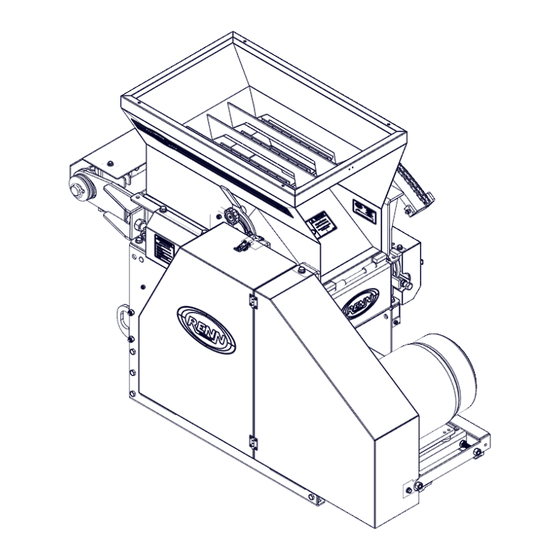
Page 31: Overall Dimensions
8 SPECIFICATIONS 8.3 Overall Dimensions Note: Motor not included. - 8.3 -... -
Page 32: Parts
9 PARTS 9.1 Top Hopper REF # PART # DECRIPTION 611200-0042.00 Grate Magnet - 12" RM (Large Grain) 611200-0606.00 Top Hopper Weldm't - 2020 170000-0180 Cotter Pin - 3/16" x 1" 611200-0025.00 Hinge Pin - 12" 411200-0521.00 Top Hopper - Grain Containment Belt 167200-0642 Nyloc Nut - 1/4"... - Page 33 9 PARTS 9.1 Top Hopper - 9.2 -...
- Page 34 9 PARTS 9.1.1 Top Hopper (Knob) REF # PART # DECRIPTION 168000-0049 Flat Washer - 3/8" USS PL 163000-0506 Carriage Bolt 3/8" NC x 3/4" Gr.5 PL 168000-0540 Flat Washer - 3/8" SAE 167200-0412 Lock Nut - 3/8" NC 140000-0224 Lock Knob 168600-0071 Lock Washer - 3/8"...
- Page 35 THIS PAGE INTENTIONALLY LEFT BLANK...
-
Page 36: Roller Mill - Upper Half
9 PARTS 9.2 Roller Mill - Upper Half REF # PART # DECRIPTION 611200-0519.00 Main Frame Insert 159400-0401 Hex Bolt - 1/2" NC x 1-1/2" Gr.5 PL 168600-0098 Lock Washer - 1/2" PL 168000-0544 Flat Washer - 1/2" SAE PLTD 614000-0182.04 Main Frame Insert 159600-0420... - Page 37 9 PARTS 9.2 Roller Mill - Upper Half - 9.5 -...
-
Page 38: Worm Drive Roll Adjustment
9 PARTS 9.3 Worm Drive Roll Adjustment REF # PART # DECRIPTION 159400-0427 Hex Bolt - 1/2" NC x 2" Gr.5 PL 615100-0219.00 Pull Plate - RH 168000-0544 Flat Washer - 1/2" SAE PLTD 167200-0688 Nyloc Nut - 1/2" NC Gr.5 PL 414000-0582.00 3/16"Keystock x 1-1/2"... - Page 39 9 PARTS 9.3 Worm Drive Roll Adjustment 167200-0652 Nyloc Nut - 3/8" NC Gr.5 PL 613000-0069.00 Clevis Weldment 414000-0239.00 Cam Pivot Pin - 1" x 2-1/2" 113500-0126 Oilite Bushing 1" x 1-1/4" x 1" - 9.7 -...
-
Page 40: Roll Drive - Front
9 PARTS 9.4 Roll Drive - Front REF # PART # DECRIPTION 144500-0850 V Belt - 5VX850 142800-0154 Pulley - 2 Groove 15.4" - B Bushing 141800-0031 B 1-15/16" Bushing 414000-0553.01 1/2" Keystock x 2-1/4" 154000-0140 Overcenter Latch - 4.7" 159300-0520 Stove Bolt - #10-24 x 1/2"... - Page 41 9 PARTS 9.4 Roll Drive - Front - 9.9 -...
-
Page 42: Roll Drive - Rear
9 PARTS 9.5 Roll Drive - Rear REF # PART # DECRIPTION 159600-0530 Hex Bolt - Full Thread - 5/8" NC x 3" Gr.5 PL 167000-0658 Jam Nut - 5/8" NC Gr.5 PL 614000-0505.01 Rear Belt Tensioner Weldment 144000-0664 V-Belt - BB60 414000-0812.01 Washer 114000-0098... - Page 43 9 PARTS 9.5 Roll Drive - Rear - 9.11 -...
-
Page 44: Pulley Tensioner
9 PARTS 9.6 Pulley Tensioner REF # PART # DECRIPTION 159400-0401 Hex Bolt - 1/2" NC x 1-1/2" Gr.5 PL 168000-0544 Flat Washer - 1/2" SAE PLTD 167200-0688 Nyloc Nut - 1/2" NC Gr.5 PL 412400-0532.02 Tensioner Bracket 163100-0120 Carriage Bolt - 1/2" NC x 6" Gr.5 BL 167000-0650 Jam Nut - 1/2"... - Page 45 9 PARTS 9.6 Pulley Tensioner - 9.13 -...
-
Page 46: Bottom Hopper & Auger
9 PARTS 9.7 Bottom Hopper & Auger REF # PART # DECRIPTION 612600-0268.00 Rear Panel Weldmt. - 8" X-Auger - 2018 167200-0652 Nyloc Nut - 3/8" NC Gr.5 PL 114000-0162 Flangette - 62mm 163000-0507 Carriage Bolt - 3/8" NC x 1" Gr.5 PL 167200-0648 Nyloc Nut - 5/16"... - Page 47 9 PARTS 9.7 Bottom Hopper & Auger - 9.15 -...
-
Page 48: Roll Bushing Assembly - B-Loc Bushing
9 PARTS 9.8 Roll Bushing Assembly - B-Loc Bushing [ #2 ] [ #1 ] [ #3 ] Tightening Roll Size B-Loc B-Loc Hub Socket Head Cap Screw Torque Dia. x Length Spacer Ring Part # & I/D (QTY) & Size (ft-lbs) &... - Page 49 Notes - 10.1 -...
- Page 50 Notes - 10.2 -...
- Page 51 Printed in Canada RENN MILL CENTER LP. RR#4, Lacombe, AB, T4L 2N4, Canada | P. 403.784.3518 | F 403.784.2060 | rennmill@rennmill.com | rennmill.com...
Need help?
Do you have a question about the RENN RMC-12 ELECTRIC and is the answer not in the manual?
Questions and answers