Table of Contents
Advertisement
Quick Links
Advertisement
Table of Contents

Related Manuals for Degelman R570P


Summary of Contents for Degelman R570P
- Page 1 OPERATOR & PARTS MANUAL 142636 v1.4 D E G E L M A N I N D U S T R I E S L T D. B O X 8 3 0 - 2 7 2 I N D U S T R I A L D R I V E , R E G I N A , S K ,...
-
Page 3: Table Of Contents
TABLE OF CONTENTS - OPERATORS SECTION Introduction Safety Overview Assembly Preparation Tractor Preparation Hook-up / Unhooking Pre-Operation Checklist Operation Transporting Storage / Safety Decals Service & Maintenance Service Intervals Adjustments / Repair 16-19 Troubleshooting PARTS SECTION Hitch Components Hopper, Grill, Mainframe Components Wheel Components Hydraulics and Cylinder Components Warranty... -
Page 5: Introduction
If you follow the instructions given in this manual, your machine will work well for many years. Safe, efficient and trouble free operation of your Degelman Rock Picker requires that you and anyone else who will be operating or maintaining the Rock Picker, read and understand the Safety, Operation, Maintenance and Troubleshooting information contained within this Manual. -
Page 6: Safety
Safety Why is SAFETY important to YOU? 3 BIG Reasons: •Accidents Can Disable and Kill •Accidents Are Costly •Accidents Can Be Avoided SAFETY ALERT SYMBOL The Safety Alert Symbol means: he Safety Alert Symbol identifies important safety messages applied to the Rock Picker and in this ATTENTION! manual. - Page 7 GENERAL SAFETY YOU are responsible for the safe operation and 1. Read and understand the Operator’s maintenance of your Degelman Rock Picker. YOU Manual and all safety signs before must ensure that you and anyone else who is going operating, maintaining or adjusting to operate, maintain or work around the Rock Picker the Rock Picker.
-
Page 8: Overview
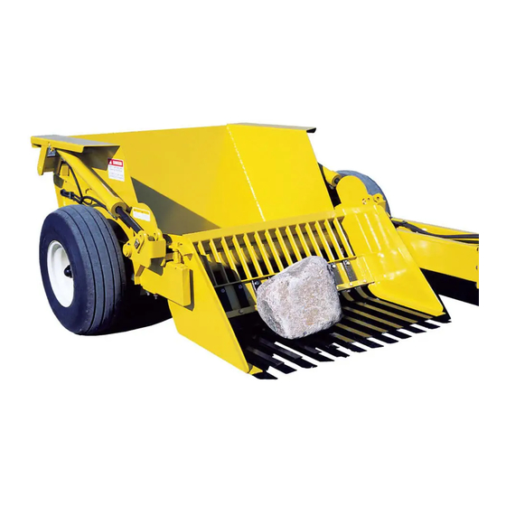
TO THE NEW OPERATOR OR OWNER PRINCIPLES OF OPERATION It is the owner’s or operator’s responsibility The Degelman Prong Type Rock Picker is a pull to read this manual carefully to learn how to behind machine, capable of spot picking and operate the machine safely and how to set it to boulder removal. -
Page 9: Assembly
Assembly ASSEMBLY PROCEDURE b) Using the 3/8” hose clamps, 5/16” As received, place the machine on level ground on x 2-1/2” bolt, 5/16” flat washers, lock top of two 4”x 4” wooden planks layed lengthwise. washers and nuts, secure hydraulic hoses in place and tighten. -
Page 10: Preparation
Preparation HOOK-UP / UNHOOKING TRACTOR PREPARATION Follow this procedure when selecting and preparing The Rock Picker should always be parked on a level, a tractor for use with the machine: dry area that is free of debris and foreign objects. 1. - Page 11 Preparation HITCH CLEVIS ADJUSTMENTS REMOVING THE TRANSPORT PINS Once the NOTE Make sure the rock picker tires have the hydraulic system specified air pressure (45 psi) before adjusting. of the rock picker is operable, raise The hitch pole should always be set to be parallel to the picker grill the ground when attached to the tractor.
-
Page 12: Pre-Operation Checklist
Preparation PRE-OPERATION CHECKLIST BREAK-IN IMPORTANT: Follow the pre-operational checklist IMPORTANT: It is extremely important to follow for both your personal safety and for maintaining the all of the Break-In procedures especially those listed proper mechanical condition of the machine. in the “Before using” section below to avoid damage: Before operating this machine, the following Although there are no operational restrictions on areas should be checked off:... -
Page 13: Operation
Operation OPERATOR’S RESPONSIBILITY GRILL DEPTH CONTROL STOP ADJUSTMENT Every operator should read this manual and be • Before attempting a final adjustment for the grill instructed in safe operating procedures. An untrained depth control stop, it is very important to set the operator is not qualified to operate this machine and hitch pole first, whether at the hitch pole clevis or at could place themselves or bystanders in danger. - Page 14 Operation FIELD OPERATIONS LOADING/DUMPING: Refer to these operational hints before starting: Loading: The machine can be loaded until the hopper box is filled but do not overfill. - Begin rock picking operations and observe the If hopper box is overfilled, rocks may roll machine’s performance regarding the particular forward and fall in between the frame when field conditions before attempting any adjustments.
-
Page 15: Transporting
Transporting TRANSPORTING TRANSPORT SAFETY Follow this procedure when preparing to transport: • Read and understand ALL the information in the Operator’s Manual regarding procedures and 1. Clear the area of bystanders, especially small SAFETY when operating the Rock Picker in the children, before converting into transport field/yard or on the road. -
Page 16: Storage / Safety Decals
142255 Decal, Danger - Keep Safe Distance 142256 Decal, Caution - Remove Transport Pin 142220 Decal, Warning - Do Not Exceed 142008 Decal, Degelman - 6 x 25-3/4 142556 Decal, Red Reflector - 2 x 9 142557 Decal, Amber Reflector - 2 x 9... -
Page 17: Service & Maintenance
Service & Maintenance MAINTENANCE SAFETY HYDRAULIC SAFETY • Review the Operator’s Manual and all safety 1. Always place all tractor hydraulic controls in items before working with, maintaining or neutral before dismounting. operating the Rock Picker. 2. Make sure that all components in the hydraulic •... - Page 18 Service & Maintenance TORQUE SPECIFICATIONS HARDWARE/HOSE SPECIFICATIONS TORQUE Unless otherwise stated: CHECKING BOLT TORQUE • Hardware - Hex, Plated GR5 UNC or P8.8 (metric) The tables shown below give correct • Hydraulic Hoses - 3/8 & 1/2, ends torque values for various bolts and come with 3/4 JIC female swivel.
-
Page 19: Service Intervals
Service & Maintenance SERVICE INTERVALS Due to the wide range of operational conditions that the machine will be subjected, it is difficult and rather complex to specify maintenance requirements for a given timing. Therefore, the following maintenance recommendations are to be only a guide. - Page 20 Service & Maintenance HYDRAULIC CYLINDER REPAIR 5. Take the plastic removal ring from the seal kit: PREPARATION Types of Cylinders a) Straighten the ring and remove any kinks or When cylinder repair (Wire Ring / Threaded Head) excessive curl to make installation easier and is required, clean off prevent it from falling out.
- Page 21 Service & Maintenance 8. Remove locknut, piston and head from rod. 11. b) Tighten the band clamp to ensure the wire ring is fully seated. Then, loosen the clamp Piston Seal (2pcs) approx. 1/2 a turn to allow band clamp to slide Wear Ring during fi nal assembly.
- Page 22 Service & Maintenance REPAIRING A THREADED HEAD CYLINDER REPAIRING A THREADED HEAD CYLINDER Set Screw Style Locking Ring Style Barrel Barrel Set Screw Locking Gland Ring Lock Piston U-Cup Wear Dual Seal Seal Piston Ring O-Rings Seal Wiper Piston Seals Seal (Style may vary, Lock...
- Page 23 Service & Maintenance WHEEL HUB REPAIR IMPORTANT Be sure to block up unit securely COMMON SPINDLE AND HUB COMPONENTS before removing tires. DISASSEMBLY 1. Carefully pry off dust cap. 2. Remove cotter pin from nut. Spindle 3. Remove nut and washer. 4.
- Page 24 Service & Maintenance REPLACING THE GRILL TINES GRILL SHAFT LOCKING COLLAR ADJUSTMENT • The locking collars located at both ends of the The grill tines (2) can be replaced with new ones. grill shaft should only be fitted snug, allowing the •...
- Page 25 Service & Maintenance GRILL DEPTH CONTROL STOP ADJUSTMENT CYLINDER ROD END / LIFT ARM SETTING • Before attempting a final adjustment for the grill depth control stop, it is very important to set the hitch pole first, whether at the hitch pole clevis or at the tractor drawbar, to get the hitch pole parallel to the ground level.
- Page 26 Troubleshooting TROUBLESHOOTING In the following section, we have listed some of the problems, causes and solutions that you may encounter. If you encounter a problem that is difficult to solve, even after having read through this troubleshooting section, please call your local dealer or distributor. Before you call, have this manual and the serial number from your unit ready.
- Page 28 Parts Section HITCH POLE COMPONENTS 118105 - Bolt, 5/16 x 2-1/2 (2) 143111 - Hose holder, Flexible (1) Long Pole - Standard 780279 - Top Plate, 3/8” (2) 118407 - Nut, 5/8” (1) Short Pole - Alternate/Previous 780278 - Hose Clamp, 3/8” (2) 118508 - Lock washer, 5/8”...
- Page 29 Parts Section HOPPER BOX & GRILL COMPONENTS 206000 - Hopper Box (1) 118028 - Bolt, 5/8 x 2-1/2 (10) 208150 - Tine Spacer Block (11) 208140 - Tine Holder Bar (1) 118030 - Bolt, 5/8 x 3 (11) 118537 - Flat Washer, 5/8 F436 (21) 118447 - Lock Nut, 5/8 GRC Unitorque (21)
- Page 30 Parts Section WHEEL COMPONENTS 131324 - Assembly, Hub/ Tire Pressure Spindle - 2 x 12 (2) 118643 - Bolt, 1/2 x 4 GR8 (2) 12.5L x15 -8 PLY: 45 PSI (310 kPa) 118587 - Flat Washer, 1/2 - F436 (4) 131329 - Tire Assembly (2) 118729 - Lock Nut, 1/2 GRC - Unitorque (2) 127007 - Tire, 12.5L x 15 - 8 PLY (1)
- Page 31 Hydraulic Components & Cylinders Required Hoses 126522 - Hose, 3/8 x 36 126547 - Hose, 3/8 x 42 126551 - Hose, 3/8 x 96 126516 - Hose, 3/8 x 106 (1) 126649 - Hose, 3/8 x 234 (2) 123062 - Cylinder, Monarch - 121945 - Pin, 1 x 5 (2) 3 x 31 x 1-1/2 - Pin Eyes (2) 118882 - Hair Pin,...
- Page 32 Re-torque of fastening hardware, Hydraulic fluid purities, drive train alignments, and clutch operation) 3. If parts not made or supplied by Degelman have been used in the connection with the unit, if, in the sole judgement of Degelman such use affects its performance, safety, stability or reliability.
- Page 33 It is the retail customer’s responsibility to deliver the product to the authorized Degelman dealer, from whom he purchased it, for service or replacement of defective parts, which are covered by warranty. Repairs to be submitted for warranty consideration must be made within forty-five days of failure.
Need help?
Do you have a question about the R570P and is the answer not in the manual?
Questions and answers