Table of Contents
Advertisement
Quick Links
OPERATOR & PARTS
MANUAL
143345 v1.2
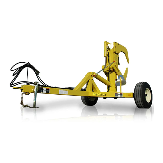
ROCK DIGGER
D E G E L M A N
I N D U S T R I E S
L T D.
B O X
8 3 0 - 2 7 2
I N D U S T R I A L
D R I V E ,
RD320
R E G I N A ,
S K ,
C A N A D A ,
S 4 P
3 B 1
F A X 3 0 6 . 5 4 3 . 2 1 4 0
P H 3 0 6 . 5 4 3 . 4 4 4 7
Serial Numbers above 1291
1 . 8 0 0 . 6 6 7 . 3 5 4 5
D E G E L M A N . C O M
Advertisement
Table of Contents

Related Manuals for Degelman ROCK DIGGER RD320


Summary of Contents for Degelman ROCK DIGGER RD320
- Page 1 OPERATOR & PARTS MANUAL 143345 v1.2 ROCK DIGGER D E G E L M A N I N D U S T R I E S L T D. B O X 8 3 0 - 2 7 2 I N D U S T R I A L D R I V E , RD320 R E G I N A ,...
-
Page 3: Table Of Contents
TABLE OF CONTENTS - OPERATORS SECTION Introduction Safety Overview Preparation 6 - 8 Operation Transporting Storage / Safety Decals Troubleshooting Service & Maintenance 13 - 21 TABLE OF CONTENTS - PARTS SECTION Overview Pole / Frame Components Rear Assembly Components Hydraulic Routing Hydraulic Cylinders Wheel Components... -
Page 5: Introduction
If you follow the instructions given in this manual, your machine will work well for many years. Safe, efficient and trouble free operation of your Degelman Rock Digger requires that you and anyone else who will be operating or maintaining the Digger, read and understand the Safety, Operation, Maintenance and Troubleshooting information contained within this Manual. -
Page 6: Safety
Safety Why is SAFETY important to YOU? 3 BIG Reasons: •Accidents Can Disable and Kill •Accidents Are Costly •Accidents Can Be Avoided SAFETY ALERT SYMBOL The Safety Alert Symbol means: he Safety Alert Symbol identifies important safety messages applied to the Rock Digger and in this ATTENTION! manual. - Page 7 GENERAL SAFETY YOU are responsible for the safe operation and 1. Read and understand the Operator’s maintenance of your Degelman Rock Digger. Manual and all safety signs before YOU must ensure that you and anyone else who operating, maintaining or adjusting is going to operate, maintain or work around the the Digger.
- Page 8 143345 - RockDigger 320 (17-August-2017)
-
Page 9: Overview
Overview TO THE NEW OPERATOR OR OWNER PRINCIPLES OF OPERATION The Degelman Rock Digger is designed to The Rock Digger consists of a hitch pole/frame unit, efficiently dig out large buried rocks and debris a rear arm/tooth assembly, a hooking arm frame from fields. -
Page 10: Preparation
Preparation OPERATING SAFETY BREAK-IN Although there are no operational restrictions on 1. Read and understand the Operator’s Manual the Rock Digger when it is new, there are some and all safety signs before using. mechanical checks that must be done to ensure the long term integrity of the unit. - Page 11 Preparation PRE-OPERATION CHECKLIST TRACTOR PREPARATION Efficient and safe operation of the Rock Follow this procedure when selecting and preparing Digger requires that each operator reads and a tractor for use with the machine: understands the operating procedures and all related safety procedures outlined in this 1.
- Page 12 Preparation ATTACHING / UNHOOKING The Rock Picker should always be parked on a level, dry area that is free of debris and foreign objects. Connect Hydraulics Follow this procedure when attaching: 1. Clear the area of bystanders and remove foreign objects from the machine and working area.
-
Page 13: Operation
Operation OPERATING 1. Operator’s Responsibility: 2) The second method disturbs less soil but requires working both hydraulic circuits Every operator should read this manual and simultaneously in an attempt to grab the rock be instructed in safe operating procedures. An between the rear teeth and the hook arm. -
Page 14: Transporting
Transporting TRANSPORTING TRANSPORT SAFETY Follow this procedure when preparing to transport: • Always travel at a safe speed. Use caution when making corners or meeting traffic. 1. Clear the area of bystanders, especially small children, before converting into transport • Make sure the SMV (Slow Moving Vehicle) configuration. -
Page 15: Storage / Safety Decals
142383 Decal, Caution - 6 Point Safety dirt, mud, debris or residue. 2. Inspect all moving parts to see if anything 142009 Decal, Degelman - 3-3/4” x 16-1/4” has become entangled in them. Remove the 142557 Reflector Tape - Amber, 2” x 9”... -
Page 16: Troubleshooting
Troubleshooting TROUBLESHOOTING In the following section, we have listed some of the problems, causes and solutions that you may encounter. If you encounter a problem that is difficult to solve, even after having read through this troubleshooting section, please call your local dealer or distributor. Before you call, have this manual and the serial number from your unit ready. -
Page 17: Service & Maintenance
Service & Maintenance MAINTENANCE SAFETY HYDRAULIC SAFETY • Review the Operator’s Manual and all safety 1. Always place all tractor hydraulic controls in items before working with, maintaining or neutral before dismounting. operating the Rock Picker. 2. Make sure that all components in the hydraulic •... - Page 18 Service & Maintenance HARDWARE/HOSE SPECIFICATIONS TORQUE SPECIFICATIONS Unless otherwise stated: CHECKING BOLT TORQUE • Hardware - Hex, Plated GR5 UNC or P8.8 (metric) The tables shown below give correct torque values • Hydraulic Hoses - 3/8 & 1/2, ends come with for various bolts and capscrews.
- Page 19 Service & Maintenance FLUIDS AND LUBRICANTS SERVICE INTERVALS 1. Grease: Use an SAE multi-purpose 25 Hrs. grease with extreme pressure (EP) performance. Also acceptable is an Grease Hook Arm Bearings - 2 locations SAE multi-purpose lithium base grease. (nipple located on top of cast bearing housing) 2.
- Page 20 2. Loosen jam nut/eye bolt combination. NOTE: Special hard surfacing rod kits are available 3. Attach chain to hole in rear arm. through Degelman Industries Ltd. or your local Degelman dealer. 4. Start tightening the chain by turning the lower jam nut on the chain until there is a slight amount of slack.
- Page 21 Service & Maintenance WHEEL HUB REPAIR IMPORTANT Be sure to block up frame section COMMON SPINDLE AND HUB COMPONENTS securely before removing tires. DISASSEMBLY 1. Carefully pry off dust cap. 2. Remove cotter pin from nut. Spindle 3. Remove nut and washer. 4.
- Page 22 Service & Maintenance HYDRAULIC CYLINDER REPAIR 5. Take the plastic removal ring from the seal kit: PREPARATION Types of Cylinders a) Straighten the ring and remove any kinks or When cylinder repair (Wire Ring / Threaded Head) excessive curl to make installation easier and is required, clean off prevent it from falling out.
- Page 23 Service & Maintenance 8. Remove locknut, piston and head from rod. 11. b) Tighten the band clamp to ensure the wire ring is fully seated. Then, loosen the clamp Piston Seal (2pcs) approx. 1/2 a turn to allow band clamp to slide Wear Ring during fi nal assembly.
- Page 24 Service & Maintenance REPAIRING A THREADED HEAD CYLINDER REPAIRING A THREADED HEAD CYLINDER Set Screw Style Locking Ring Style Barrel Barrel Set Screw Locking Gland Ring Lock Piston U-Cup Wear Dual Seal Seal Piston Ring O-Rings Seal Wiper Piston Seals Seal (Style may vary, Lock...
- Page 25 Service & Maintenance SPECIFICATIONS MODEL - Rock Digger RD320 WHEEL/HUBS: - Two 12.5 L x 15-S ply tubeless type tires MACHINE WEIGHT: - 2400 lbs. (1090 kg) - 6 bolt rim TRACTOR REQUIREMENTS: - Heavy duty hubs - greaseable - 100 horsepower (75 kW) minimum...
- Page 27 Parts Section TABLE OF CONTENTS - PARTS SECTION IMPORTANT: Overview Pole/Frame Components READ MANUAL Rear Assembly Components Hydraulic Routing Hydraulic Cylinders Wheel Components Warranty 27-28 Rear Assembly Components Hook Arm Cylinder Lock-Up Chain Rear Arm Cylinder Wheel Components Rear Frame Pin Pole/Frame Components Jack...
- Page 28 118407 - Nut, 5/8” (1) 118508 - Lock washer, 5/8” (1) 118514 - Flat washer, 5/8” (1) 142009 - Decal, 142380 - 142557 - Degelman - 3-3/4 Decal, Warning Reflector, Amber x 16-1/4 (2) -Falling Arm (2) - 2” x 9” (2)
- Page 29 110042 - Casting, Bearing - Cap (2) 118775 - Flat washer, 3/4” SAE (4) 110040 - Casting, Bearing - Base (2) 110051 - Shim, 16 Ga. (4) 142009 - Decal, Degelman - 3-3/4 x 16-1/4 (2) 142381 - Decal, Warning -Falling Hook Hazard (2) 242037 - Pin, 2-1/16 x 22-1/2”...
- Page 30 Hydraulic Routing Hook Arm Hydraulic Cylinders Cylinder 123195 - Cylinder, Hook Arm - 3 x 16 x 1-1/2 (1) (Previous)122729 - Cylinder, Hook Arm (2) PORTS FACE 123203 - Cylinder, Rear Arm - 5 x 24 x 2-1/2 (1) DOWN (Previous)122240 - Cylinder, Rear Arm (2) Required Hoses 126504 - Hose, 3/8 x 32...
- Page 31 Hydraulic Cylinders REAR ARM CYLINDER 123203 - Cylinder, Monarch - 5” x 24” x 2-1/2” (1) PREVIOUS 2-1/2”: 122240 - Cylinder, Rear Arm - 5” x 24” x 2-1/2” 122825 - Piston (1) 122822 - Barrel (1) 118946 - Lock Nut, 122821 - Lock 1-1/4 - UNF 123204 - Seal Kit...
- Page 32 Wheel & Hub Components WHEEL COMPONENTS (Left Side Shown) 118126 - Bolt, 1/2”x 4” (2) 131329 - Wheel Assembly, 118420 - Lock 12.5L-15-8 Ply (2) Nut, 1/2” (2) comes with... 127007 - Tire, 12.5L-15-8 Ply (1) 131324 - Hub/Spindle 131328 - Rim, 15 - 6 Bolt (1) Assembly (2) 127006 - Valve, Stem TR415 (1) Tire Pressure...
- Page 33 It is the retail customer’s responsibility to deliver the product to the authorized Degelman dealer, from whom he purchased it, for service or replacement of defective parts, which are covered by warranty. Repairs to be submitted for warranty consideration must be made within forty-five days of failure.
- Page 34 Re-torque of fastening hardware, Hydraulic fluid purities, drive train alignments, and clutch operation) 3. If parts not made or supplied by Degelman have been used in the connection with the unit, if, in the sole judgement of Degelman such use affects its performance, safety, stability or reliability.
Need help?
Do you have a question about the ROCK DIGGER RD320 and is the answer not in the manual?
Questions and answers