Table of Contents
Advertisement
Quick Links
Stroke Reading Cylinder and Counter
CE
Series
CEP1/CEU5
Resolution: 0.01 mm (Accuracy ± 0.02 mm)
Output function: RS-232C BCD
Output: 5 points (Bank switching: 20 points)
31 points (Binary output)
High Precision Stroke
Reading Cylinder
CEP1
Series
ø12, ø20
P.647
Stroke Reading
Cylinder
CE1
Series
ø12, ø20, ø32, ø40
ø50, ø63
P.656
Multi-counter
CEU5
Series
P.667
CEP1
CEP1
CE1
CE1
CE2
ML2B
D-
-X
641
Advertisement
Table of Contents

Related Manuals for SMC Networks CE Series


Summary of Contents for SMC Networks CE Series
- Page 1 Stroke Reading Cylinder and Counter Series CEP1 CEP1 CEP1/CEU5 Resolution: 0.01 mm (Accuracy ± 0.02 mm) ML2B Output function: RS-232C BCD Output: 5 points (Bank switching: 20 points) 31 points (Binary output) High Precision Stroke Stroke Reading Multi-counter Reading Cylinder Cylinder CEU5 Series...
- Page 2 Air Cylinder with Measurement Function/Stroke Reading Cylinder CE Series Counter CEU Series Measurement is possible throughout the full stroke range. The home position can be anywhere When the counter is reset by pressing within the cylinder stroke. the cylinder rod to the reference plane, that point becomes the home position.
-
Page 3: Simple Operation
Achieve rationalization of production lines Stroke reading cylinder with position feedback Tolerances of preset values can be set. CEP1 CEP1 Tolerances can be set for preset values. + set tolerance, – set tolerance (separate settings) ML2B Simple operation Multi-counter (CEU5) DC12V GND F.G. - Page 4 Series Application Examples Parts inspection Confirmation of press-in Can confirm the press-in of a Measures the dimensions of hydraulic cylinder by detecting its parts, discriminates between stroke. good and defective articles, Even if the size of the workpiece and prevents the mingling of changes, the point of press-in different parts, etc.
-
Page 5: Measurement Principle
Series Stroke Reading Cylinder Measurement Principle A/B Phase Difference Output (90° phase difference output) The amount of rod movement in the stroke reading cylinder is When movement is expressed by a single line of pulses, it is detected using an MR element (magnetic resistance element) impossible to accurately identify the current position, because whose resistance value changes due to magnetic force. -
Page 6: Specific Product Precautions
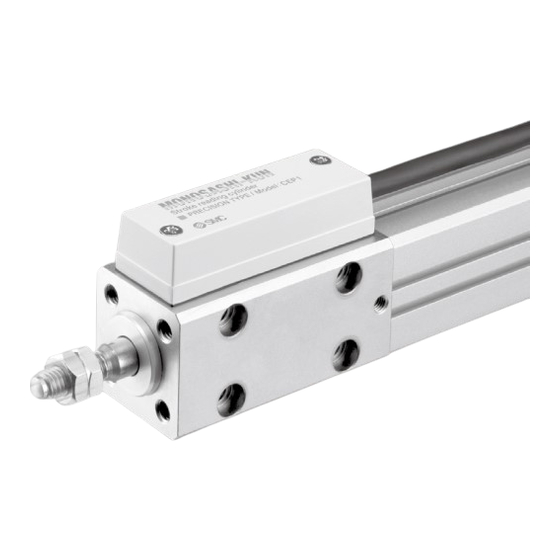
Series Specific Product Precautions Be sure to read this before handling the products. Refer to back page 50 for Safety Instructions and pages 3 to 12 for Actuator and Auto Switch Precautions. Caution Caution Operating Environment Effects of Noise Use in an environment where liquid (water, oil, coolant, etc.) When the stroke reading cylinder is used near a motor, welding splashes on the product may result in a malfunction;... - Page 7 High Precision Stroke Reading Cylinder Non-rotating Piston Type CEP1 Series Note) RoHS Note) CE-compliant: When connecting ø12, ø20 to a multi-counter (CEU5-D, power supply voltage 24 VDC). Refer to the multi-counter operation manual for details. CEP1 CEP1 How to Order M9BW CEP1 ML2B...
-
Page 8: Cylinder Specifications
CEP1 Series Cylinder Specifications Action Double acting, Single rod (Non-rotating piston) Fluid Proof pressure 1.5 MPa Maximum operating pressure 1.0 MPa ø12 ø20 Minimum operating pressure 0.15 MPa 0.1 MPa Piston speed 50 to 300 mm/s Ambient and fluid temperature 0 to 60°C (No freezing) Lubrication Non-lube... -
Page 9: Mounting Bracket
CEP1 High Precision Stroke Reading Cylinder Series Non-rotating Piston Type Weight (Sensor cable length 0.5 m, With connector, Without mounting bracket (both ends tapped)) Auto Switch Proper Mounting Position (kg) Regarding dimensions for the auto switch proper Cylinder stroke (mm) Bore size mounting position (at stroke end), refer to page 655. -
Page 10: Component Parts
CEP1 Series Construction ø12, ø 20 Component Parts Component Parts Note Note Description Material Description Material Cylinder tube Magnet Aluminum alloy Hard anodized — Rod cover Cross recessed countersunk head screw Aluminum alloy Hard chrome plated Chromium molybdenum steel Chromated Head cover Aluminum alloy Hard anodized... - Page 11 CEP1 High Precision Stroke Reading Cylinder Series Non-rotating Piston Type Dimensions: ø12 Direct mounting, rod side tapped type: CEP1B12 Stroke CEP1 CEP1 Cable end + 0.05 ø4 depth 4 + 0.02 (Positioning pin hole) ML2B 4 x M5 x 0.8 Thread depth 10 Metal connector M14 x 1...
- Page 12 CEP1 Series Dimensions: ø12 Foot type: CEP1L12 Stroke 4 x ø4.5 Rod side flange type: CEP1F12 Stroke ø4 + 0.05 + 0.02 (Positioning pin hole) 4 x ø4.5...
- Page 13 CEP1 High Precision Stroke Reading Cylinder Series Non-rotating Piston Type Dimensions: ø20 Direct mounting, rod side tapped type: CEP1B20 Stroke CEP1 CEP1 Cable end + 0.05 ø4 depth 4 + 0.02 (Positioning pin hole) ML2B 4 x M6 x 1.0 Thread depth 12 Metal connector M14 x 1...
- Page 14 CEP1 Series Dimensions: ø20 4 x ø5.5 Foot type: CEP1L20 Stroke 13.5 Rod side flange type: CEP1F20 Stroke ø4 + 0.05 + 0.02 (Positioning pin hole) 4 x ø5.5...
-
Page 15: Operating Range
CEP1 Series Auto Switch Mounting Auto Switch Proper Mounting Position (Detection at Stroke End) Operating Range (mm) Auto switch Bore size CEP1 CEP1 Auto switch model D-A9/A9V D-M9/M9V D-M9W/M9WV D-M9A/M9AV ∗ Since the operating range is provided as a guideline ML2B including hysteresis, it cannot be guaranteed (assuming approximately ±30% dispersion). - Page 16 Note) Stroke Reading Cylinder Note) CE-compliant: When connecting to a multi-counter (CEU5-D, Series power supply voltage 24 VDC). Refer to the counter operation manual for details. RoHS ø12, ø20, ø32, ø40, ø50, ø63 How to Order M9BW Number of Mounting type auto switches Auto switch Bore size...
- Page 17 Series Stroke Reading Cylinder Cylinder Specifications Fluid Proof pressure 1.5 MPa Maximum operating pressure 1.0 MPa ø12 ø20 to ø63 Minimum operating pressure CEP1 0.07 MPa 0.05 MPa Piston speed 70 to 500 mm/s Ambient and fluid temperature 0 to 60°C (No freezing) Humidity 25 to 85% RH (No condensation) Lubrication...
- Page 18 Series Auto Switch Proper Mounting Position Weight (Sensor cable length 0.5 m, With connector, Without mounting bracket (both ends tapped)) (kg) Regarding dimensions for the auto switch proper Cylinder stroke (mm) Bore size mounting position (at stroke end), refer to page 665. (mm) 0.28 0.32...
- Page 19 Series Stroke Reading Cylinder Construction ø ø ø @7 @4 @ 8 @0 o i @3 !0 u @8 @4 !2 r e @4 @8 i @3 @4 @8 @7 @2 r CEP1 !9 #0 w #1 #0 t q #1 @1 !9 t @5 @6 q !1 w #1 #0 @2 @9 #1 @1...
- Page 20 Series Dimensions: ø12, ø20 Both ends tapped type: CE1B Bore size Stroke 2 x P (Port size) 2 x øN through 500 or 3000 4 x O thread depth R Metal connector M14 x 1 B + Stroke A + Stroke (mm) Bore size (mm) Standard stroke...
- Page 21 Series Stroke Reading Cylinder Foot type: CE1L Bore size Stroke 4 x O (Special cap bolt) CEP1 4 x øLD LS + Stroke A + Stroke ML2B Rod side flange type: CE1F Bore size Stroke 2 x øFD 2 x O (Special cap bolt) Head side flange type: CE1G...
- Page 22 Series Dimensions: ø32, ø40, ø50, ø63 Both ends tapped type: CE1B Bore size Stroke 4 x øN through 8 x O thread depth 20 500 or 3000 B + Stroke A + Stroke 2 x P (Port size) Metal connector M14 x 1 (mm) Bore size (mm)
- Page 23 Series Stroke Reading Cylinder Foot type: CE1L Bore size Stroke CEP1 4 x O LS + Stroke 4 x øLD (Special cap bolt) A + Stroke ML2B Rod side flange type: CE1F Bore size Stroke 4 x øFD 4 x O A + Stroke (Special cap bolt) Head side flange type:...
- Page 24 Series Auto Switch Mounting Auto Switch Proper Mounting Position (Detection at Stroke End) and Its Mounting Height D-A9 D-A9V D-M9 D-M9V D-M9W D-M9WV D-M9A D-M9AV ø12 to ø20 ≅ U ø 32 to ø 63 D-A9 D-A9V D-M9 D-M9V D-M9W D-M9WV D-M9A D-M9AV...
- Page 25 Series Auto Switch Mounting Auto Switch Proper Mounting Position (Detection at Stroke End) and Its Mounting Height Auto Switch Proper Mounting Position (mm) Auto switch D-M9 D-A72/A7H/A80H model D-M9V D-A73C/A80C/F7 D-A9 D-M9W D-A73 D-F79F/J79/F7V D-F7NT D-A79W D-A9V D-M9WV D-A80 D-J79C/F7W D-M9A D-J79W/F7WV CEP1...
- Page 26 Series Auto Switch Mounting Bracket: Part No. Auto switch Bore size (mm) mounting ø12, ø20 ø32, ø40, ø50, ø63 surface Port side Auto Auto switch mounting surface Auto switch mounting surface Note 1) When a compact auto switch is switch mounted on the three sides (A, model Auto switch mounting rail side only...
-
Page 27: Connection Method
Note) Series Series Note) CE-compliant: When connecting to a Counter/Extension Cable stroke reading cylinder (CE1), a high precision stroke reading cylinder (CEP1) and a stroke reading cylinder with brake (CE2). (CEU5-D type) Refer to the operation manual for details. RoHS ... - Page 28 Series Multi-counter/Specifications CEU5 CEU5-D CEU5P CEU5P-D CEU5B CEU5B-D CEU5PB CEU5PB-D Model Type Multi-counter Mounting Surface mounting (DIN rail or Screw stop) Operating system Adding - subtracting type Operation mode Operating mode, Data setting mode, Function setting mode Reset system External reset terminal Display system LCD (With back light) Number of digits...
-
Page 29: Extension Cable
Series Counter Wiring with External Equipment <Wiring with multi-counter CEU5> 3. Output circuit 1. Wiring of power source for driving counter There are two outputs, the NPN open collector and the PNP open collector. For power source for driving counter, use the one The maximum rating is 30 VDC, 50 mA. - Page 30 Series Operating Condition of each Output Mode One-shot Output Without allowable values With allowable values When the counter value passes the preset value, output is When the counter value passes the sum of the preset turned ON for 100 ms. value + the allowed value, output is turned ON for 100 ms.
- Page 31 CEP1 ML2B D- -X...
-
Page 32: Parts Description
Series CEU5 Operation External Parts description power Pulse input supply Control signal input terminals 12 VDC GND F.G. R.S. HOLD BANK1 BANK2 MULTI COUNTER : CEU5 BCD Output (Refer to page 676.) Display PRESET COUNT FUNC. connector LEFT RIGHT (on side) DOWN SEL. - Page 33 Series Counter Mode cycle using mode key Basic Operation • SET key : In any of the conditions (1) through (5), this writes the display data into the memory and shifts to (1). • SEL. key : Shifts to the next item, but does not write data. CEP1 •...
- Page 34 Series CEU5 Operation 3. Explanation of settings in the function mode If the UP/DOWN keys are pressed when an item name is flashing , it shifts to another setting item. When the SEL. key is pressed, the cursor shifts and it is possible to change the content of the setting for the item which is being displayed. Item name •...
-
Page 35: Output Type
Series Counter DOWN FUNC. FUNC. SEL. key Output type CEP1 • The output system setting mode is selected by • Select normal output or binary output with the pressing the SEL. key while OUTPUT is flashing. UP/DOWN keys. • Store the setting with the SET key. •... -
Page 36: Bank Function
Series Glossary (Functions of CEU5) BCD Output Bank Function This is a system which expresses one digit of a decimal number 5 points of preset output are possible simultaneously, however, a with a 4 digit binary number. maximum of 20 types of work discrimination, etc. can be performed by using the 5 points of preset values as one of a The count value is expressed by the ON/OFF state of each BCD output terminal. - Page 37 Series Glossary Display Offset Function Count Value Protection Normally the count value returns to “0” after resetting, but with this In the past, the count value returned to “0” when the power supply CEP1 function, the initial value can be set to any desired value. was cut off, but this function holds the previous value even after a power failure.
Need help?
Do you have a question about the CE Series and is the answer not in the manual?
Questions and answers