Advertisement
Quick Links
CXS M
Bearing type
M
Slide bearing
Ball bushing bearing
L
Bore size/Stroke (mm)
Bore size
Standard stroke (mm)
6
10, 20, 30, 40, 50
10, 15, 20, 25, 30, 35, 40, 45,
10
50, 60, 70, 75
15, 20
10, 15, 20, 25, 30, 35, 40, 45,
25, 32
50, 60, 70, 75, 80, 90, 100
Applicable Auto Switches
Electrical
Type
Special function
—
Grommet
Diagnostic indication
(2-color indication)
Water resistant
(2-color indication)
Grommet
—
Water resistant type auto switches can be mounted on the above models, but in such case SMC cannot guarantee water resistance.
Consult with SMC regarding water resistant types with the above model numbers.
Lead wire length symbols: 0.5 m ·········· Nil
3 m ·········· L
5 m ·········· Z
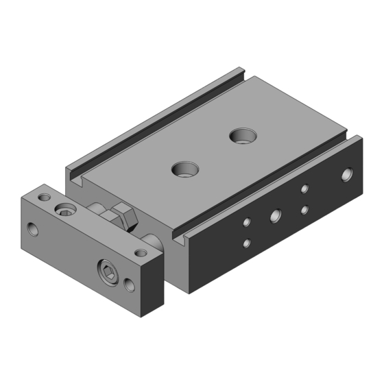
Dual Rod Cylinder
Basic Type
Series
ø6, ø10, ø15, ø20, ø25, ø32
How to Order
Thread type
Symbol
Nil
TN
TF
20
100
/Refer to pages 1893 to 2007 for further information on auto switches.
Load voltage
Wiring
(Output)
entry
DC
3-wire (NPN)
5 V, 12 V
3-wire (PNP)
12 V
2-wire
3-wire (NPN)
24 V
5 V, 12 V
3-wire (PNP)
2-wire
12 V
3-wire
—
(NPN equivalent)
24 V
12 V
2-wire
None
(Example) Y59A
(Example) Y59AL
(Example) Y59AZ
CXS
Type
Bore size
M thread
ø6 to ø20
Rc 1/8
NPT 1/8
ø25,ø32
G 1/8
Y7BW
Auto switch
Nil
Without auto switch (Built-in magnet)
For the applicable auto switch model, refer to the table below.
Auto switch model
AC
Perpendicular
In-line
Y69A
Y59A
Y7P
Y7PV
Y69B
Y59B
Y7NWV
Y7NW
—
Y7PWV
Y7PW
Y7BWV
Y7BW
—
Y7BA
5 V
—
—
Z76
—
100 V
Z73
—
100 V or less
Z80
Solid state auto switches marked with " " are produced upon receipt of order.
Made to Order
Refer to page 666 for details.
Number of auto switches
Nil
2 pcs.
S
1 pc.
n
"n" pcs.
Lead wire length (m)
Pre-wired
Applicable load
0.5
3
5
connector
(Nil)
(L)
(Z)
circuit
circuit
—
—
—
circuit
—
—
—
IC circuit
IC
—
Relay,
IC
PLC
—
CX2
IC
—
CXW
—
Relay,
PLC
CXT
CXSJ
CXS
CXS
D-
-X
665
Advertisement

Related Manuals for SMC Networks CXS Series


Summary of Contents for SMC Networks CXS Series
- Page 1 Dual Rod Cylinder Basic Type Series ø6, ø10, ø15, ø20, ø25, ø32 How to Order Thread type Symbol Type Bore size M thread ø6 to ø20 Rc 1/8 NPT 1/8 ø25,ø32 G 1/8 CXS M Y7BW Made to Order Refer to page 666 for details. Bearing type Slide bearing Number of auto switches...
-
Page 2: Specifications
Series Specifications Bore size (mm) Fluid Air (Non-lube) Proof pressure 1.05 MPa Maximum operating pressure 0.7 MPa Minimum operating pressure 0.15 MPa 0.1 MPa 0.05 MPa Ambient and fluid temperature –10 to 60 C (No freezing) 30 to 700 mm/s 30 to 600 mm/s Piston speed 30 to 300 mm/s... -
Page 3: Operating Conditions
Dual Rod Cylinder Series Basic Type Operating Conditions Clean Series There are two types of cylinders, relieving type and vacuum type, available for a clean Non-rotating Accuracy room environment. The relieving type specification with the double-seal construction of the Non-rotating accuracy at the retracted end and rod section allows the cylinder to channel exhaust through the relief port directly to the without a load should be less than or equal to the value... - Page 4 Series Construction: Slide Bearing CXSM6 CXSM10 to 32 CXSM20 to 32 Component Parts Component Parts Description Material Note Description Material Note Bumper Polyurethane Housing Aluminum alloy Hard anodized Plug Chromium steel Nickel plated Piston rod A Carbon steel Hard chrome plated Piston seal Piston rod B Carbon steel...
- Page 5 Dual Rod Cylinder Series Basic Type Construction: Ball Bushing Bearing CXSL6 CXSL10 to 32 CXSL20 to 32 Component Parts: Standard Piping Component Parts Description Material Note Description Material Note Housing Aluminum alloy Hard anodized Ball bushing — Piston rod A Special steel Hard chrome plated Bearing spacer...
- Page 6 Series Dimensions: ø6 (58.5 + ST) (45 + ST) (10 + 1/2ST) 2.75 2 x ø3.4 through 2 x ø6.5 counterbore depth 3.3 2 x M5 x 0.8 thread depth 4.5 (Piping port) IN 2 x M3 x 0.5 2 x M3 x 0.5 (Through-hole) (Through-hole) 2 x M3 x 0.5 thread depth 4.5...
- Page 7 Dual Rod Cylinder Series Basic Type Dimensions: ø10, ø15 Stroke (Through-hole) (Opposite side: Same) 2 x 2 x M5 x 0.8 thread depth 4.5 (Piping port) (Opposite side: Same) (mm) Model 2 x ø3.4 through 2 x M3 x 0.5 2 x M4 x 0.7 4 x M3 x 0.5 CXS 10...
- Page 8 Series Dimensions: ø20, ø25, ø32 Stroke (Through-hole) (Opposite side: Same) (Piping port) (Opposite side: Same) (mm) Model 2 x ø5.5 through 2 x M4 x 0.7 CXS 20 11.5 ø10 2 x M5 x 0.8 2 x ø9.5 counterbore depth 5.3 thread depth 6 2 x ø6.9 through 2 x M5 x 0.8...
- Page 9 Series Auto Switch Mounting Auto Switch Proper Mounting Position (Detection at Stroke End) Electrical entry direction: Electrical entry direction: Inward Outward Operating Range D-Z7/Z8, D-Y7 W D-Y6 , D-Y7 V D-Y7BA Bore size D-Y5 , D-Y7 D-Y7 WV (mm) Bore size (mm) Auto switch model –5.5 15.5...
- Page 10 Series Made to Order: Individual Specifications Please contact SMC for detailed dimensions, specifications, and lead times. Symbol -X593 Without Plate X593 Bore size Stroke Auto switch Without plate This specification is for the cylinder without a plate. This cylinder is suitable for mounting your own plate. Please note that the rod end dimensions of this cylinder are different from those of the standard cylinder.
-
Page 11: Specific Product Precautions
Series Specific Product Precautions Be sure to read before handling. Refer to front matter 39 for Safety Instructions and pages 3 to 12 for Actuator and Auto Switch Precautions. Mounting Stroke Adjustment Caution Caution 3. A bumper at the end of the bumper bolt is replaceable. 1. -
Page 12: How To Order
Dual Rod Cylinder With Air Cushion Series ø20, ø25, ø32 How to Order Thread type Symbol Type Bore size ø20 M thread ø25, ø32 CXS M 100 A Y7BW Number of auto switches Dual Rod Cylinder (No. of auto switch) 2 pcs. - Page 13 Dual Rod Cylinder Series With Air Cushion Specifications Bore size (mm) Fluid Air (Non-lube) Precautions Proof pressure 1.05 MPa Maximum operating pressure 0.7 MPa Be sure to read before handling. Minimum operating pressure 0.1 MPa Refer to front matter 39 for Safety Ambient and fluid temperature –10 to 60 C (No freezing) Instructions and pages 3 to 12 for...
- Page 14 Series Construction CXSM/With air cushion CXSL/With air cushion Close-up of A Close-up of A Component Parts: CXSM Component Parts: CXSL Description Material Note Description Material Note Aluminum alloy Hard anodized Aluminum alloy Hard anodized Housing Housing Carbon steel Hard chrome plated Piston rod A Special steel Hard chrome plated...
- Page 15 Dual Rod Cylinder Series With Air Cushion Dimensions: ø20 53.5 2 x cushion needle 2 x M5 x 0.8 thread depth 4.5 (Piping port) (Steel ball) 2 x ø5.5 through 2 x M4 x 0.7 11.5 2 x ø9.5 counterbore depth 5.3 thread depth 6 2 x M5 x 0.8 (Through-hole)
- Page 16 Series Dimensions: ø25 57.5 45.5 2 x cushion needle Note) 2 x Rc 1/8 thread depth 6.5 (Piping port) (Steel ball) 2 x ø6.9 through 2 x M5 x 0.8 thread depth 7.5 2 x ø11 counterbore depth 6.3 2 x M6 x 1.0 (Through-hole) 4 x M5 x 0.8 thread depth 7.5 2 x M5 x 0.8 (30)
- Page 17 Dual Rod Cylinder Series With Air Cushion Dimensions: ø32 67.5 23.5 2 x cushion needle Note) 2 x Rc 1/8 thread depth 6.5 (Piping port) 16 14 (Steel ball) 2 x ø6.9 through 2 x M5 x 0.8 2 x ø11 counterbore depth 6.3 thread depth 8 2 x M6 x 1.0 (Through-hole)
- Page 18 Series Auto Switch Mounting Auto Switch Proper Mounting Position (Detection at Stroke End) Electrical entry direction: Inward Electrical entry direction: Outward D-Z7/Z8, D-Y7 W D-Y6 , D-Y7 V D-Y7BA Bore size D-Y5 , D-Y7 D-Y7 WV (mm) 40.5 36.5(35) 2.5(1) 38.5 30.5 –3.5...
- Page 19 Dual Rod Cylinder With End Lock for Retraction Side Series ø6, ø10, ø15, ø20, ø25, ø32 How to Order Thread type Symbol Type Bore size M thread Rc 1/8 ø25, ø32 NPT 1/8 G 1/8 CXS M 50 R Y7BW Number of auto switches 2 pcs.
- Page 20 Series Specifications Bore size (mm) Air (Non-lube) Fluid 1.05 MPa Proof pressure Maximum operating pressure 0.7 MPa Minimum operating pressure 0.3 MPa –10 to 60 C (No freezing) Ambient and fluid temperature Piston speed 30 to 300mm/s 30 to 800mm/s 30 to 700mm/s 30 to 600mm/s Cushion...
- Page 21 Dual Rod Cylinder Series With End Lock for Retraction Side Construction: Slide Bearing CXSM6 Component Parts Description Material Note Housing Aluminum alloy Hard anodized Piston rod B Carbon steel Hard chrome plated O-ring Lock rod Special steel Retaining ring Special steel Lock holder Aluminum alloy Lock pin...
- Page 22 Series Dimensions: ø6, ø10, ø15 CXS 6- R Manual lever insertion (mm) ø1.7 Model CXS 6-10R 88.5 CXS 6-20R 98.5 CXS 6-30R 108.5 CXS 6-40R 118.5 28.5 Hexagon (Width across flats 10) CXS 6-50R 128.5 Dimensions other than those listed above are the same as for the standard type.
- Page 23 Dual Rod Cylinder Series With End Lock for Retraction Side Dimensions: ø ø ø Manual lever insertion ø1.7 Hexagon ( (mm) Model CXS 20- R Width across flats13 CXS 25- R Width across flats16 CXS 32- R Width across flats19 (mm) Symbol Model...
- Page 24 Series Auto Switch Mounting Auto Switch Proper Mounting Position (Detection at Stroke End) Electrical entry direction: Outward Electrical entry direction: Inward D-Z7/Z8, D-Y7 W D-Y6 , D-Y7 V D-Y7BAL Bore size D-Y5 , D-Y7 D-Y7 WV (mm) 15.5 24.5 11.5 (10) 20.5 (19) 14.5 22.5...
- Page 25 Series With End Lock for Retraction Side Specific Product Precautions Be sure to read before handling. Refer to front matter 39 for Safety Instructions and pages 3 to 12 for Actuator and Auto Switch Precautions. Recommended Pneumatic Circuit Operating Pressure Caution Caution This is necessary for the proper operation and release of the lock.
- Page 26 Dual Rod Cylinder Double Rod Type CXSW Series ø6, ø10, ø15, ø20, ø25, ø32 How to Order Thread type Symbol Type Bore size M thread ø6 to ø20 Rc 1/8 NPT 1/8 ø25, ø32 G 1/8 CXS W Y7BW Made to Order For details, refer to page 691.
- Page 27 Dual Rod Cylinder CXSW Series Double Rod Type Specifications Bore size (mm) Air (Non-lube) Fluid 1.05 MPa Proof pressure 0.7 MPa Maximum operating pressure 0.15 MPa 0.1 MPa Minimum operating pressure –10 to 60 C (No freezing) Ambient and fluid temperature 50 to 500 mm/s Piston speed Bumper is standard on both ends...
- Page 28 CXSW Series Operating Conditions Maximum Load Weight Deflection at the Plate End When the cylinder is mounted as shown in the diagrams below, the An approximate plate-end deflection X without a load is shown in the table maximum load weight W should not exceed the values illustrated in the below.
- Page 29 Dual Rod Cylinder CXSW Series Double Rod Type Construction CXSWM (Slide bearing) CXSWM6 CXSWL (Ball bushing bearing) CXSWL6 (Piston part) CXSWL10, 15 CXSW 6 CXSW 10 CXSW 25, 32 Component Parts Component Parts Description Material Note Description Material Note Housing Aluminum alloy Hard anodized Retaining ring...
- Page 30 CXSW Series Dimensions: ø ø CXSW 6 (13) 2.75 2 x ø3.4 through 2 x ø6.5 counterbore depth 4 x M3 x 0.5 (Through-hole) 2 x 2 x M3 x 0.5 (Through-hole) (10) 2 x 2 x M3 x 0.5 thread depth 4.5 (Opposite side: Same) 22.5 22.5...
- Page 31 Dual Rod Cylinder CXSW Series Double Rod Type Dimensions: ø15, ø20 CXSW 15 (25) 2 x ø4.3 through 2 x ø8 counterbore depth 4.4 4 x M4 x 0.7 thread depth 6 2 x 2 x M5 x 0.8 (Through-hole) (25) 2 x 2 x M4 x 0.7 thread depth 5 (Opposite side: Same)
- Page 32 CXSW Series Dimensions: ø25, ø32 CXSW 25 (30) 2 x ø6.9 through 2 x ø11 counterbore depth 6.3 2 x 2 x M6 x 1 (Through-hole) 4 x M5 x 0.8 thread depth 7.5 2 x 4 x M5 x 0.8 thread depth 7.5 (Opposite side: Same) (mm) (30) Model...
- Page 33 CXSW Series Auto Switch Mounting Auto Switch Proper Mounting Position (Detection at Stroke End) Electrical entry direction: Inward Electrical entry direction: Outward D-Z7/Z8, D-Y7 W D-Y6 , D-Y7 V D-Y7BA Bore size D-Y5 , D-Y7 D-Y7 WV (mm) 13.8 9.8(8.3) 11.3 28.5 24.5(23)
Need help?
Do you have a question about the CXS Series and is the answer not in the manual?
Questions and answers