
Related Manuals for Kichler Lighting 330020SBK


Summary of Contents for Kichler Lighting 330020SBK
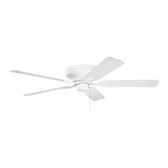
- Page 1 52" BASICS PRO LEGACY Product images may vary slightly from actual product. INSTRUCTION MANUAL...
- Page 2 KICHLER.COM...
-
Page 3: Table Of Contents
TABLE OF CONTENTS SAFETY RULES ............4 INSTALLING THE MOTOR HOUSING ....10 TOOLS AND MATERIALS REQUIRED ....... 5 ATTACHING THE FAN BLADES .......11 PACKAGE CONTENTS ..........5 INSTALLING THE SWITCH HOUSING .....11 MOUNTING OPTIONS ..........6 OPERATING INSTRUCTIONS .........12 HANGING THE FAN .............7 TROUBLESHOOTING ..........13 ELECTRICAL CONNECTIONS ........8 SPECIFICATIONS.............14... -
Page 4: Safety Rules
SAFETY RULES To reduce the risk of electric shock, ensure electricity has been turned off at To avoid personal injury or damage to the fan and other items, be cautious when working around or cleaning the fan. the circuit breaker or fuse box before beginning. Do not use water or detergents when cleaning the fan or fan blades. -
Page 5: Tools And Materials Required
TOOLS AND MATERIALS REQUIRED Phillips screwdriver Blade screwdriver 11mm wrench Step ladder Wire cutters PACKAGE CONTENTS Unpack your fan and check the contents. You should have the following items: A. Fan blades (5) G. Package hardware B. Ceiling mounting plate Safety cable hardware: wood screw (1), flat washer (1) C. -
Page 6: Mounting Options
MOUNTING OPTIONS If there isn't an existing UL (cUL for Canadian Installation) listed mounting box, then read the following instructions. Disconnect the power by removing fuses or turning off circuit breakers. Outlet box Secure the outlet box directly to the building structure. Use appropriate fasteners and building materials. -
Page 7: Hanging The Fan
HANGING THE FAN CUL Listed electrical REMEMBER to turn off the power. Follow the steps below to hang your fan properly. Step 1. Secure the ceiling mounting plate to the ceiling outlet box using screws and washers included with your outlet box (Fig. -
Page 8: Electrical Connections
ELECTRIC CONNECTIONS WARNING: To avoid possible electrical shock, be sure you have turned off the power at Power lines 120v the main circuit panel. Green ground Follow the steps below to connect the fan to your household wiring. Use the wire connecting nuts supplied with your fan. -
Page 9: Installation Of Safety Support
INSTALLATION OF SAFETY SUPPORT (Required for Canadian installation ONLY) A safety support cable is provided to help prevent the ceiling fan from faIling. Please install it as follows: Step 1. Attach the provided wood screw and washers to the ceiling joist next to the mounting bracket but do not tighten. -
Page 10: Installing The Motor Housing
INSTALLING THE MOTOR HOUSING Outlet box Remove the four screws located on the outside edge of the ceiling mounting plate. Lift the motor housing up and align the mounting holes in the housing to the mounting holes on the ceiling mounting plate. Screws Screws Insert each mounting screw rotating first one side to the other and then tighten... -
Page 11: Attaching The Fan Blades
ATTACHING THE FAN BLADES Step 1. Attach the blade to the blade bracket using the screws and washers as shown in Figure 10. Start screw into bracket. Repeat for the two remaining screws. Screws Step 2. Make sure the blade is straight and tighten each screw. Washers Step 3. -
Page 12: Operating Instructions
OPERATING INSTRUCTIONS Turn the power on and check the operation of your ceiling fan. The pull chain controls the fan speed as follows: Step 1. 3-speed pull chain controls the fan speed as follows: 1 pull = High, 2 pulls = Medium, 3 pulls = Low, and 4 pulls = off. NOTE: To set the fan blades in reverse, the reverse slide switch is located on the side of the switch housing. -
Page 13: Troubleshooting
TROUBLESHOOTING Problem Solution Fan will not 1. Check circuit fuses or breakers. start. 2. Check all electrical connections to ensure proper contact. CAUTION: Make sure the main power is OFF when checking any electrical connection. Fan sounds noisy. 1. Make sure all motor housing screws are snug. 2. -
Page 14: Specifications
SPECIFICATIONS Fan Size Speed Volts Amps Watts CFM/W N.W. G.W. C.F. High 0.57 57.20 152.00 3536.00 61.82 52" Medium 0.31 23.10 91.20 2121.60 91.84 1.30' 0.19 8.41 54.00 1172.29 139.39 These are approximate measurements. They do not include data for any lamps or fixtures attached to the ceiling fan. 14 | KICHLER.COM... - Page 15 KICHLER® LIGHTING 7711 EAST PLEASANT VALLEY ROAD P.O. BOX 318010 CLEVELAND, OHIO 44131-8010 CUSTOMER SERVICE 866.558.5706 8:30 AM TO 5:00 PM EST, MONDAY - FRIDAY...
- Page 16 VENTILADOR DE 52" BASICS PRO LEGACY Las imágenes del producto pueden variar levemente respecto del producto real. MANUAL DE INSTRUCCIONES...
- Page 17 KICHLER.COM...
- Page 18 ÍNDICE NORMAS DE SEGURIDAD.........4 INSTALACIÓN DE LA CAJA DEL MOTOR ....10 COLOCACIÓN DE LAS ASPAS DEL VENTILADOR..11 HERRAMIENTAS Y MATERIALES NECESARIOS..5 INSTALACIÓN DE LA CAJA DE INTERRUPTORES...11 CONTENIDO DE LA CAJA .......... 5 OPCIONES DE MONTAJE...........6 INSTRUCCIONES DE USO.......... 12 INSTALACIÓN DEL VENTILADOR .......7 RESOLUCIÓN DE PROBLEMAS .........13 CONEXIONES ELÉCTRICAS........8...
-
Page 19: Normas De Seguridad
NORMAS DE SEGURIDAD Para reducir el riesgo de sufrir una descarga eléctrica, asegúrese de Para evitar lesiones o daños al ventilador u otros objetos, sea cuidadoso al trabajar cerca del ventilador o limpiarlo. deshabilitar el circuito o cortar la electricidad de la caja de fusibles antes de comenzar. -
Page 20: Herramientas Y Materiales Necesarios
HERRAMIENTAS REQUERIDAS Destornillador Philips Destornillador plano Llave de 11 mm Escalera Cortacables CONTENIDO DE LA CAJA Abra la caja y verifique su contenido. Debe tener los siguientes ítems: Aspas del ventilador (5) G. Contenido de la bolsa de piezas Placa de montaje para Piezas metálicas del cable de seguridad: cielorraso tirafondo (1), arendala plana (1) -
Page 21: Opciones De Montaje
OPCIONES DE MONTAJE Si no tiene una caja para montaje certificada por UL (cUL para Canadá) ya instalada, entonces lea las siguientes instrucciones. Desconectar la electricidad sacando los fusibles o bajando las Caja tomacorriente llaves de circuitos. Asegure la caja tomacorriente directamente sobre la estructura del edificio. -
Page 22: Instalación Del Ventilador
INSTALACIÓN DEL VENTILADOR Caja eléctrica RECUERDE desconectar el suministro de energía eléctrica. con certificación Para instalar su ventilador de techo de manera adecuada, siga los pasos detallados a continuación. Paso 1. Fije la placa de montaje del cielorraso a la caja de distribución eléctrica utilizando los tornillos y arandelas que se incluyen con la caja de distribución (Fig. -
Page 23: Conexiones Eléctricas
CONEXIONES ELÉCTRICAS ADVERTENCIA: Para evitar posibles descargas eléctricas,asegúrese de haber Cables de alimentación 120v desconectado el suministro de energía eléctrica desde el panel de circuito principal. Conductor a tierra verde Siga los pasos a continuación para conectar el ventilador al cableado de su hogar. Utilice las tuercas para cable proporcionadas con el ventilador. -
Page 24: Instalación Del Soporte De Seguridad
INSTALACIÓN DEL SOPORTE DE SEGURIDAD (Requisito sólo para instalación en Canadá) Se incluye un cable de soporte de seguridad para evitar la caída del ventilador de techo. Por favor instale de la siguiente manera: Paso 1. Coloque el tornillo para madera y las arandelas en la viga del techo junto con el soporte de montaje, pero no lo ajuste. -
Page 25: Instalación De La Caja Del Motor
INSTALACIÓN DE LA CAJA DEL MOTOR Caja tomacorriente Retire los cuatro tornillos situados en el borde exterior de la placa de montaje del cielorraso. Levante la caja del motor y alinee los orificios de montaje de la caja con los Tornillos Tornillos orificios de montaje de la placa de montaje del cielorraso. -
Page 26: Colocación De Las Aspas Del Ventilador
COLOCACIÓN DE LAS ASPAS Paso 1. Acople el aspa al soporte para aspa utilizando los tornillos y arandelas tal como se muestra en la Figura 10. Inserte el tornillo en el soporte. Repita con los dos tornillos Tornillos restantes. Arandela Paso 2. -
Page 27: Instrucciones De Uso
INSTRUCCIONES DE FUNCIONAMIENTO Conecte la electricidad y verifique el funcionamiento de su ventilador de techo. La cadenilla control la velocidad del ventilador de la siguiente manera: Paso 1. Cadenilla de control de 3 velocidades: controla la velocidad del ventilador de la siguiente manera: Jalar 1 vez = Máximo, jalar 2 veces = Medio, jalar 3 veces = Bajo y jalar cuatro veces apaga el motor. -
Page 28: Resolución De Problemas
RESOLUCIÓN DE PROBLEMAS Problema Solución El ventilador 1. Verifique la caja de fusibles e interruptores. no enciende. 2. Verifique todas las conexiones eléctricas para asegurarse de que estén haciendo contacto correctamente. PRECAUCIÓN: Asegúrese de que la electricidad esté CORTADA antes de revisar cualquier conexión eléctrica. El ventilador Asegúrese de que todos los tornillos del armazón del motor estén bien ajustados. -
Page 29: Especificaciones
ESPECIFICACIONES Tamaño Velocidad Voltios Amperes Vatios FCM/P P.N. P.T. V.T. Alto 0.57 57.20 152.00 3536.00 61.82 52" Medio 0.31 23.10 91.20 2121.60 91.84 1.30' Bajo 0.19 8.41 54.00 1172.29 139.39 Estas son medidas aproximadas. No incluyen datos de lámparas o artefactos adjuntados al ventilador de techo. 14 | KICHLER.COM... - Page 30 KICHLER® LIGHTING 7711 EAST PLEASANT VALLEY ROAD P.O. BOX 318010 CLEVELAND, OHIO 44131-8010 ATENCIÓN AL CLIENTE 866.558.5706 8:30 AM A 5:00 PM EST, LUNES A VIERNES...
- Page 31 VENTILATEUR BASICS PRO LEGACY 52 po Le produit peut différer légèrement des illustrations. MANUEL D’INSTRUCTIONS...
- Page 32 KICHLER.COM...
- Page 33 TABLE DES MATIÈRES CONSIGNES DE SÉCURITÉ ........4 INSTALLATION DU BOÎTIER DU MOTEUR ....10 OUTILLAGE ET MATERIAUX REQUIS ......5 FIXER LES PALES DU VENTILATEUR ......11 CONTENU DE L’EMBALLAGE ........5 INSTALLATION DE LE BOÎTIER DE COMMUTATEUR ...11 OPTIONS DE MONTAGE ..........6 INSTRUCTIONS D’UTILISATION .........12 SUSPENDRE LE VENTILATEUR........7 DÉPANNAGE ..............13...
-
Page 34: Consignes De Sécurité
CONSIGNES DE SÉCURITÉ Pour réduire le risque d’électrocution, assurez-vous que l’électricité a été Éviter de placer des objets dans la trajectoire des pales. coupée au niveau du disjoncteur ou de la boîte à fusibles avant de Pour éviter des blessures ou des dommages au ventilateur et autres objets, prendre commencer. -
Page 35: Outillage Et Materiaux Requis
OUTILLAGE ET MATERIAUX REQUIS Tournevis Philips Tournevis standard Clé de 11 mm Marche-pieds Pinces coupantes CONTENU DE L’EMBALLAGE Déballez votre ventilateur et vérifiez le contenu. Vous devriez disposer des éléments suivants : A. Pales de ventilateur (5) G. Contenu du sac de pièces B. -
Page 36: Options De Montage
OPTIONS DE MONTAGE En l’absence d’une boîte de montage homologuée cUL (UL pour les États-Unis), prendre connaissance des instructions suivantes. Couper le courant en retirant les fusibles ou en déclenchant le disjoncteur. Boîte à prises Fixer la boîte à prises directement sur la structure du bâtiment. Utiliser des attaches et des matériaux de construction appropriés. -
Page 37: Suspendre Le Ventilateur
SUSPENDRE LE VENTILATEUR Boîte électrique homologuée TOUJOURS couper le courant. Suivez les étapes ci-dessous pour suspendre votre ventilateur correctement. Étape 1. Fixez la plaque de montage au plafond sur la boîte de sortie au plafond à l'aide des vis et des rondelles fournies avec la boîte de sortie (Fig. -
Page 38: Connexions Électriques
CONNEXIONS ÉLECTRIQUES Lignes AVERTISSEMENT : Pour éviter tout risque d'électrocution, s'assurer que l'alimentation d'alimentation est coupée au niveau du panneau de circuit principal. 120 V Vert Terre Procédez comme suit pour raccorder le ventilateur au câblage du domicile. Utilisez les raccords de connexion des fils fournis avec le ventilateur. -
Page 39: Installation Du Support De Sécurité
INSTALLATION DU SUPPORT DE SÉCURITÉ (Requis UNIQUEMENT dans le cas d’une installation canadienne) Le câble de support de sécurité est fourni pour empêcher que le ventilateur de plafond ne tombe; pour ce faire, il doit être installé comme suit : Étape 1. -
Page 40: Installation Du Boîtier Du Moteur
INSTALLATION DU BOÎTIER DU MOTEUR Boîte à prises Retirez les quatre vis situées sur le bord extérieur de la plaque de montage au plafond. Soulevez le boîtier du moteur et alignez les trous de montage du carter sur les trous de la plaque de montage au plafond. -
Page 41: Fixer Les Pales Du Ventilateur
FIXER LES PALES DU VENTILATEUR Étape 1. Fixez une pale au support de pale avec les vis et les rondelles fournies (voir la Fig. 10). Commencez à serrer la vis dans le support. Répétez l'opération pour les deux vis restantes. Rondelle Étape 2. -
Page 42: Instructions D'utilisation
INSTRUCTIONS D’UTILISATION Remettre sous tension et vérifier le fonctionnement du ventilateur de plafond. La chaîne de traction contrôle les trois (3) vitesses du ventilateur de plafond. Étape 1. La chaîne de tirage pur 3 vitesses contrôle la vitesse du ventilateur comme suit : Tirer 1 fois = Vitesse élevée, Tirer 2 fois = Vitesse moyenne, Tirer 3 fois = Vitesse faible et Tirer 4 fois = Arrêt. -
Page 43: Dépannage
DÉPANNAGE Problème Solution Impossible de mettre 1. Vérifiez les fusibles ou disjoncteurs de circuit. le ventilateur en 2. Vérifiez tous les raccordements électriques pour garantit un bon contact. MISES EN GARDE : Assurez-vous marche. que l’alimentation principale est COUPÉE lors de la vérification des raccordements électriques. Le ventilateur 1. -
Page 44: Spécifications
SPÉCIFICATIONS Taille Vitesse Ampérage Watt PCM/W Poids net Poids brut Pied cubes Volt Haute 0.57 57.20 152.00 3536.00 61.82 52" Moyenne 0.31 23.10 91.20 2121.60 91.84 1.30' 0.19 8.41 54.00 1172.29 139.39 Basse Ces mesures sont approximatives. Elles ne comprennent pas les données pour toutes les lampes ou les luminaires fixés au ventilateur de plafond. - Page 45 KICHLER® LIGHTING 7711 EAST PLEASANT VALLEY ROAD P.O. BOX 318010 CLEVELAND, OHIO 44131-8010 SERVICE À LA CLIENTÈLE 866.558.5706 De 08h30 à 17h (heure normale du l'Est), du lundi au vendredi...
Need help?
Do you have a question about the 330020SBK and is the answer not in the manual?
Questions and answers