
Related Manuals for Atlanta Attachment Company 1312N65


Summary of Contents for Atlanta Attachment Company 1312N65
- Page 1 Model 1312N65 Rev 1.5 Updated March 22, 2018 Technical Manual & Parts Lists Atlanta Attachment Company 362 Industrial Park Drive Lawrenceville, GA 30046 770-963-7369 • www.atlatt.com...
- Page 3 Attachment Company. In addition to any confidentiality and non-disclosure obligations that currently exist between you and Atlanta Attachment Company, your use of these materials serves as an acknowledgment of the confidential and proprietary nature of these materials and your duty not to make any unauthorized use or disclosure of these materials.
-
Page 4: Table Of Contents
Technical Manual & Parts Lists Contents Important Safety Instruction ........................1 Liability ..............................2 Safety Equipment on the Machines ......................3 Protective Eyewear ............................. 4 Important Notices............................5 Maintenance ..............................7 Repair ................................8 A Word to the End User..........................9 Safety Precautions ............................ - Page 5 4500518 LOOPER TAKE-UP ASSEMBLY ................... 59 4500534 LOOPER HOLDER ASSEMBLY .................... 60 1312144 Control Button Panel........................61 1312N65-PD PNEUMATIC DIAGRAM ....................63 1312N65-WD WIRING DIAGRAM ......................64 Signal Word! (Characterizes the severity of the danger) Note (describes the danger and informs how to proceed)
-
Page 6: Important Safety Instruction
Mandatory Information All persons operating and/or working on the 1312N65, should read and understand all parts of the Safety Instructions. This applies, in particular, for persons who only operate and/or work on the unit occasionally (e.g. for maintenance and repair). Persons who have difficulty reading must receive particularly thorough instruction. -
Page 7: Liability
Technical Manual & Parts Lists Liability The machine should only be operated when in perfect working order, with due regard for safety and the potential dangers, as well as in accordance with the Instruction Material. Faults and malfunctions capable of impairing safety should be remedied immediately. We cannot accept any liability for personal injury or property damage due to operator errors or non-compliance with the safety instructions contained in this booklet. -
Page 8: Safety Equipment On The Machines
Manual Técnico & Lista de Partes A Word to the Operator The greatest danger inherent in our machines: is that of fingers, hands or loose clothing being drawn into a machine by live, coasting or rotating tools or assemblies or of being cut by sharp tools or burned by hot elements. LWAYS BE CONSCIOUS OF THESE DANGERS Safety Equipment on the Machines All machines are delivered with safety equipment, which shall not be removed or... -
Page 9: Protective Eyewear
Technical Manual & Parts Lists Protective Eyewear Protective eyewear that has been tested by the local authorities should be worn whenever there is a possibility of loose or flying objects or particles such as when cleaning the machine with compressed air. Tools Always count the number of tools in your possession before starting work on the machine. -
Page 10: Important Notices
Manual Técnico & Lista de Partes Important Notices Reporting and Fighting Fires Read the instructions posted in the factory with regard to reporting fires and the emergency exits. Make sure you know exactly where the fire extinguishers and sprinkler systems are located and how they are operated. - Page 11 Technical Manual & Parts Lists - Kinetic energy - Note that some motors or spindles, for example, may continue to run or coast run on after being switched off. - Potential energy - Individual assemblies may need to be secured if necessary for repair work. Delivery of the Machine/Packaging Note any markings on the packaging, such as weights, lifting points and special information.
-
Page 12: Maintenance
Manual Técnico & Lista de Partes Protect against influences from the surroundings: no structure-borne vibrations, no grinding dust, or chemical vapors. Protect against unauthorized access. Ensure that the machine and accessories are set up in a stable position. Ensure easy access for operation and maintenance (Instruction Manual and layout diagram); also verify that the floor is strong enough to carry the weight of the machine. -
Page 13: Repair
Technical Manual & Parts Lists Repair Replacement Parts We cannot accept any liability whatsoever for damage due to the use of parts made by other manufacturers or due to unqualified repair or modification of the machine. Repair, Electrical The power supply must be switched off (master switch off) and secured so that it cannot be switched on again inadvertently before starting any work on live parts. -
Page 14: A Word To The End User
Manual Técnico & Lista de Partes A Word to the End User The end user has sole responsibility to enforce the use of safety procedures and guards on the machine. Any other safety devices or procedures due to local regulations should be should be retrofitted in accordance to these regulations and/or the EC Directive on the safety of machines. -
Page 15: Multi-Needle Quilter
Technical Manual & Parts Lists Multi-needle Quilter The Multi-needle Quilter is a straight line chain stitch machine. The quilter has a quarter inch needle spacing and adjustable loopers, too allow for a great variety of patterns to be utilized. The maximum material width is 18 inches through the Multi-needle quilter but the sew pattern from the quilter is 10 inches. -
Page 16: Threading Multi-Needle Quilter
Manual Técnico & Lista de Partes Threading Multi-needle Quilter Needle threads are located to the right of the Multi-needle Quilter, while the Looper threads are located under the table top. Thread is routed through the sensors and tension disks. The Multi-needle Quilter has a take up bar for both the needle and looper thread and must be utilized to provide quality stitches. -
Page 17: Multi-Needle Quilter Layout
Technical Manual & Parts Lists Multi-needle Quilter Layout The Multi-needle Quilter is a straight line chain stitch machine. The quilter has a quarter inch needle spacing and adjustable loopers, which allows for a variable line pattern across the border. The next few pages are to help familiarize the technician with the mechanical lay out of the quilter. - Page 18 Manual Técnico & Lista de Partes Left Side Needle Drive Pulley/Crank Drive Roller Eccentric Spreader Bar Eccentric Belt Tensioner Spreader Bar Crank Arm Looper Thread Take-up Drive Pulley/Eccentric Daily Lubrication needed at these points...
- Page 19 Technical Manual & Parts Lists a. Looper rocker arm The Multi-needle Quilter is equipped with a rocker arm on the looper shaft, which enables the technician to rotate the loopers down and forward to ease in looper threading. The technician must manually rotate the Multi-needle Quilter to the Needle TDC position; then must pull on the looper shaft detent, located on the front lower left of the quilter, in order to unlock the shaft.
-
Page 20: Multi-Needle Quilter Adjustments
Manual Técnico & Lista de Partes Multi-needle Quilter Adjustments Please follow all safety procedures, turning off power is recommended. a. Adjusting the needle height of the needle bar Needle System SN328-22: Set the needle bar so that when the needle bar has reached to top dead point, the needle point is approximately 6.8mm (0.267 inches) from the throat plate. - Page 21 Technical Manual & Parts Lists e. Thread spreader Thread spreader is very important to obtain stable stitches without skip-stitching in case of normal feed sewing. f. The timing of thread spreader against the needle When the pointed end of the descending needle arrives at the level of upper surface of the looper, adjust such that the inside surface of the...
- Page 22 Manual Técnico & Lista de Partes h. Looper Thread take-up Bars Looper thread take-up bars help to avoid material puckering; adjust the looper take-up so that the bottom of one bar is aligned with the lower side the other two with a little earlier timing, that way the looper thread will not be drawn too much and a favorable...
-
Page 23: Quilter Timing Setup
Technical Manual & Parts Lists Quilter Timing Setup Warning: Be sure to follow Lockout/Tagout procedures before attempting any adjustments to the quilter assembly. Follow steps 1 through 7 in order to properly setup the sew operation of the quilter. 1. Needle bar height. a.-Set machine at needle bar BDC (bottom dead center) b.-Adjust height to 0.30 (7.5mm) inside the window cutout by the fasteners at each end of the needle bar. - Page 24 Manual Técnico & Lista de Partes 2. Synchronizing looper to needle a.-Set machine at needle bar BDC b.-Adjust looper rear point of reversal by the eccentric marked “L” on the left side of quilter.
-
Page 25: Setting The Loop Stroke
Technical Manual & Parts Lists Setting the loop stroke a.-Set machine at needle bar BDC b.-With the loopers at rear point of reversal there should be approximately 0.08 (2mm) clearance between the point of looper to the rear edge of needle. To obtain this, loosen the clamping screw on the extreme left end of the looper shaft and position looper. -
Page 26: Thread Retainer Timing
Manual Técnico & Lista de Partes Thread retainer timing a.-With the descending point of the needle just below and behind the eye of the reversing looper the retainer should be at the extreme right position. Adjust by turning eccentric marked “S”. Located on the right side of quilter. -
Page 27: Thread Retainer Position
Technical Manual & Parts Lists Thread retainer position a.-Adjust the thread retainer end to have a clearance of 0.02 (0.5mm) to the needle. At the same time, the flat surface should be parallel to the bottom of the stitch plate. Adjust with the fastening screw. b-Adjust the clearance of the retainers over the top of the loopers to be approximately the thread thickness. -
Page 28: Looper Thread Take-Up Timing
Manual Técnico & Lista de Partes Looper thread take-up timing. a.-The looper thread should be at max pull off at the same time the retainer reaches extreme right. Adjust with the eccentric marked “T” located in the right side. Note: Amount of pull off should be set is determined by thread type. Arrows indicate the bar extreme right position... -
Page 29: Puller Timing
Technical Manual & Parts Lists Puller timing. a.-The puller should be timed so that the puller movement only occurs when the needles are out of the fabric. Adjust with eccentric marked “P” on the right side of the machine. -
Page 30: Assembly Drawings & Parts Lists
Company. In addition to any confidentiality and non-disclosure obligations that currently exist between you and Atlanta Attachment Company, your use of these materials serves as an acknowledgment of the confidential and proprietary nature of these materials and your duty not to make any unauthorized use or... - Page 31 Technical Manual & Parts Lists...
- Page 32 Manual Técnico & Lista de Partes...
-
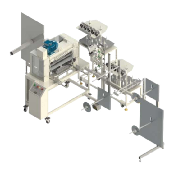
Page 33: 11312N65 Decorative Border Work Station
MULTI-NEEDLE SEW ASBLY 1312116 REGULATOR PANEL 1312121 THREAD GUIDE, NEEDLE THRD 1312128 THREAD STAND ASSY 1312141 ROLL HOLDER ASSY. *AR 1312N65-PD DIAGRAM.PNEUMATIC *AR 1312N65-WD DIAGRAM,WIRING 1961-KIT10 BORDER SPLICING ASSY 4500650 REWINDER, BORDER MM9280K33 GROMMET,FLANGE,1.03 ID SSHC10144 SCREW,HEX,5/16-18X2-1/4 WWFS5/16 WASHER,FLAT,SAE,5/16 WWL5/16... - Page 34 Manual Técnico & Lista de Partes...
-
Page 35: 1312097 Multi-Needle Sew Assembly
Technical Manual & Parts Lists 1312097 MULTI-NEEDLE SEW ASSEMBLY AAC Drawing Number 1312097 Rev 3 NO QTY PART # DESCRIPTION 1312108 WELDMENT, FRAME 1312133 CONTROL BOX 1334-1005 MOUNT, ANGLE, UPPER 1334-1006 MOUNT,LOCKING HANDLE 1335-310 STOP BLOCK,FRONT 1961-115 LEG WELDMENT 4500118 GUARD, ROLLER 4500198 TENSION ASM. -
Page 36: 1312116 Regulator Panel
Manual Técnico & Lista de Partes 1312116 REGULATOR PANEL AAC Drawing Number 1312116 Rev 0 NO QTY PART # DESCRIPTION 4500256 BRACKET,PNEUMATIC AA198-503B REG,0-30 W/GAUGE& BRKT, R AA198-5110 FILTER/REGULATOR/LOCKOUT AAFNAN200-02 MUFFLER,1/8 NPT AAQME-3-4 MALE ELBOW 3/8OD TUBE AAQME-4-4 ELBOW, MALE,1/4X1/4NPT AAQME-5-4 ELBOW, MALE 5/32X1/4NPT NNK1/4-20... -
Page 37: 4500198 Tension Assembly Looper Thread
Technical Manual & Parts Lists 4500198 TENSION ASSEMBLY LOOPER THREAD AAC Drawing Number 4500198 Rev 0 NO QTY PART # DESCRIPTION 12 268333 LOOPER THD TENSION GUIDE 12 415294 LOOPER THREAD TENSION 4500197 MOUNT, BRACKET 4500815 BRKT, THREAD TENS. SSHC98032 10-32X1/2 HEX HD WWL10 WASHER,LOCK,#10... - Page 38 Manual Técnico & Lista de Partes...
-
Page 39: 1312128 Thread Stand Assembly
Technical Manual & Parts Lists 1312128 THREAD STAND ASSEMBLY AAC Drawing Number 1312128 Rev 1 NO QTY PART # DESCRIPTION 0411-1063 THREADED ROD 1312122 THREAD STAND, NEEDLES 1312126 THREAD STAND FRAME ASSY. 4003-BTSR12 BTSR SENSOR PCB, 12 POS 4500347 PRE-TENSION ASSY 4500816 THREAD GUIDE, NEEDLE AAF1/4... - Page 40 Manual Técnico & Lista de Partes...
-
Page 41: 1312122 Thread Stand, Needles
Technical Manual & Parts Lists 1312122 THREAD STAND, NEEDLES AAC Drawing Number 1312122 Rev 3 NO QTY PART # DESCRIPTION 1312143 PLATE, THREAD BREAK 4003-IS3WT2E SENSOR,THREAD BRK,,1329 40085790 ROD, THREAD SPOOL 40085791 CONE,SPOOL RETAINER 4500130 POLE, THREAD STAND 4500133 PLATE, THREAD STAND 4500185 FOAM, THREAD STAND 97-2250A... - Page 42 Manual Técnico & Lista de Partes...
-
Page 43: 1312141 Roll Holder Assembly
Technical Manual & Parts Lists 1312141 ROLL HOLDER ASSEMBLY AAC Drawing Number 1312141 Rev 5 NO QTY PART # DESCRIPTION NO QTY PART # DESCRIPTION 1312080 TUBE,F,CRS,1X2X48.38L,D ROD CROSS BLOCK 1312086 SUPPORT, TENSIONER,DUAL FFRK44T4EX3B CABLE,EXTENSION,3 WAY 1312087 TUBE,HORIZ W/FLANGE FFT18FF100Q EYE,FIXED FIELD, 4IN 1312163 TUBE,14 GA, 1X2X24.00... - Page 44 Manual Técnico & Lista de Partes...
-
Page 45: 1961-Kit 10 Border Splicing Assembly
Technical Manual & Parts Lists 1961-KIT 10 BORDER SPLICING ASSEMBLY AAC Drawing Number 9002027 Rev 9 PART # DESCRIPTION 1278-6161 FOOT SWITCH MODIFICATION 1961-005 BASE,MNT,BAG CLOSER 1961-008 RISER,BAG CLOSER 1961-014 MTG BRKT,BAG CLOSER 1961171 PEDAL MOUNT PLATE,W/GUARD 1961175 GUARD ASSY, BC-1 AAF3/16 CLAMP, BLACK PLASTIC BC-1... -
Page 46: 4500650 Rewinder Border
Manual Técnico & Lista de Partes 4500650 REWINDER BORDER AAC Drawing Number 4500650 Rev 1 NO QTY PART # DESCRIPTION 1961-320M REWIND ASSY W/0 SLEEVE 1961-372 SLEEVE, REWIND, 18" CAP 1961-374A HANDLE, SLEEVE 4500106 TENSION ROD ASSY SSBC98032 10-32 X 1/2 BUTTON CAP SC SSHC01048 1/4-20 X 3/4 HEX CAP WWF1/4... -
Page 47: 4500230 Guard, Quilter Left Side
Technical Manual & Parts Lists 4500230 GUARD, QUILTER LEFT SIDE AAC Drawing Number 4500230 Rev 0 NO QTY PART # DESCRIPTION 4500058 GUARD, BELT 4500124 GUARD, WINDOW 4500129 GUARD, MOTOR 4500229 HINGE,PIANO,S/S,1.06 OPEN 4500231 PLATE,NUT,4-40@.531CTC 4500832 GUARD, LT SIDE MM1590A13 LATCH, DRAW PULL NNK6-32 KEP NUT, 6-32... -
Page 48: 4500233 Guard, Quilter Right Side
Manual Técnico & Lista de Partes 4500233 GUARD, QUILTER RIGHT SIDE AAC Drawing Number 4500233 Rev 0 NO QTY PART # DESCRIPTION 4500124 GUARD, WINDOW 4500229 HINGE,PIANO,S/S,1.06 4500231 PLATE,NUT,4-40@.531CTC 4500833 GUARD, RT SIDE MM1590A1 LATCH, DRAW PULL NNK6-32 KEP NUT, 6-32 SSFC80024 6-32 X 3/8 FLAT CAP SSPP70016... - Page 49 Technical Manual & Parts Lists...
- Page 50 Manual Técnico & Lista de Partes...
- Page 51 Technical Manual & Parts Lists...
- Page 52 Manual Técnico & Lista de Partes...
-
Page 53: 4500500 Multi-Needle Quilter
Technical Manual & Parts Lists 4500500 MULTI-NEEDLE QUILTER AAC Drawing Number 4500500 Rev 10 PART # DESCRIPTION PART # DESCRIPTION 1335Q-130A ROD, SS 3/8 X 24 BBRCB081214 BEARING,NEEDLE,.500B,CLUTCH 66621 THREAD RETAINER BBTRA613 W ASHER,THRUST,STL, .375B 281208 LOOPER,300U SINGER BBTT1001 W ASHER,THRUST,BRONZE 415053 STUD,NEEDLE BAR bbtt5906k517... - Page 54 Manual Técnico & Lista de Partes...
-
Page 55: 1312133 Control Box
Technical Manual & Parts Lists 1312133 CONTROL BOX AAC Drawing Number 1312133 Rev 4 NO QTY PART# DESCRIPTION 1278-6160M FOOT PEDAL ASSY, 1 PEDAL 1312N65-WD DIAGRAM,WIRING 1312130 CONTROL PANEL,FRONT 1312132 CONTROL BOX,BACK 1312135 COVER,CONTROL BOX 1312144 CONTROL BUTTON PANEL 1312145... - Page 56 Manual Técnico & Lista de Partes...
-
Page 57: 1961-320M Rewind Assembly W/O Sleeve
Technical Manual & Parts Lists 1961-320M REWIND ASSEMBLY W/O SLEEVE AAC Drawing Number 9001619 Rev 5 PART # DESCRIPTION PART # DESCRIPTION 1961-319 PLATE,NUT,3/8-16@3.00 CTC SSHC01048 1/4-20 X 3/4 HEX CAP 1961-320SWD WIRING DIAGRAM,1/2HP MTR SSHC01096 1/4-20 X 1-1/2 HHCS 1961-321 PLATE, ADAPTOR, AIR CLUTC SSHC01160... -
Page 58: 4500276 Middle Support Assembly
Manual Técnico & Lista de Partes 4500276 MIDDLE SUPPORT ASSEMBLY AAC Drawing Number 4500276 Rev 0 NO QTY PART # DESCRIPTION NO QTY PART # DESCRIPTION 4500010 BOLT, ADAPTER CCCL5F CLAMP COLLAR,5/16" BORE 4500016 GUIDE, FOOT ROD MMSH-59 RING,SNAP,EXTERNAL 4500516 GUIDE, FOOT ROD SSHC01048 1/4-20 X 3/4 HEX CAP... -
Page 59: 4500277 Left Side Plate Assembly
Technical Manual & Parts Lists 4500277 LEFT SIDE PLATE ASSEMBLY AAC Drawing Number 4500277 Rev 0 NO QTY PART # DESCRIPTION 4500520 PLATE, LEFT SIDE 4500706 RETAINER, BEARING BB1623DCTN BEARING, BALL,.625B MMSH-59 RING,SNAP,EXTERNAL SSFC90024 8-32 X 3/8 FL ALN CAP UUFL06 BEARING, LINEAR, 3/8ID... -
Page 60: 4500278 Right Side Plate Assembly
Manual Técnico & Lista de Partes 4500278 RIGHT SIDE PLATE ASSEMBLY AAC Drawing Number 4500278 Rev 0 NO QTY PART # DESCRIPTION 4500519 PLATE, RIGHT SIDE 4500706 RETAINER, BEARING BB1623DCTN BEARING, BALL,.625B MMSH-59 RING,SNAP,EXTERNAL 16 SSFC90024 8-32 X 3/8 FL ALN CAP UUFL06 BEARING, LINEAR, 3/8ID... -
Page 61: 4500279 Looper T/U Rod Assembly
Technical Manual & Parts Lists 4500279 LOOPER T/U ROD ASSEMBLY AAC Drawing Number 4500279 Rev 0 NO QTY PART # DESCRIPTION 1325-12 ROD END, BB 4500261 ROD, ADJUSTMENT BBAW-4 BEARI NG,ROD END,FEMALE NNJ1/4-28 NUT, HEX, JAM, 1/4-28 NNJ5/16-24 NUT,JAM,5/16-24... -
Page 62: 4500280 Spreader Drive Rod Assembly
Manual Técnico & Lista de Partes 4500280 SPREADER DRIVE ROD ASSEMBLY AAC Drawing Number 4500280 Rev 0 PART # DESCRIPTION 1325-12 ROD END, BB NNJ1/4-28 NUT, HEX, JAM, 1/4-28 BBAW-4 BEARI NG,ROD END,FEMALE 4500260 ROD, ADJUSTMENT NNJ5/16-24 NUT,JAM,5/16-24... -
Page 63: 4500281 Looper Drive Rod Assembly
Technical Manual & Parts Lists 4500281 LOOPER DRIVE ROD ASSEMBLY AAC Drawing Number 4500281 Rev 0 PART # DESCRIPTION 1325-12 ROD END, BB 4500265 ROD, ADJUSTMENT BBAW-4 BEARI NG,ROD END,FEMALE NNJ1/4-28 NUT, HEX, JAM, 1/4-28 NNJ5/16-24 NUT,JAM,5/16-24... -
Page 64: 4500518 Looper Take-Up Assembly
Manual Técnico & Lista de Partes 4500518 LOOPER TAKE-UP ASSEMBLY AAC Drawing Number 4500518 Rev 0 NO QTY PART # DESCRIPTION 1 4500524 GUI DE ROD 2 4500807 ARM, SWI NG 1 4500809 ROD, DRI VER 1 4500810 BLOCK, BEARI NG 1 4500811 ARM, LI NK 2 4500812... -
Page 65: 4500534 Looper Holder Assembly
Technical Manual & Parts Lists 4500534 LOOPER HOLDER ASSEMBLY AAC Drawing Number 4500534 Rev 1 NO QTY PART # DESCRIPTION 4500532 LOOPER HOLDER CLAMP 4500533 LOOPER HOLDER, 22 POS SSM350478 FILISTER,7/64-48, 17/64L SSSC98048 10-32 X 3/4 SOC CAP SSSC98064 10-32 X 1 SOC CAP... -
Page 66: 1312144 Control Button Panel
1312144 Control Button Panel AAC Drawing Number 1312144 Rev 3 NO QTY PART # DESCRIPTION 0411-1950C CABLE,LED,YELLOW,24VDC 1312134 CONTROL BUTTON PANEL *1 1312N65-LAB LABEL, CONT. PANEL AAQME-5-8 QUICK MALE ELBOW AAV41V VALVE,TOGGLE EE3X01 BLOCK,P.B. CONTACT, N.C. EE3X10 BLOCK,P.B. CONTACT, N.O. - Page 67 Technical Manual & Parts Lists...
-
Page 68: 1312N65-Pd Pneumatic Diagram
Manual Técnico & Lista de Partes 1312N65-PD PNEUMATIC DIAGRAM... -
Page 69: 1312N65-Wd Wiring Diagram
Technical Manual & Parts Lists 1312N65-WD WIRING DIAGRAM... - Page 70 Manual Técnico & Lista de Partes...
- Page 71 Atlanta Attachment Company (AAC) Statement of Warranty Manufactured Products Atlanta Attachment Company warrants manufactured products to be free from defects in material and workmanship for a period of eight hundred (800) hours of operation or one hundred (100) days whichever comes first. Atlanta Attachment Company warrants all electrical components of the Serial Bus System to be free from defects in material or workmanship for a period of thirty six (36) months.
- Page 72 Declaración de Garantía Productos Manufacturados Atlanta Attachment Company garantiza que los productos de fabricación son libres de defectos de material y de mano de obra durante un período de ochocientos (800) horas de operación o cien (100) días, cual llegue primero.
- Page 74 Atlanta Attachment Company 362 Industrial Park Drive Lawrenceville, GA 30046 Printed in the USA 770-963-7369 www.atlatt.com...
Need help?
Do you have a question about the 1312N65 and is the answer not in the manual?
Questions and answers