
Related Manuals for Supermicro X12SAE-5


Summary of Contents for Supermicro X12SAE-5
- Page 1 X12SAE-5 X12SCA-5F ENGLISH 繁體中文 简体中文 日本語 한국어 QUICK REFERENCE GUIDE Revision 1.0a...
- Page 3 Should you have questions or experience difficulty, contact Supermicro's Technical Support Department for assistance. Only certified technicians should attempt to install or configure components. Read this section in its entirety before installing or configuring components in the Supermicro chassis. WARNING: This product can expose you to chemicals including lead, known to the State of California to cause cancer and birth defects or other reproductive harm.
- Page 4 X12SAE-5/X12SCA-5F QUICK REFERENCE GUIDE 限用物質含有情況標示聲明書 限 限 用 用 物 物 質 質 含 含 有 有 情 情 況 況 標 標 示 示 聲 聲 明 明 書 書 Declaration of the Presence Condition of the Restricted Substances Marking 設備名稱:主機板...
- Page 5 X12SAE-5/X12SCA-5F QUICK REFERENCE GUIDE BIOS POST Codes AMI BIOS POST Codes About AMI BIOS POST Codes The table below lists some of AMI BIOS POST codes for this motherboard. For more information, refer to https://www. supermicro.com/manuals/other/AMI_AptioV_BIOS_POST_Codes_for_SM_Motherboards.pdf. Code Description 0x32 CPU post-memory initialization is started...
-
Page 6: Device Installation
X12SAE-5/X12SCA-5F QUICK REFERENCE GUIDE M.2 Device Installation Instructions M.2 Device Installation Instructions M.2 Device Installation Type 2280 PCI-E_M.2-M3 MH10 2280 MH11 22110 MH15 2280 MH14 PCI-E_M.2-M2 2280 PCI-E_M.2-M1 Type 22110... - Page 7 X12SAE-5/X12SCA-5F QUICK REFERENCE GUIDE Notes Notes...
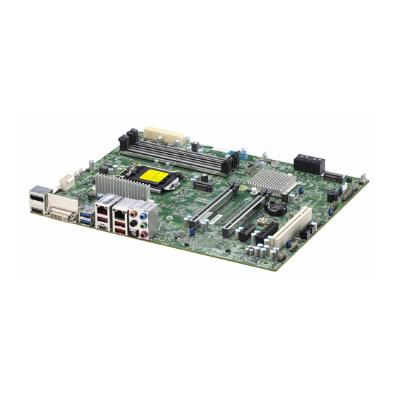
- Page 8 UPERMICR X12SAE-5 / X12SCA-5F . 1.0a uick efeRence uide Motherboard Layout and Features BACK PANEL I/O LED4 HDMI AUDIO AUDIO_FP LAN2 LAN1 IPMI_LAN USB6/7 (3.2 (10Gb)) USB8 (3.2 (20Gb)) USB4/5 (3.2 (10Gb)) JPL2 BMC_HB_LED JPG1 PCI-E_M.2-M3 JPL1 CPU_FAN1 JPAC1 MAC CODE...
-
Page 9: Jumpers And Connectors
• One Supermicro Motherboard • One Quick Reference Guide • Four SATA Cables • One I/O Shield Jumpers and Connectors Jumpers Jumper Description Default JBT1 Clear CMOS (Onboard) Short Pads to Clear CMOS Pins 1-4: External Speaker Speaker / Buzzer... -
Page 10: Led Indicators
Populating these DIMM slots with a pair of memory modules of the same type and size will result in interleaved memory, which will improve memory performance. Notes: 1) For memory optimization, use only DIMM modules that have been validated by Supermicro. For the latest memory updates, please refer to our website at http://www.supermicro.com/products/motherboard. -
Page 11: Cpu Installation
otes • Graphics shown in this quick reference guide are for illustration only. Your components may or may not look exactly the same as drawings shown in this guide. • Refer to Chapter 2 of the User Manual for detailed information on jumpers, connectors, LED indicators, memory support and CPU/motherboard installation instructions. - Page 12 UPERMICR 美超微電腦股份有限公司 X12SAE-5 / X12SCA-5F 快速參考指南版本 1.0a 主機板元件配置圖 BACK PANEL I/O LED4 HDMI AUDIO AUDIO_FP LAN2 LAN1 IPMI_LAN USB6/7 (3.2 (10Gb)) USB8 (3.2 (20Gb)) USB4/5 (3.2 (10Gb)) JPL2 BMC_HB_LED JPG1 PCI-E_M.2-M3 JPL1 CPU_FAN1 JPAC1 MAC CODE CATERR_LED IPMI CODE MH10...
- Page 13 單一主機板包裝盒內容清單 • Supermicro 主機板 x1 • 快速參考指南 • SATA 訊號線 x4 • 後檔板 x1 跳線器/連接埠 跳線器 (Jumper) 跳線器 說明 預設值 JBT1 組態資料清除 (內建) 設為短路清除 CMOS 資料 針腳 1-4:外接喇叭 喇叭 / 蜂鳴器 針腳 3-4:蜂鳴器 JPAC1 針腳 1-2 (啟用) 啟用/停用音源 JPG1 啟用/停用 VGA (僅適用於 X12SCA-5F) 針腳...
- Page 14 主機故障識別燈 (需配合相關軟體) 橘燈恆亮:該機故障 LED4 單位識別指示燈 (僅適用於 X12SCA-5F IPMI) 藍燈恆亮:識別中 PWR_LED 內建電源指示燈 綠燈恆亮:開啟 中央處理器和記憶體支援 主機板 X12SAE-5/X12SCA-5F 支援單顆 Intel Xeon W-1200/W-1300 、第十代及十一代 Intel Core i9/i7/i5/i3 系列處理器。記憶體支援 Unbuffered (UDIMM) ECC/Non-ECC DDR4 128 GB , 288 支針腳記憶體插槽,其傳輸頻率最高可達 3200MHz ,容量最高可達 及四根 (2DPC) 。欲取得雙通道效能,請安裝成對相同型號與速度之記憶體。 註: 請安裝使用本公司所認可的記憶體模組以達記憶體模組最佳化。更多的記憶體模組相關訊息,請參閱本公司...
- Page 15 備註 • 快速參考指南中的圖例僅供安裝及操作說明使用,可能與實際產品外觀不同。 • 欲知更多跳線器/連接埠/指示燈/記憶體/主機板/中央處理器的安裝相關資訊,請參閱 X12SAe-5 / X12SCA-5F 使用手冊》第二章。 《 upermicro 中央處理器安裝方式 散熱器安裝方式 針腳 1 Push down Lock Unlock 前控制面板配置 (JF1) Ground 接地 非可遮蔽中斷 Power LED 電源LED Vcc電壓 Vcc電壓 HDD LED 硬碟機LED NIC1 LED Vcc電壓 網卡1之LED Vcc電壓 NIC2 LED 網卡2之LED OH/Fan Fail LED 過熱及風扇故障LED...
- Page 16 UPERMICR 美超微电脑股份有限公司 X12SAE-5 / X12SCA-5F 快速参考指南版本 1.0a 主板组件配置图 BACK PANEL I/O LED4 HDMI AUDIO AUDIO_FP LAN2 LAN1 IPMI_LAN USB6/7 (3.2 (10Gb)) USB8 (3.2 (20Gb)) USB4/5 (3.2 (10Gb)) JPL2 BMC_HB_LED JPG1 PCI-E_M.2-M3 JPL1 CPU_FAN1 JPAC1 MAC CODE CATERR_LED IPMI CODE MH10...
- Page 17 单个主板包装盒内容清单 • Supermicro 主板 x1 • 快速参考指南 数据线 x4 • SATA • 后档板 x1 跳线器/端口 跳线器 (Jumper) 跳线器 说明 默认值 JBT1 组态资料清除 (内置) 设为短路清除 CMOS 资料 针脚 1-4:外接喇叭 喇叭 / 蜂鸣器 针脚 3-4:蜂鸣器 JPAC1 针脚 1-2 (启用) 启用/停用音源 JPG1 启用/停用 VGA (仅适用于 X12SCA-5F) 针脚...
- Page 18 CATERR_LED 主机故障识别灯 (需配合相关软件) 橙色灯常亮:该机故障 LED4 单位识别指示灯 (仅适用于 X12SCA-5F IPMI) 蓝灯常亮:识别中 PWR_LED 内置电源指示灯 绿灯常亮:开启 中央处理器和内存支持 主板 X12SAE-5/X12SCA-5F 支持单个 Intel Xeon W-1200/W-1300 、第十代及十一代 Intel Core i9/i7/i5/i3 系列处理器。内存支持 Unbuffered (UDIMM) ECC/Non-ECC DDR4 ,容量最高可达 128 GB ,及四根 288 支针脚内存插槽,其传输频率最高可达 3200MHz (2DPC) 。如需获得双通道性能,请安装成对相同型号和速度的内存。 注: 请安装使用本公司认可的内存模块,以实现内存模块优化。更多的内存模块相关信息,请参阅本公司网页...
- Page 19 备注 • 快速参考指南中的图例仅供安装和操作说明使用,可能与实际产品外观有差异。 • 如需了解更多跳线器/端口/指示灯/内存/主板/中央处理器的安装相关信息,请参阅 X12SAe-5 / X12SCA-5F 《 使用手册》第二章。 upermicro 中央处理器安装方式 散热器安装方式 针脚 1 Push down Lock Unlock 前侧控制面板配置 (JF1) 接地 Ground 不可屏蔽的中断 Power LED 电源LED 硬盘 LED HDD LED NIC1 LED NIC1 LED NIC2 LED NIC2 LED OH/Fan Fail LED 过热/风扇故障LED...
- Page 20 UPERMICR X12SAE-5 / X12SCA-5F クイック参照ガイド 1.0a版 マザーボードのレイアウトと機能 バックパネルI/O LED4 HDMI AUDIO AUDIO_FP LAN2 LAN1 IPMI_LAN USB6/7 (3.2 (10Gb)) USB8 (3.2 (20Gb)) USB4/5 (3.2 (10Gb)) JPL2 BMC_HB_LED JPG1 PCI-E_M.2-M3 JPL1 CPU_FAN1 JPAC1 MAC CODE CATERR_LED IPMI CODE MH10 COM1 BAR CODE...
- Page 21 パッケージ内容 • Supermicro マザーボード 1枚 • クイック参照ガイド 1冊 • SATA ケーブル 4本 • I/O シールド 1個 ジャンパーおよびコネクタ ジャンパー ジャンパー 説明 デフォルト JBT1 CMOSクリア (基板上) CMOSクリア用の短いパッド ピン 1~4︓外部スピーカー スピーカー/ブザー ピン 3-4︓ブザー JPAC1 HD オーディオ有効化/無効化 ピン 1-2 (有効) JPG1 VGA 有効化/無効化(X12SCA-5F のみ)...
- Page 22 LED4 ユニット ID(UID)LED(X12SCA-5F、IPMI のみ) ブルー オン︓ユニットの識別 PWR_LED オンボード電源 LED 緑色に点灯︓電源オン CPU およびメモリサポート The X12SAE-5/X12SCA-5F マザーボートは、単一の Intel® Xeon® W-1200/W-1300 シリーズ、第10/11世代Intel Core i9/i7/i5/i3 シリーズプロセ ッサ、最大128 GB のバッファーなし(UDIMM)ECC/非ECC メモリを、4つの288ピンメモリスロットにある最大3200MHz(2DPC)の速度でサポ ートします。これらの DIMM スロットにタイプとサイズが同じメモリモジュールのペアを装着した場合、インターリーブメモリが生成されてメモリパフォ ーマンスが向上します。 注 記 ︓1) メモリの最適化には、Supermicro によって検証済みの DIMM モジュールのみを使用してください。最新のメモリア ップデートについ ては、当社のウェブサイト(http://www.supermicro.com/products/motherboard)を参照してく ださい。...
- Page 23 注記 • 本クイック参照ガイドにある図は参考用です。お手元のコンポーネントは、本ガイドに示されている図 と異なるか、まったく同一ではない可能性があります。 • 以下に関する詳細は第2章にあるユーザーマニュアルを参照してください︓ジャンパー、コネクタ、LED インジケータ、メモリサポートおよびCPU/マザーボードインストールガイド。 CPUの設置 ヒートシンクの設置方向 ピン 1 押す ロック ロックの 解除 フロント コントロールパネル (JF1) グラウンド Ground 電源LED Power LED HDD LED HDD LED NIC1 LED NIC1 LED NIC2 LED NIC2 LED OH/ファン故障LED OH/Fan Fail LED 電源故障LED Power Fail LED #3~4 リセットボタン...
- Page 24 UPERMICR X12SAE-5 / X12SCA-5F 간편 설명서(개정판 1.0a) 메인보드 레이아웃 및 특징 후면 패널I/O LED4 HDMI AUDIO AUDIO_FP LAN2 LAN1 IPMI_LAN USB6/7 (3.2 (10Gb)) USB8 (3.2 (20Gb)) USB4/5 (3.2 (10Gb)) JPL2 BMC_HB_LED JPG1 PCI-E_M.2-M3 JPL1 CPU_FAN1 JPAC1 MAC CODE CATERR_LED IPMI CODE...
- Page 25 제품 구성물 • Supermicro 메인보드 1개 • 간편 설명서 1부 • SATA 케이블 4개 • I/O 쉴드 1개 점퍼 및 커넥터 점퍼 점퍼 설명 기본값 JBT1 CMOS초기화(온보드) CMOS 초기화용 쇼트패드 핀 1~4: 외부 스피커 핀 3-4: 버저 스피커/버저 JPAC1 HD 오디오 사용/사용 안 함...
- Page 26 의 288핀 메모리 슬롯에서 최대 128GB의 UDIMM 메모리, 최대 3200MHz(2DPC) 속도를 지원합니다. DIMM 슬롯에 동일한 유형 및 크기의 메모리 모듈을 쌍으로 채우면 인터리브 메모리가 발생하여 메모리 성능이 향상됩니다. 참고: 1) 메모리 최적화를 위해 반드시 Supermicro의 인증을 받은 DIMM 모듈을 사용해야 합니다. 최신 메모리 업데이트는 웹사이트(http://www.supermicro.com/products/motherboard)를 참조하십시오.
- Page 27 참고 • 본 간편 설명서의 그림들은 예시로만 사용됩니다. 실제 부품은 안내서에 표시된 도면과 동일하지 않을 수 있습니다. • 점퍼, 커넥터, LED 표시등, 메모리 지원 및 CPU /메인보드 설치 지침에 대한 자세 한 내용은 사용 설명서의 2장을 참조하십시오. CPU 설치 방열판 설치 핀...
- Page 28 X12SAE-5/X12SCA-5F QUICK REFERENCE GUIDE Notes Notes...
- Page 29 X12SAE-5/X12SCA-5F QUICK REFERENCE GUIDE Notes Notes...
- Page 30 X12SAE-5/X12SCA-5F QUICK REFERENCE GUIDE Notes Notes...
Need help?
Do you have a question about the X12SAE-5 and is the answer not in the manual?
Questions and answers