Table of Contents
Advertisement
Advertisement
Table of Contents

Related Manuals for Supermicro X12STL-F


Summary of Contents for Supermicro X12STL-F
- Page 1 X12STL-F USER'S MANUAL Revision 1.0...
- Page 2 State of California, USA. The State of California, County of Santa Clara shall be the exclusive venue for the resolution of any such disputes. Supermicro's total liability for all claims will not exceed the price paid for the hardware product.
- Page 3 Generation Pentium (Socket H5 - LGA 1200) series processor with up to eight cores. Built with the Intel PCH C252 chipset, the X12STL-F supports 128GB DDR4 ECC UDIMM memory with speeds of up to 3200MHz, dual 1GbE LAN (2x Intel i210) Base-T ports, and a Trusted Platform Module (TPM) header onboard.
- Page 4 Super X12STL-F User's Manual Contacting Supermicro Headquarters Address: Super Micro Computer, Inc. 980 Rock Ave. San Jose, CA 95131 U.S.A. Tel: +1 (408) 503-8000 Fax: +1 (408) 503-8008 Email: marketing@supermicro.com (General Information) support@supermicro.com (Technical Support) Website: www.supermicro.com Europe Address: Super Micro Computer B.V.
-
Page 5: Table Of Contents
Preface Table of Contents Chapter 1 Introduction 1.1 Checklist ..........................8 Quick Reference .......................11 Quick Reference Table ......................12 Motherboard Features .......................14 1.2 Processor and Chipset Overview ..................17 1.3 Special Features ........................17 Recovery from AC Power Loss ..................17 1.4 System Health Monitoring ....................17 Onboard Voltage Monitors ....................17 Fan Status Monitor with Firmware Control ...............18 Environmental Temperature Control .................18... - Page 6 Super X12STL-F User's Manual 2.6 Front Control Panel ......................35 2.7 Connectors .........................40 Power Connections ......................40 Headers ..........................42 2.7 Jumper Settings .........................48 How Jumpers Work ......................48 2.8 LED Indicators ........................52 Chapter 3 Troubleshooting 3.1 Troubleshooting Procedures ....................55 Before Power On ......................55 No Power ..........................55...
- Page 7 Appendix A BIOS Codes BIOS POST Codes ......................109 Appendix B Software B.1 Microsoft Windows OS Installation ...................110 B.2 Driver Installation ......................112 B.3 SuperDoctor 5 .........................113 ® Appendix C Standardized Warning Statements Appendix D UEFI BIOS Recovery D.1 Overview ...........................117 D.2 Recovering the UEFI BIOS Image ...................117 D.3 Recovering the BIOS Block with a USB Device ..............118...
-
Page 8: Chapter 1 Introduction
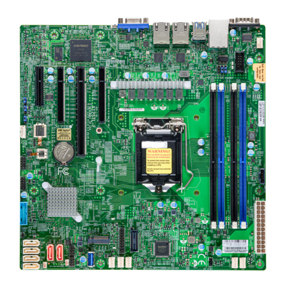
A secure data deletion tool designed to fully erase all data from storage devices can be found at our website: https://www.supermicro.com/about/policies/disclaimer.cfm?url=/wdl/ utility/Lot9_Secure_Data_Deletion_Utility/ • If you have any questions, contact our support team at: support@supermicro.com This manual may be periodically updated without notice. Check the Supermicro website for possible updates to the manual revision level. - Page 9 Chapter 1: Introduction Figure 1-1. X12STL-F Motherboard Images Front View Angle View Side View Note: All graphics shown in this manual were based upon the latest PCB revision available at the time of publication of the manual. The motherboard you received may...
- Page 10 Super X12STL-F User's Manual Figure 1-2. Motherboard Layout (not drawn to scale) JUIDB1 COM1 FAN4 USB4/5 LAN2 LAN1 USB0/1 LEDM1 BMC_LAN JPCIE7 JPCIE5 JPCIE5 JPCIE6 JPCIE4 COM2 JPWR2 JPG1 JWD1 JPME2 JIPMB1 MH11 MEGERAC LICENCE JTPM1 MH10 JPI2C1 USB2/3 JPWR1 LED3 USB6/7 (3.0)
-
Page 11: Quick Reference
Chapter 1: Introduction Quick Reference USB0/1 COM1 JUIDB1 BMC_LAN LAN1 LED1 LAN2 USB4/5 JUIDB1 COM1 FAN4 FAN4 USB4/5 LAN2 LAN1 USB0/1 LEDM1 BMC_LAN COM2 JPCIE7 JPCIE5 JPCIE5 JPCIE6 JPCIE4 COM2 JPWR2 JPWR2 JPG1 JPG1 JWD1 JWD1 JPME2 DIMMB2 JPME2 DIMMB1 JIPMB1 DIMMA2 JIPMB1... -
Page 12: Quick Reference Table
Super X12STL-F User's Manual Quick Reference Table Jumper Description Default Setting JBT1 CMOS Clear Open (Normal) JPG1 VGA Enable/Disable Pins 1-2 (Enabled) JPME2 Manufacturing Mode Pins 1-2 (Normal) Pins 1-2 PCH (Normal) JVRM1/JVRM2 VRM SMB Clock (to BMC or PCH) - Page 13 Chapter 1: Introduction Description Status LED1 Unit Identifier LED Solid Blue: Unit Identified LED3 M.2 Activity LED Blinking Green: Device Working LED4 Power Status LED Solid Green: Power On LEDM1 BMC Heartbeat LED Blinking Green: BMC Normal Green (right): Indicates Activity LAN1 &...
-
Page 14: Motherboard Features
Super X12STL-F User's Manual Motherboard Features Motherboard Features • Supports an Intel Xeon E-2300 Family and 10th Generation Pentium (Socket H5 - LGA 1200) series processor Memory • Up to 128GB of ECC UDIMM DDR4 memory with speeds of up to 3200MHz in four memory slots Note: Speed support is up to 2666MHz when a Pentium processor is installed. - Page 15 Chapter 1: Introduction Motherboard Features System Health Monitoring • Onboard voltage monitoring for +12V, +5V, +3.3V, CPU, Memory, VBAT, +3.3V stdby, CPU temperature, PCH temperature, system temperature • 6 CPU switch phase voltage regulator • CPU thermal trip support • Platform Environment Control Interface (PECI)/TSI Fan Control •...
- Page 16 Super X12STL-F User's Manual Figure 1-3. System Block Diagram IMVP 8 6 PHASE for Vcore #B-1 #B-0 PCI-E x8 PCIe Gen4 x8 #A-1 #0-7 SLOT6 ( in x16 ) #A-0 Intel CH-A PCI-E x8 PCIe Gen4 x8 DDR4 LGA1200 #8-15...
-
Page 17: Processor And Chipset Overview
Built upon the functionality and capability of the Intel Xeon E-2300 Family and 10 Generation Pentium (Socket H5 - LGA 1200) series processor and the Intel C252 chipset, the X12STL-F motherboard provides system performance, power efficiency, and feature sets to address the needs of next-generation computer users. -
Page 18: Fan Status Monitor With Firmware Control
Windows operating systems. For detailed information regarding OS support, please refer to the Supermicro website. 1.6 Power Supply As with all computer products, a stable power source is necessary for proper and reliable operation. -
Page 19: Chapter 2 Installation
Chapter 2: Installation Chapter 2 Installation 2.1 Static-Sensitive Devices Electrostatic Discharge (ESD) can damage electronic com ponents. To avoid damaging your system board, it is important to handle it very carefully. The following measures are generally sufficient to protect your equipment from ESD. Precautions •... -
Page 20: Processor And Heatsink Installation
Thermal grease is pre-applied on a new heatsink. No additional thermal grease is needed. • Refer to the Supermicro website for updates on processor support. • All graphics in this manual are for illustrations only. Your components may look different. - Page 21 Chapter 2: Installation 2. Gently lift the load lever to open the load plate. Remove the plastic protective cover. Do not touch the CPU socket contacts. 3. Locate the triangle on the CPU and CPU socket, which indicates the location of Pin 1. Holding the CPU by the edges with your thumb and index finger, align the triangle on the CPU with the triangle on the socket.
-
Page 22: Installing An Active Cpu Heatsink With Fan
Super X12STL-F User's Manual 5. Close the load plate, then gently push down the load lever into its locking position. CPU properly installed Load lever locked into place Note: You can only install the CPU in one direction. Make sure it is properly inserted into the socket before closing the load plate. - Page 23 Chapter 2: Installation 6. Align the four heatsink fasteners with the mounting holes on the motherboard. Gently push down the fasteners in a diagonal order (Example: #1 and #2, then #3 and #4) into the mounting holes until you hear a click. Then lock the fasteners by turning each one 90°...
-
Page 24: Removing The Heatsink
Super X12STL-F User's Manual Removing the Heatsink Note: We do not recommend that the CPU or heatsink be removed. However, if you do need to remove the heatsink, please follow the instructions below to remove the heatsink and prevent damage done to the CPU or other components. -
Page 25: Motherboard Installation
Chapter 2: Installation 2.3 Motherboard Installation All motherboards have standard mounting holes to fit different types of chassis. Make sure that the locations of all the mounting holes for both the motherboard and the chassis match. Although a chassis may have both plastic and metal mounting fasteners, metal ones are highly recommended because they ground the motherboard to the chassis. -
Page 26: Installing The Motherboard
Super X12STL-F User's Manual Installing the Motherboard 1. Locate the mounting holes on the motherboard and the mounting tray. Refer to the previous page for the mounting holes. 2. Install the standoffs on the mounting tray. Align the mounting holes on the motherboard against the mounting holes on the tray. -
Page 27: Memory Support And Installation
Memory Support The X12STL-F supports up to 128GB of ECC UDIMM memory with speeds of up to 3200MHz in four memory slots. Speed support is up to 2666MHz when a Pentium processor is installed. Speed support is up to 2933 MT/s for 2R2R configurations. Refer to the table below for the recommended DIMM population order. -
Page 28: General Guidelines For Optimizing Memory Performance
Super X12STL-F User's Manual General Guidelines for Optimizing Memory Performance • The blue slots must be populated first. • Always use DDR4 memory of the same type, size, and speed. • The motherboard will support odd-numbered modules (one or three modules installed). -
Page 29: Dimm Installation
Chapter 2: Installation DIMM Installation 1. Insert DIMM modules in the following JUIDB1 order: DIMMB2, DIMMA2, then DIMMB1, COM1 FAN4 USB4/5 LAN2 LAN1 DIMMA1. For the system to work properly, USB0/1 LEDM1 BMC_LAN JPCIE5 JPCIE5 JPCIE6 JPCIE7 JPCIE4 please use memory modules of the same COM2 JPWR2 type and speed. -
Page 30: Rear I/O Ports
Super X12STL-F User's Manual 2.5 Rear I/O Ports See Figure 2-1 below for the locations and descriptions of the various I/O ports on the rear of the motherboard. JUIDB1 COM1 FAN4 USB4/5 LAN2 LAN1 USB0/1 LEDM1 BMC_LAN JPCIE5 JPCIE7 JPCIE4... - Page 31 Chapter 2: Installation VGA Port A video (VGA) port is located next to LAN2 on the I/O back panel. Refer to the board layout below for the location. COM Ports There are two COM connections on this motherboard. COM1 is located on the I/O back panel. COM2 is located next to MH1.
- Page 32 Super X12STL-F User's Manual LAN Ports Two Gigabit Ethernet ports (LAN1, LAN2) are located on the I/O back panel. In addition to the LAN ports, a dedicated BMC LAN is located next to the USB0/1 ports on the back panel.
- Page 33 Chapter 2: Installation Universal Serial Bus (USB) Ports The motherboard has four USB 2.0 ports: two on the back panel (USB0/1) and two via headers (USB2/3), along with five USB 3.2 Gen1 connectors: two on the back panel (USB4/5), one Type-A (USB8) and two front accessible ports via headers (USB6/7).
- Page 34 Super X12STL-F User's Manual Unit Identifier Switch/UID LED Indicator A Unit Identifier (UID) switch and an LED indicator are located on the motherboard. The UID switch is located at UID SW. The UID switch is located at JUIDB1, which is next to the VGA port on the back panel.
-
Page 35: Front Control Panel
These connectors are designed specifically for use with Supermicro chassis. See the figure below for the descriptions of the front control panel buttons and LED indicators. - Page 36 Super X12STL-F User's Manual Power Button The Power Button connection is located on pins 1 and 2 of JF1. Momentarily contacting both pins will power on/off the system. Refer to the table below for pin definitions. Power Button Pin Definitions (JF1)
- Page 37 Chapter 2: Installation Power Fail LED The Power Fail LED connection is located on pins 5 and 6 of JF1. Refer to the table below for pin definitions. Power Fail LED Pin Definitions (JF1) Pin# Definition 3.3V PWR Supply Fail Information LED (OH/Fan Fail/PWR Fail/UID LED) The Information LED (OH/Fan Fail/PWR Fail/UID LED) connection is located on pins 7 and 8 of JF1.
- Page 38 Super X12STL-F User's Manual NIC1/NIC2 (LAN1/LAN2) The Network Interface Controller (NIC) LED connection for LAN port 1 is located on pins 11 and 12 of JF1, and LAN port 2 is on pins 9 and 10. Attach the NIC LED cables here to display network activity.
- Page 39 Chapter 2: Installation Power LED The Power LED connection is located on pins 15 and 16 of JF1. Refer to the table below for pin definitions. Power LED Pin Definitions (JF1) Pins Definition 3.3V PWR LED NMI Button The non-maskable interrupt (NMI) button header is located on pins 19 and 20 of JF1. Refer to the table below for pin definitions.
-
Page 40: Connectors
Super X12STL-F User's Manual 2.7 Connectors Power Connections ATX Power Supply Connector The 24-pin power supply connector (JPWR1) meets the ATX SSI EPS 12V specification. You must also connect the 8-pin (JPWR2) processor power connector to the power supply. ATX Power 24-pin Connector... - Page 41 Chapter 2: Installation Disk-On-Module Power Connector There are two power connector for SATA DOM (Disk-On-Module) devices located at JSD1 and JSD2. Connect appropriate cables here to provide power support for your Serial Link DOM devices. DOM Power Pin Definitions Pin# Definition Ground Ground...
-
Page 42: Headers
Super X12STL-F User's Manual Headers Fan Headers There are six 4-pin fan headers (FAN1 ~ FAN4, FANA/B) on the motherboard. All these 4-pin fan headers are backwards compatible with the traditional 3-pin fans. However, fan speed control is available for 4-pin fans only by the Thermal Management via the IPMI 2.0 interface. - Page 43 It allows the motherboard to deny access if the TPM associated with the hard drive is not installed in the system. Go to the following link for more information on the TPM: http://www.supermicro.com/manuals/other/TPM.pdf. Trusted Platform Module Header Pin Definitions...
- Page 44 Super X12STL-F User's Manual Standby Power The Standby Power header is located at JSTBY1 on the motherboard. You must have a card with a Standby Power connector and a cable to use this feature. Refer to the table below for pin definitions.
- Page 45 Chapter 2: Installation Chassis Intrusion A Chassis Intrusion header is located at JL1 on the motherboard. Attach the appropriate cable from the chassis to inform you of a chassis intrusion when the chassis is opened. Refer to the table below for pin definitions. Chassis Intrusion Pin Definitions Pin#...
- Page 46 SATA ports provide serial-link signal connections, which are faster than legacy Parallel ATA. Refer to the table below for pin definitions. Note: For more information on the SATA HostRAID configuration, refer to the Intel SATA HostRAID user's guide posted at https://www.supermicro.com/support/manuals/. 1. M.2 Slot JUIDB1 2.
- Page 47 Chapter 2: Installation Power SMB (I C) Header The Power System Management Bus (I C) connector (JPI C1) monitors the power supply, fan, and system temperatures. Refer to the table below for pin definitions. Power SMB Header Pin Definitions Pin# Definition Clock Data...
-
Page 48: Jumper Settings
Super X12STL-F User's Manual 2.7 Jumper Settings How Jumpers Work To modify the operation of the motherboard, jumpers can be used to choose between optional settings. Jumpers create shorts between two pins to change the function of the connector. Pin 1 is identified with a square solder pad on the printed circuit board. See the diagram below for an example of jumping pins 1 and 2. - Page 49 Chapter 2: Installation CMOS Clear JBT1 is used to clear CMOS. Instead of pins, this jumper consists of contact pads to prevent accidentally clearing the contents of CMOS. To Clear CMOS 1. First power down the system and unplug the power cord(s). 2.
- Page 50 Super X12STL-F User's Manual Watchdog Watchdog (JWD1) is a system monitor that can reboot the system when a software application hangs. Close pins 1-2 to reset the system if an application hangs. Close pins 2-3 to generate a non-maskable interrupt (NMI) signal for the application that hangs. Refer to the table below for jumper settings.
- Page 51 Chapter 2: Installation ME Manufacturing Mode Close pins 2-3 of jumper JPME2 to bypass SPI flash security and force the system to operate in the manufacturing mode, which will allow the user to flash the system firmware from a host server for system setting modifications.
-
Page 52: Led Indicators
Super X12STL-F User's Manual 2.8 LED Indicators Onboard Power LED LED4 is the onboard Power LED. When this LED is on, the system is on. Turn off the system and unplug the power cord before removing or installing components. Refer to the table below for more information. - Page 53 Chapter 2: Installation Unit ID LED A rear UID LED indicator (LED1) is located next to the UID switch on the motherboard. This UID indicator provides easy identification of a system unit that may need service. UID LED LED Indicator LED Color Definition Blue: On...
- Page 54 Super X12STL-F User's Manual LAN LEDs Two LAN ports (LAN 1 and LAN 2) are located on the rear I/O panel of the motherboard. Each Ethernet LAN port has two LEDs. The green LED indicates activity, while the other Link LED may be green, amber, or off to indicate the speed of the connection.
-
Page 55: Chapter 3 Troubleshooting
Chapter 3: Troubleshooting Chapter 3 Troubleshooting 3.1 Troubleshooting Procedures Use the following procedures to troubleshoot your system. If you have followed all of the procedures below and still need assistance, refer to the ‘Technical Support Procedures’ and/ or ‘Returning Merchandise for Service’ section(s) in this chapter. Always disconnect the AC power cord before adding, changing or installing any non hot-swap hardware components. -
Page 56: No Video
Super X12STL-F User's Manual No Video 1. If the power is on, but you have no video, remove all add-on cards and cables. 2. Use the speaker to determine if any beep codes are present. Refer to Appendix A for details on beep codes. -
Page 57: Losing The System's Setup Configuration
Chapter 3: Troubleshooting Losing the System's Setup Configuration 1. Make sure that you are using a high-quality power supply. A poor-quality power supply may cause the system to lose the CMOS setup information. Refer to Chapter 2 for details on recommended power supplies. 2. - Page 58 Super X12STL-F User's Manual 3. Use the minimum configuration for troubleshooting: Remove all unnecessary components (starting with add-on cards first), and use the minimum configuration (but with the CPU and a memory module installed) to identify the trouble areas. Refer to the steps listed in Section A above for proper troubleshooting procedures.
-
Page 59: Technical Support Procedures
Before contacting Technical Support, please take the following steps. Also, please note that as a motherboard manufacturer, Supermicro also sells motherboards through its channels, so it is best to first check with your distributor or reseller for troubleshooting services. They should know of any possible problems with the specific system configuration that was sold to you. -
Page 60: Frequently Asked Questions
Note: The SPI BIOS chip used on this motherboard cannot be removed. Send your motherboard back to our RMA Department at Supermicro for repair. For BIOS Recovery instructions, please refer to the AMI BIOS Recovery Instructions posted at http://www. -
Page 61: Battery Removal And Installation
Chapter 3: Troubleshooting 3.4 Battery Removal and Installation Battery Removal To remove the onboard battery, follow the steps below: 1. Power off your system and unplug your power cable. 2. Locate the onboard battery as shown below. 3. Using a tool such as a pen or a small screwdriver, push the battery lock outwards to unlock it. -
Page 62: Returning Merchandise For Service
Super X12STL-F User's Manual 3.5 Returning Merchandise for Service A receipt or copy of your invoice marked with the date of purchase is required before any warranty service will be rendered. You can obtain service by calling your vendor for a Returned Merchandise Authorization (RMA) number. -
Page 63: Chapter 4 Bios
BIOS 4.1 Introduction This chapter describes the AMIBIOS™ Setup utility for the X12STL-F motherboard. The BIOS is stored on a chip and can be easily upgraded using a flash program. Note: Due to periodic changes to the BIOS, some settings may have been added or deleted and might not yet be recorded in this manual. -
Page 64: Main Setup
Super X12STL-F User's Manual 4.2 Main Setup When entering the AMI BIOS setup utility, you start the Main setup screen. You can always return to the Main setup screen by selecting the Main tab on the top of the screen. The Main BIOS setup screen is shown below. -
Page 65: Advanced
Chapter 4: BIOS 4.3 Advanced Use the arrow keys to select Advanced setup and press <Enter> to access the submenu items: Warning: Take caution when changing the Advanced settings. An incorrect value, a very high DRAM frequency or an incorrect BIOS timing setting may cause the system to malfunction. When this occurs, restore the setting to the manufacture default setting. - Page 66 Super X12STL-F User's Manual Wait For "F1" If Error This feature forces the system to wait until the F1 key is pressed if an error occurs. The options are Disabled and Enabled. INT19 Trap Response Interrupt 19 is the software interrupt that handles the boot disk function. When this feature is set to Immediate, the ROM BIOS of the host adapters will "capture"...
- Page 67 Chapter 4: BIOS CPU Configuration The following CPU information is displayed: • Type • CPU Signature • Microcode Revision • CPU Speed • L1 Data Cache • L1 Instruction Cache • L2 Cache • L3 Cache • • SMX/TXT CPU Flex Ratio Override Use this feature to enable or disable CPU Flex Ratio Prgoraming.
- Page 68 Super X12STL-F User's Manual PECI Use this feature to enable or disable Platform Environment Control Interface (PECI). The options are Disabled and Enabled. Use this feature to enable or disable the AVX 2/3 instructions. The options are Enabled and Disabled.
- Page 69 Chapter 4: BIOS Power & Performance Configuration CPU - Power Management Control Boot Performance Mode This feature allows you to select the performance state that the BIOS will set before the operating system handoff. The options are Power Saving, Max Non-Turbo Performance and Turbo Performance.
- Page 70 Super X12STL-F User's Manual Power Limit 2 Use this feature to enable or disable Platform Power Limit 2 programming. If disabled, BIOS will program the default values for Platform Power Limit 2. The options are Disabled and Enabled. Power Limit 3 Override Use this feature to enable or disable Power Limit 3 override.
- Page 71 Chapter 4: BIOS IO MWait Redirection When set, it will map IO_read instructions to IO registers PMG_IO_BASE_ADDRBASE+offset to MWAIT (offset). The options are Disabled and Enabled. Package C-State Limit Use this feature to set the Package C-State limit. The options are C0/C1, C2, C3, C6, C7, C7s, C8, C9, C10, Cpu Default, and Auto.
- Page 72 Super X12STL-F User's Manual Chipset Warning: Setting the wrong values in the following sections may cause the system to malfunc- tion. System Agent (SA) Configuration • VT-d Supported Memory Configuration • Memory RC Version • Memory Frequency • Memory Timings (tCL-tRCD-tRP-tRAS) •...
- Page 73 Chapter 4: BIOS SA GV High Gear Use this feature to select the gear for SA GV. The options are Gear1 and Gear2. Retrain on Fast Fail This feature restarts MRC in Cold mode if SW MemTest fails during Fast flow. The options are Disabled and Enabled.
- Page 74 Super X12STL-F User's Manual DMI Configuration DMI Max Link Speed Use this feature to select DMI Max Link Speed. The options are Gen1, Gen2, and Gen3. DMI Gen3 ASPM Control Use this feature to set the Active State Power Management (ASPM) state on the System Agent (SA) side of the DMI Link.
- Page 75 Chapter 4: BIOS Number of Stop Grant Cycles This feature allows you to select the number of Stop-Grant cycles. The default setting is 1. VT-d Select Enabled to activate Intel Virtualization Technology support for Direct I/O VT-d by reporting the I/O device assignments to VMM through the DMAR ACPI Tables. This feature offers fully-protected I/O resource-sharing across the Intel platforms with greater reliability, security and availability in networking and data-sharing.
- Page 76 Super X12STL-F User's Manual PCH-IO Configuration PCH-IO Configuration PCI Express Configuration Peer Memory Write Enable Use this feature to enable or disable peer memory write. The options are Disabled and Enabled. PCI Express Root Port (1 ~ 24) This submenu allows you to configure each PCIe Root port. Click on each available port and configure the settings accordingly.
- Page 77 Chapter 4: BIOS Super IO Configuration Super IO Configuration Super IO Chip: AST2600 Serial Port 1 Configuration Serial Port 1 Configuration Select Enabled to enable the selected onboard serial port. The options are Disabled and Enabled. Device Settings This feature displays the base I/O port address and the Interrupt Request address of the selected serial port.
- Page 78 Super X12STL-F User's Manual Serial Port Console Redirection COM1 Console Redirection Select Enabled to enable console redirection support for the selected serial port. The options are Disabled and Enabled. *If the feature above is enabled, the following features are available for configuration: Console Redirection Settings...
- Page 79 Chapter 4: BIOS Flow Control Use this feature to set the flow control for Console Redirection to prevent data loss caused by buffer overflow. Send a "Stop" signal to stop sending data when the receiving buffer is full. Send a "Start" signal to start sending data when the receiving buffer is empty. The options are None and Hardware RTS/CTS.
- Page 80 Super X12STL-F User's Manual Bits per second Use this feature to set the transmission speed for a serial port used in Console Redirection. Make sure that the same speed is used in the host computer and the client computer. A lower transmission speed may be required for long and busy lines.
- Page 81 Chapter 4: BIOS Legacy Console Redirection Legacy Console Redirection Settings Redirection COM Port Use this feature to select the COM port to display redirection of Legacy OS OPROM messages. The options are COM1 and SOL/COM2. Legacy OS Redirection Resolution Use this feature to select the number of rows and columns used in Console Redirection for legacy OS support.
- Page 82 Super X12STL-F User's Manual Bits Per Second EMS This feature sets the transmission speed for a serial port used in Console Redirection. Make sure that the same speed is used in the host computer and the client computer. A lower transmission speed may be required for long and busy lines. The options are 9600, 19200, 57600, and 115200 (bits per second).
- Page 83 Chapter 4: BIOS Port 0-7 Spin Up Device Set this feature to enable or disable the PCH to initialize the device. The options are Disabled and Enabled. Port 0-7 SATA Device Type Use this feature to specify if the SATA port specified should be connected to a Solid State Drive or a Hard Disk Drive.
- Page 84 Super X12STL-F User's Manual USB Configuration USB Configuration USB Module Version: 25 USB Controllers: 1 XHCI USB Devices: 1 keyboard, 1 Mouse, 1 Hub Legacy USB Support Select Enabled to support onboard legacy USB devices. Select Auto to disable legacy support if there are no legacy USB devices present.
- Page 85 Chapter 4: BIOS PCIe/PCI/PnP Configuration Option ROM Execution Onboard Video Option ROM Use this feature to select the onboard video firmware type. The options are Disabled and EFI. Above 4GB MMIO BIOS Assignment (Available if the system supports 64-bit PCI decoding) Select Enabled to decode a PCI device that supports 64-bit in the space above 4G Address.
- Page 86 Super X12STL-F User's Manual Network Configuration Network Configuration Network Stack Select Enabled to enable Preboot Execution Environment (PXE) or Unified Extensible Firmware Interface (UEFI) for network stack support. The options are Disabled and Enabled. IPv4 PXE Support Select Enabled to enable IPv4 PXE boot support. The options are Disabled and Enabled.
- Page 87 Chapter 4: BIOS • Interface Type • MAC address • Host addresses • Route Table • Gateway addresses • DNS addresses Interface ID This feature shows the interface ID for the specified network device. DAD Transmit Count This feature sends Neighbor Solicitation messages while performing a Duplicate Address Detection (DAD) to make sure there is no IP address duplication.
- Page 88 Super X12STL-F User's Manual Discard Changes and Exit Use this feature to discard all changes and exit. Save Changes and Exit When you have completed the changes for this section, select this option to save all changes made and exit.
- Page 89 Chapter 4: BIOS Tls Auth Configuration This submenu allows you to configure Transport Layer Security (TLS) settings. Server CA Configuration Enroll Cert Enroll Cert Using File Use this feature to enroll certification from a file. Cert GUID Use this feature to input the certification GUID. Commit Changes and Exit Use this feature to save all changes and exit TLS settings.
- Page 90 Super X12STL-F User's Manual Intel I210 Gigabit Network Connection - OC:25:90:5E:E2:D4 NIC Configuration Link Speed This feature allows you to specify the port speed used for the selected boot protocol. The options are Auto Negotiated, 10 Mbps Half, 10 Mbps Full, 100 Mbps Half, and 100 Mbps Full.
- Page 91 Chapter 4: BIOS Virtual MAC Address This feature displays the Virtual MAC address for this computer. Mac addresses are six two- digit hexadecimal numbers. Driver Health This submenu provides the health status for the network drivers and controllers, and all UEFI drivers detected by the system.
-
Page 92: Event Logs
Super X12STL-F User's Manual 4.4 Event Logs Use this menu to configure Event Log settings. Change SMBIOS Event Log Settings Enabling/Disabling Options SMBIOS Event Log Change this feature to enable or disable all features of the SMBIOS Event Logging during system boot. - Page 93 Chapter 4: BIOS SMBIOS Event Log Standard Settings Log System Boot Event Select Enabled to log system boot events. The options are Enabled and Disabled. MECI Enter the increment value for the multiple event counter. Enter a number between 1 to 255. The default setting is 1.
-
Page 94: Ipmi
Super X12STL-F User's Manual 4.5 IPMI Use this menu to configure Intelligent Platform Management Interface (IPMI) settings. When you select this submenu and press <Enter>, the following information will display: • BMC Firmware Revision: This displays the firmware revision of the Baseboard Manage- ment Controller (BMC) used in your system. - Page 95 Chapter 4: BIOS When SEL is Full This feature allows you to decide what the BIOS should do when the system event log is full. Select Erase Immediately to erase all events in the log when the system event log is full. The options are Do Nothing and Erase Immediately.
- Page 96 Super X12STL-F User's Manual Configure IPv6 Support IPv6 Address Status: (This feature displays the status of IPv6 addresses). IPv6 Support: IPv6 is supported in BMC. The options are Enabled and Disabled. Configuration Address Source Use this feature to select the IP address source for this computer. If Static is selected, you will need to know the IP address of this computer and enter it to the system manually in the field.
-
Page 97: Security
Chapter 4: BIOS 4.6 Security Use this menu to configure Security settings. Please set Administrator's password first in order to set User password. If the Administrator password is cleared, the User password will be cleared as well. The length of the password should be from three to 20 characters long. - Page 98 Super X12STL-F User's Manual SMCI Security Erase Configuration This section displays the following information if a storage device is detected by the system. • HDD Name • HDD Serial Number • Security Mode • Estimated Time • Admin Pwd Status Security Function Select "Set Password"...
- Page 99 Chapter 4: BIOS Set User Password This option allows you to set up HDD User Password. It is advisable to Power Cycle System after Setting Hard Disk Password. Set Master Password This option allows you to set up Master Password. ...
- Page 100 Super X12STL-F User's Manual Key Management This submenu allows you to configure the following Key Management settings. Vendor Keys Provision Factory Key Select Enabled to install the default Secure Boot keys set by the manufacturer. The options are Disabled and Enabled.
- Page 101 Chapter 4: BIOS Delete Select ok to remove the PK. Reset the system for it to enter Setup/Audit Mode. Key Exchange Keys Use this menu to configure the setting for key exchange keys. Details Select this feature to view KEK information. Export Select this feature to export the KEK from a file system.
- Page 102 Super X12STL-F User's Manual Export Select this feature to export the dbx from a file system. Update Select Yes to load the dbx from factory default or No to load from a file or external media. Append Select Yes to load the dbx from factory default or No to load from a file or external media.
- Page 103 Chapter 4: BIOS Delete Select Yes to delete the variable or No to delete a certificate from the key database.TCG Storage Security Configuration: CT250P2SSD8 TCG Storage Password Description: Use this feature to set, modify, and clear both TCG Storage device Admin and User passwords.
-
Page 104: Boot
Super X12STL-F User's Manual 4.7 Boot Use this menu to configure Boot settings: Boot Configuration Setup Prompt Timeout Number of seconds to wait for the setup activation key. 65535(0xFFFF) means indefinite waiting. The default setting is 1. Boot Mode Select Use this feature to select the type of device that the system is going to boot from. - Page 105 Chapter 4: BIOS • Boot Option #4 • Boot Option #5 • Boot Option #6 • Boot Option #7 • Boot Option #8 • Boot Option #9 Add New Boot Option This option allows you to add a new boot option to the boot priority features for system boot. Add Boot Option This feature allows you to specify the name for the new boot option.
- Page 106 Super X12STL-F User's Manual Driver Option File Path This feature allows you to specify the file path of the driver that will be added to the boot priority list. Create After the driver option name and the file path are set, press <Enter> to enter to submenu and click OK to create the new boot option drive.
-
Page 107: Save & Exit
Chapter 4: BIOS 4.8 Save & Exit Select the Exit tab from the BIOS setup utility screen to enter the Exit BIOS Setup screen. Save Options Discard Changes and Exit Select this feature to exit the BIOS without saving any changes. Save Changes and Reset When you have completed the system configuration changes, select this option to save all changes made and reset the system. - Page 108 Super X12STL-F User's Manual Default Options Restore Optimized Defaults To set this feature, select Restore Defaults from the Exit menu and press <Enter>. These are factory settings designed for maximum system performance but not for maximum stability. Save as User Defaults To set this feature, select Save as User Defaults from the Exit menu and press <Enter>.
-
Page 109: Appendix A Bios Codes
When BIOS performs the Power On Self Test, it writes checkpoint codes to I/O port 0080h. If the computer cannot complete the boot process, a diagnostic card can be attached to the computer to read I/O port 0080h (Supermicro p/n AOC-LPC80-20). For information on AMI updates, please refer to http://www.ami.com/products/. -
Page 110: Appendix B Software
1. Create a method to access the MS Windows installation ISO file. That might be a DVD, perhaps using an external USB/SATA DVD drive or a USB flash drive. 2. Retrieve the proper RST/RSTe driver. Go to the Supermicro web page for your motherboard and click on "Download the Latest Drivers and Utilities", select the proper driver, and copy it to a USB flash drive. - Page 111 Appendix B: Software 4. During Windows Setup, continue to the dialog where you select the drives on which to install Windows. If the disk you want to use is not listed, click on “Load driver” link at the bottom left corner. Figure B-2.
-
Page 112: Driver Installation
DVD and mount the ISO file as virtual media using the iKVM console for access. You may also use a utility to extract the ISO file if preferred. Another option is to go to the Supermicro website and search for the motherboard. Find the product page for your motherboard and download the latest drivers and utilities. -
Page 113: Superdoctor ® 5
B.3 SuperDoctor ® The Supermicro SuperDoctor 5 is a program that functions in a command-line or web-based interface for Windows and Linux operating systems. The program monitors such system health information as CPU temperature, system voltages, system power consumption, fan speed, and provides alerts via email or Simple Network Management Protocol (SNMP). -
Page 114: Appendix C Standardized Warning Statements
The following statements are industry standard warnings, provided to warn the user of situations which have the potential for bodily injury. Should you have questions or experience difficulty, contact Supermicro's Technical Support department for assistance. Only certified technicians should attempt to install or configure components. - Page 115 Appendix C: Standardized Warning Statements Attention Danger d'explosion si la pile n'est pas remplacée correctement. Ne la remplacer que par une pile de type semblable ou équivalent, recommandée par le fabricant. Jeter les piles usagées conformément aux instructions du fabricant. ¡Advertencia! Existe peligro de explosión si la batería se reemplaza de manera incorrecta.
- Page 116 Super X12STL-F User's Manual Product Disposal Warning! Ultimate disposal of this product should be handled according to all national laws and regulations. 製品の廃棄 この製品を廃棄処分する場合、 国の関係する全ての法律 ・ 条例に従い処理する必要があります。 警告 本产品的废弃处理应根据所有国家的法律和规章进行。 警告 本產品的廢棄處理應根據所有國家的法律和規章進行。 Warnung Die Entsorgung dieses Produkts sollte gemäß allen Bestimmungen und Gesetzen des Landes erfolgen.
-
Page 117: Appendix D Uefi Bios Recovery
Warning: Do not upgrade the BIOS unless your system has a BIOS-related issue. Flashing the wrong BIOS can cause irreparable damage to the system. In no event shall Supermicro be liable for direct, indirect, special, incidental, or consequential damages arising from a BIOS update. -
Page 118: Recovering The Bios Block With A Usb Device
Super X12STL-F User's Manual D.3 Recovering the BIOS Block with a USB Device This feature allows the user to recover the main BIOS image using a USB-attached device without additional utilities used. A USB flash device such as a USB Flash Drive, or a USB CD/DVD ROM/RW device can be used for this purpose. - Page 119 Appendix D: UEFI BIOS Recovery Note 2: Before recovering the main BIOS image, confirm that the "Super.ROM" bi- nary image file you download is the same version or a close version meant for your motherboard. 2. Insert the USB device that contains the new BIOS image ("Super.ROM") into your USB port and reset the system until the following screen appears: 3.
- Page 120 Super X12STL-F User's Manual 4. When the screen as shown above displays, use the arrow keys to select the item "Proceed with flash update" and press the <Enter> key. You will see the BIOS recovery progress as shown in the screen below: Note: Do not interrupt the BIOS flashing process until it has completed.
- Page 121 Appendix D: UEFI BIOS Recovery 8. When the UEFI Shell prompt appears, type fs# to change the device directory path. Go to the directory that contains the BIOS package you extracted earlier from Step 6. Enter flash.nsh BIOSname.### at the prompt to start the BIOS update process. Note: Do not interrupt this process until the BIOS flashing is complete.
Need help?
Do you have a question about the X12STL-F and is the answer not in the manual?
Questions and answers