Table of Contents
Advertisement
Quick Links
Advertisement
Table of Contents

Subscribe to Our Youtube Channel
Related Manuals for WIKA OBSOLETE DI15


Summary of Contents for WIKA OBSOLETE DI15
- Page 1 Operating Instructions Digital Indicator, Model DI15 V1.3 • 02/2011 WIKA Operating Instructions DI15 WIKA Alexander Wiegand SE & Co. KG Alexander-Wiegand-Straße 30 63911 Klingenberg/Germany Telefon (+49) 93 72/132-0 Telefax (+49) 93 72/132-406 E-Mail info@wika.de www.wika.de...
- Page 2 Operating Instructions Digital Indicator DI15 I N D E X 1. SAFETY REGULATIONS ..........................3 2. INTRODUCTION............................4 3. ELECTRIC CONNECTION ..........................5 3.1. Terminal assignment ..........................5 3.2. Connection data ............................5 3.3. Connecting an input signal ........................5 3.3.1.
-
Page 3: Safety Regulations
Operating Instructions Digital Indicator DI15 1. Safety regulations This device was designed and tested considering the Safety regulations for electronic measuring devices. Faultless operation and reliability in operation of the measuring device can only be assured if the General Safety Measures and the devices specific safety regulation mentioned in this users manual are considered. 1. -
Page 4: Product Label
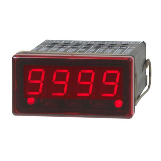
Operating Instructions Digital Indicator DI15 2. Introduction The DI15 is a microprocessor controlled displaying, monitoring and controlling device. It is equipped with one multi-function input for the connection of: - Standard transmitter signals (0 ... 20mA, 4 ... 20mA, 0 ... 50mV, 0 ... 1V, 0 ... -
Page 5: Electric Connection
Operating Instructions Digital Indicator DI15 3. Electric connection Wiring and commissioning of the device must be carried out by skilled personnel only. In case of wrong wiring the DI15 may be destroyed. We can not assume any warranty in case of wrong wiring of the device. - Page 6 Operating Instructions Digital Indicator DI15 3.3.2. Connecting a 4 ... 20mA transmitter in 2-wire-technology Supply Supply 9-28 VDC 9-28 VDC 4-20mA Transmitter 4-20mA Transmitter Supply for Transmitter with individual transmitter supply without individual transmitter supply 3.3.3. Connecting a 0(4) ... 20mA transmitter in 3-wire-technology Supply Supply 9-28 VDC...
-
Page 7: Connecting A Frequency- Or Rotation-Signal
Operating Instructions Digital Indicator DI15 3.3.6. Connecting a frequency- or rotation-signal When measuring frequency or rotation three different input signals can be selected in the device’s con- figuration. There is the possibility of connecting an active signal (= TTL, ...), a passive sensor-signal with NPN (= NPN-output, push-button, relay, ...) or PNP (= a PNP output switching to +Ub, high-side push-button, ...). -
Page 8: Connecting A Counter Signal
Operating Instructions Digital Indicator DI15 Supply Netzteil: 9-28 VDC 9-28 VDC Transducer Sig. Geber Sig. Supply for Transducer Connecting of a transducer (with individual power supply) Connecting of a transducer (without individual power supply) PNP output with external resistor wiring. PNP output and external resistor wiring. -
Page 9: Connecting Switching Outputs
Operating Instructions Digital Indicator DI15 3.4. Connecting switching outputs The device features two switching outputs, with three different operating modes for each switching out- put, which are: Low-Side: “GND-switching“ NPN output (open-collector) The switching output is connected to the negative rail of the supply voltage (connection 3 or 5) when active (switching output on). - Page 10 Operating Instructions Digital Indicator DI15 3.4.3. Connection with configured push-pull-switching output S e m i c o n d . - r e l a y Supply 9-28 VDC Connection of a semiconductor-relay 3.5. Common wiring of several DI15 Inputs and outputs are not electrically isolated. When interconnecting several DI15`s you have to make sure that there is no potential displacement.
-
Page 11: Configuration Of The Device
Operating Instructions Digital Indicator DI15 4. Configuration of the device Please note: When you are configuring the device and don’t press any button for more than 60 sec. the configuration of the device will be cancelled. The changes you made will not be saved and will be lost! Hint: The buttons 2 and 3 are featured with a ‘roll-function‘. - Page 12 Operating Instructions Digital Indicator DI15 4.2. Measuring voltage and current (0 ... 50mV, 0 ... 1V, 0 ... 2V, 0 ... 10V, 0 ...20mA, 4 ... 20mA) This chapter describes how you configure the DI15 for measuring voltage- resp. current-signals from an ex- ternal transmitter.
- Page 13 Operating Instructions Digital Indicator DI15 When pressing button 1 again, the display will show “FiLt“ (Filter = digital filter). Use button 2 and button 3 to select the desired filter [in sec.]. Selectable values: 0.01 ... 2.00 sec. Explanation: this digital filter is a digital replica of a low pass filter. Note: when using the input signal 0 ...
-
Page 14: Measuring Of Frequency (Ttl, Switching-Contact)
Operating Instructions Digital Indicator DI15 When pressing button 1 again, the display shows “outP“. (output) For configuring the outputs of the DI15, please follow the instructions shown in chapter 4.8. For setting the offset and for setting the slope-adjustment, please follow the instructions given in chapter 6. 4.4. -
Page 15: Measuring Of Rotation Speed (Ttl, Switching-Contact)
Operating Instructions Digital Indicator DI15 Display Measuring range limit Note Exceeding of the measuring-frequency is tol- Inactive erable until you reach the maximum measur- ing range limit. The measuring range is exactly bounded by active, the selected frequency-measuring-range-limit. on.Er (error indicator) When exceeding or shortfalling of the limit the device will display an error message. - Page 16 Operating Instructions Digital Indicator DI15 Use button 2 and 3 to select your desired divisor. Set the divisor to the pulses per rotation the transmitter supplies. Press button 1 to validate your selection. The display shows “diu“ again. When pressing button 1 again, the display will show “dP“ (decimal point). Use button 2 and button 3 to select the desired decimal point position.
- Page 17 Operating Instructions Digital Indicator DI15 Use button 2 or button3 (middle resp. right button) to select the desired signal edge. Display Signal edge Note The counter is triggered on the positive (ris- Positive ing) edge. The counter is triggered on the negative (fal- Negative ling) edge.
-
Page 18: Interface Mode
Operating Instructions Digital Indicator DI15 Press button 1 to validate your selection. The display shows “Li“ again. Now your device is adjusted to your signal source. The only thing left to do is to adjust the outputs of the device. When pressing button 1 again, the display will show “outP“. - Page 19 Operating Instructions Digital Indicator DI15 When pressing button 1 again, the device will display “1.dEL“ (delay of output 1). Use button 2 and button 3 to set the desired value [in sec.] for the switching-delay of output 1. Press button 1 to validate the selection. The display shows “1.dEL“ again. When pressing button 1 again, the device will display “1.out“...
- Page 20 Operating Instructions Digital Indicator DI15 Depending on the selected output function you have to make the settings for switching resp. alarm points. See description in chapter „switchpoints resp. alarm-boundaries“ for further information. Hint: The settings for the switching and alarm points can be made later in an extra menu (see chapter 5) - 20 - V1.3 02/2011...
-
Page 21: Switchpoints Resp. Alarm-Boundaries
Operating Instructions Digital Indicator DI15 5. Switchpoints resp. alarm-boundaries Please note: The settings of the switchpoints will be cancelled, when no button was pressed for more than 60 sec. changes you may have made already won‘t be saved and will be lost! Please note: The settings of the switchpoints and alarm-boundaries will automatically be reset to factory de- fault when any changes for the settings “InP”, “SEnS“... - Page 22 Operating Instructions Digital Indicator DI15 Press button 1 The device will be displaying “2.on“ (turn-on-point of output 2). (if not already done). Use button 2 and button 3 to set the desired value, the device’s output 2 should be turning on. Press button 1 to validate your selection.
- Page 23 Operating Instructions Digital Indicator DI15 5.3. Minimum/maximum-alarm (individual or common) This chapter describes how to configure the device‘s alarm boundaries for min-/max-alarm-monitoring. This instruction demands that you selected “AL.F1“ resp. “AL.F2“ as your desired output function like it is explained in chapter 4.8. Press button 1 , the device will be displaying “AL.Hi“.
-
Page 24: Offset- And Slope-Adjustment
Operating Instructions Digital Indicator DI15 6. Offset- and slope-adjustment The offset and slope-adjustment function can be used for compensating the tolerance of the used sensor, resp. for fine adjustment of the used transducer resp. transmitter. Please note: The settings of the offset- / slope-adjustment will be cancelled, if no button was pressed for more than 60 sec. -
Page 25: Min-/Max-Value Storage
Operating Instructions Digital Indicator DI15 7. Min-/max-value storage The device features a minimum/maximum-value storage. In this storage the highest resp. lowest performance data is saved. Calling of the minimum-value press button 3 shortly the device will display “Lo“ briefly, after that the min-value is displayed for about 2 sec. -
Page 26: Error Codes
Operating Instructions Digital Indicator DI15 9. Error codes When detecting an operating state which is not permissible, the device will display an error code The following error codes are defined: Error presumed cause Solution Err 1 - Input signal to high - The input sighnal must be within - Exceeding of the measuring - Sensor broken... -
Page 27: Specification
Operating Instructions Digital Indicator DI15 10. Specification Absolute maximum ratings: Performance data Limit values Connection Notes between min. max. min. max. Supply voltage 4 and 5 28 V 30 V 30V, I<1A Switching output 1 and 3, n o t s h o r t c i r c u i t p r o t e c t e d 1 and 2 2 and 3 I<200mA... - Page 28 Operating Instructions Digital Indicator DI15 Display range: (voltage-, current and frequency-measurement) -1999 ... 9999 Digit, initial value, terminal value and decimal point position arbitrary. Recommended range: < 2000 Digit Accuracy: (at nominal temperature) Standard-signals: < 0.2% FS ±1 Digit (with 0 ... 50mV: < 0.3% FS ±1Digit) RTD: <...
Need help?
Do you have a question about the OBSOLETE DI15 and is the answer not in the manual?
Questions and answers