
Related Manuals for WIKA DI30


Summary of Contents for WIKA DI30
- Page 1 Operating instructions Digital indicator model DI30 14037419 • V2.3 • 02/2012 Digital indicator model DI30 for panel mounting or wall mounting...
- Page 2 Operating instructions model DI30 page 1 - 40 © 2010 WIKA Alexander Wiegand SE & Co. KG All rights reserved. WIKA® is a registered trademark in various countries. Prior to starting any work, read the operating instructions! Keep for later use!
-
Page 3: Table Of Contents
9.1 Dismounting ..................34 9.2 Return ....................34 9.3 Disposal ..................... 35 10 Application example: DI30 and gas cylinder scale GCS-1 ....36 11 Appendix: Declaration of conformity ........... 38 Declarations of conformity can be found online at www.wika.com. WIKA operating instructions digital indicator model DI30... -
Page 4: General Information
Subject to technical modifications. Further information: - Internet address: www.wika.de / www.wika.com - Relevant data sheet: AC 80.05 - Application consultant: Tel.: (+49) 9372/132-0 Fax: (+49) 9372/132-406 E-Mail: info@wika.de WIKA operating instructions digital indicator DI30... -
Page 5: Safety
2.1 Intended use The DI30 is designed for the evaluation and display measuring transmitter signals. With the alarm outputs, it is possible to perform simple control tasks. The instrument has been designed and built solely for the intended use described here, and may only be used accordingly. - Page 6 The fuse rating of the supply voltage should not exceed a value of 1A N.B. fuse. The manufacturer shall not be liable for claims of any type based on operation contrary to the intended use. WIKA operating instructions digital indicator DI30...
-
Page 7: Personnel Qualification
Failure to comply with these instructions could result in death or serious injury and material damage. WIKA operating instructions digital indicator model DI30... -
Page 8: Labelling / Safety Marks
3: serial no. 6: connection diagram Explanation of symbols Before mounting and commissioning the instrument, ensure you read the operating instructions! CE, Communauté Européenne Instruments bearing this mark comply with the relevant European directives. WIKA operating instructions digital indicator DI30... -
Page 9: Specifications
AC 230 V, 5 A (resistive load) DC 30 V, 5 A (resistive load) Switching cycles 0,5 * 10 at max. contact rating 5 * 10 mechanically Separation as per DIN EN 50178 Characteristics as per DIN EN 60255 WIKA operating instructions digital indicator model DI30... - Page 10 Class B) and Immunity (industrial locations) Low voltage directive 2006/95/EC, EN 61010-1 { } Items in curved brackets are optional extras for additional price. For further specifications see WIKA data sheet AC 80.05 and the order documentation. WIKA operating instructions digital indicator DI30...
-
Page 11: Design And Function
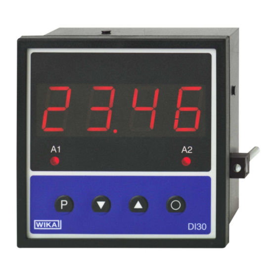
4 Design and function 4.1 Short description With the digital indicator DI30 standard signals DC 0/4…20 mA or DC 0…5/10 V can be measured. The 4 digit display shows the measurements or the scaled value of the measurement. During programming the display is used to indicate the set values and the user prompts. -
Page 12: Scope Of Delivery
Avoid exposure to the following factors: Direct sunlight or proximity to hot objects Mechanical vibration, mechanical shock (putting it down hard) Soot, vapour, dust and corrosive gases Potentially explosive environments, flammable atmospheres WIKA operating instructions digital indicator DI30... -
Page 13: Commissoning, Operation
Before assembly a cut-out must be made to accommodate the device. The sizes and tolerances are given in the technical data. On front of the DI30 are the operating and display elements. On the sides are the fixing elements to mount the device in the panel. On the back are the terminals for all the electrical connections. - Page 14 The wall-type housing consists of an upper part and a lower part. A suitable seal has been inserted in the lower part to achieve protection IP 66. In the upper part is the DI30 with its operating and display elements. On the back are the terminals for all the electrical connections.
- Page 15 3. Connecting cables have to be fed into the enclosure via the PG screws. 4. After connection the upper part of DI30 will be placed on the lower part. Using the four fixing screws, screw the upper part to the lower part. Be sure that the screws are completely tightened in order to attain ingress protection IP66.
-
Page 16: Electrical Connection
Measuring input for standard signals The input signal is connected to terminals 10 to 12. The DI30 has a voltage input and a current input, to which most conventional sensors with a standard signal output can be connected. The measuring input is galvanically isolated from the power supply (supply voltage) and the transmitter supply. - Page 17 This section gives a few examples of practical connections. a) 4…20 mA signal, 2-wire-transmitter b) 0…20 mA signal, 3-wire-transmitter The voltage drop on the transmitter supply wire is irrelevant, which is why this can also be bridged directly on the indicator. WIKA operating instructions digital indicator model DI30...
- Page 18 6 Commissoning, operation c) 0…5 V/0…10 V signal, 3-wire-transmitter The ground is bridged via the sensor, which eliminates the measuring error through the drop in voltage on the transmitter supply wires. WIKA operating instructions digital indicator DI30...
-
Page 19: Function And Operation Description
6.3 Function and operation description 6.3.1 Operation The DI30 has 4 keys ([P], [ ], [ ], [O]), with which you can parameterise and call up various functions during operation. Additionally it has a 4-digit 7-segment display and two LEDs for displaying the alarm contacts. - Page 20 An overflow of the display is indicated by horizontal bars at the top of the 7- segment display „ ¯ ¯ ¯ ¯ “. An underflow of the display is indicated by horizontal bars at the bottom of the 7 segment display „ _ _ _ _ “ WIKA operating instructions digital indicator DI30...
- Page 21 The alarm output is off below the threshold and switched on when reaching the threshold. Active below threshold The alarm output is on below the threshold and switched off on reaching the threshold. WIKA operating instructions digital indicator model DI30...
-
Page 22: Programming
P at the front. Display of e.g. program number 0 Programming Procedure The entire programming of the DI30 is done by the steps described below. Change to the programming mode Pushing the [P] key changes to programming mode. The unit goes to the lowest available program number. - Page 23 [P] key must be briefly pressed. The 6 begins flashing. Change the value from 6 to 0 using the [ ] or [ ] key. The 5 and the 7 need no change. WIKA operating instructions digital indicator model DI30...
-
Page 24: Description Of The Measuring Input
6.5 Description of the measuring input The DI30 is equipped with a measuring input for standard signals that enables standardised signals (e.g. 4 … 20 mA) from all kinds of different measuring transmitters on the market to be measured directly. - Page 25 16.5 mA before the correction. Setpoint Pressure Output Indication Desired (PN) [mbar] transmitter before indication [mA] correction (IN) (OUT) 16.5 15.0 31.0 30.0 46.0 40.0 11.4 57.0 60.0 14.7 73.5 75.0 20.0 100.0 100.0 WIKA operating instructions digital indicator model DI30...
-
Page 26: Description Of Device Parameters
6 Commissoning, operation 6.6 Description of device parameters The DI30 has a number of unit parameters with which the function of the indicator can be adjusted to the relevant measuring tasks. Because of the large number of these settings and the limited possibility of displaying them on the 7-segment display, the parameters have been given consecutive numbers. - Page 27 The parameterised user level PN52 is active as long as the locking code PN51 and the access code PN50 are different. On delivery of the DI30 both parameters are set to 0000, so that the programming lock is deactivated.
- Page 28 The behaviour of the alarm outputs can be influenced via various program numbers. The data refer to the scaled measurement and are updated with the set measuring time. A description of the various parameters is given in chapter “6.3.4 Description of alarm outputs”. WIKA operating instructions digital indicator DI30...
- Page 29 PN200: Serial number Under PN200 the 4-digit serial number can be called up, that allows allocation to the production process and the manufacturing procedure. This parameter can only be viewed. WIKA operating instructions digital indicator model DI30...
-
Page 30: Program Number Table
0 = no flashing Flashes at alarm 1 1 = flashes at 1 Flashes at alarm 2 2 = flashes at 2 Flashes at alarm 1 and 2 3 = flashes at 1 and 2 WIKA operating instructions digital indicator DI30... - Page 31 1 = switch-on delay 2 = switch-off delay 3 = switch-on/-off delay Linearisation Number of additional 0 ... 10 setpoints 101... Setpoints 1 ... 10 -999 ... 9999 Information Serial number 0 ... 9999 WIKA operating instructions digital indicator model DI30...
-
Page 32: Default Values
Before cleaning, correctly disconnect the instrument from the mains. Clean the instrument with a moist cloth. Electrical connections must not come into contact with moisture. For information on returning the instrument see chapter "9.2 Return". WIKA operating instructions digital indicator DI30... -
Page 33: Faults
In this case, contact the manufacturer. If a return is needed, please follow the instructions given in chapter "9.2 Return". WIKA operating instructions digital indicator model DI30... -
Page 34: Dismounting, Return And Disposal
9.2 Return WARNING! Strictly observe when shipping the instrument: All instruments delivered to WIKA must be free from any kind of hazardous substances (acids, bases, solutions, etc.). When returning the instrument, use the original packaging or a suitable transport package. -
Page 35: Disposal
9 Dismounting, return and disposal 9.3 Disposal Incorrect disposal can put the environment at risk. Dispose of instrument components and packaging materials in an environmentally compatible way and in accordance with the country-specific waste disposal regulations. WIKA operating instructions digital indicator model DI30... -
Page 36: Application Example: Di30 And Gas Cylinder Scale Gcs-1
DI30. With the help of the gas cylinder scale GCS-1 the level of a gas cylinder has to be calculated. This value shall be displayed on DI30. At a certain level, an alarm will be triggered. Please look at the type label for relevant datas: Measuring range: 0…136.1 kg... - Page 37 10 Application example: DI30 and gas cylinder scale GCS-1 Adjustment With the program numbers 0, 1, 2 and 3 the indicator is configured according to the connected scale. For program number 5 „Offset shift on display value“ the TARA-value has to be entered as negative value.
-
Page 38: Appendix: Declaration Of Conformity
11 Appendix: Declaration of conformity 11 Appendix: Declaration of conformity WIKA operating instructions digital indicator DI30...
Need help?
Do you have a question about the DI30 and is the answer not in the manual?
Questions and answers