Table of Contents
Advertisement
Available languages
Available languages
Quick Links
Differential pressure gauge with micro switches,
model DPGS40TA, with component testing
Differenzdruckmanometer mit Mikroschaltern,
Typ DPGS40TA, mit Bauteilprüfung
Manomètre différentiel avec microrupteurs,
type DPGS40TA, avec test des composants
Manómetro diferencial con microswitch,
modelo DPGS40TA, con prueba de componentes
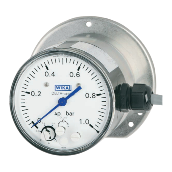
Example, model DPGS40TA with
stainless steel measuring chamber
Operating instructions
Betriebsanleitung
Mode d'emploi
Manual de instrucciones
DELTA-comb
Example, model DPGS40TA with
aluminium measuring chamber
EN
DE
FR
ES
Advertisement
Chapters
Table of Contents

Subscribe to Our Youtube Channel
Related Manuals for WIKA DPGS40TA


Summary of Contents for WIKA DPGS40TA
- Page 1 Differential pressure gauge with micro switches, model DPGS40TA, with component testing Differenzdruckmanometer mit Mikroschaltern, Typ DPGS40TA, mit Bauteilprüfung Manomètre différentiel avec microrupteurs, type DPGS40TA, avec test des composants Manómetro diferencial con microswitch, modelo DPGS40TA, con prueba de componentes DELTA-comb Example, model DPGS40TA with...
- Page 2 59 - 86 Manual de instrucciones para manómetro diferencial, modelo DPGS40TA Pagina 87 - 114 © 08/2015 WIKA Alexander Wiegand SE & Co. KG All rights reserved. / Alle Rechte vorbehalten. WIKA is a registered trademark in various countries. ®...
-
Page 3: Table Of Contents
Annex 1: DNV certificate Annex 2: SIL certificate Annex 3: TÜV certificate “Flow 100” Annex 4: Declaration of conformity, models DPS40, DPGS40, DPGS40TA 120 Annex 5: Declaration of conformity, model DPGS40TA.100-*S* Declarations of conformity can be found online at www.wika.com. -
Page 4: General Information 4 En
Explanation of symbols WARNING! ... indicates a potentially dangerous situation that can result in serious injury or death, if not avoided. Information ... points out useful tips, recommendations and information for efficient and trouble-free operation. WIKA operating instructions DPGS40TA with component testing... -
Page 5: Safety
Solely model DPGS40TA.100-*S* is suitable for operation as a flow limiter due to its TÜV certificate. See chapter 2.2 “Additional instructions for operation as a flow limiter”. -
Page 6: Additional Instructions For Operation As A Flow Limiter
2. Safety 2.2 Additional instructions for operation as a flow limiter This chapter only applies to model DPGS40TA.100-*S*. Regulations for pressure equipment Instrument type: Safety accessory ■ Media: Liquid or gaseous, group 1 (hazardous) ■ For maximum allowable pressure PS, see chapter 2.6 “Labelling, safety ■... - Page 7 Protect the instrument against coarse dirt and wide fluctua- tions in ambient temperature. 10. For sealing the connections, use flat gaskets, lens-type sealing rings or WIKA profile seals. Connections with LH-RH adjusting nut or union nut enable the positioning of the instrument for better readability.
-
Page 8: Functional Safety Of The Sil Version
2.3.2 Other applicable instrument documentation In addition to this section, the other parts of these operating instructions, 14106549, for model DPGS40TA.100-xxS, the data sheet PV 27.22 and the certificate 968/V 1169.01/21 (see Annex 2) also apply. 2.3.3 Relevant standards... - Page 9 The higher the safety integrity level of the safety-related system, the greater the probability that the safety function is executed. WIKA operating instructions DPGS40TA with component testing...
- Page 10 Number of cycles till 10 % of the components have failed dangerously Average number of operations per year β factor Factor for failure due to common causes, in terms of the interaction of several channels WIKA operating instructions DPGS40TA with component testing...
- Page 11 The safety function of the instrument is that, on falling differential pressure, the respective switch(es) will open. Use the change-over contacts so that the circuit opens on falling differential pressure (observe the closed-circuit principle). WIKA operating instructions DPGS40TA with component testing...
- Page 12 Secure the instrument against change of the switch points through the provided lead sealing of the setting ele- ments. WARNING! After each configuration procedure, check the safety function by testing it. WIKA operating instructions DPGS40TA with component testing...
- Page 13 2.3.11 Commissioning All applications Check operability of the switching function of the differential pressure gauge DPGS40TA.100-xxS during commissioning and at reasonable intervals. Both the nature of the testing as well as the chosen intervals are the responsibility of the user.
-
Page 14: Personnel Qualification
Take sufficient precautionary measures. WARNING! The maximum surface temperature of the instrument may not exceed the ignition temperature of flammable media. Take sufficient precautionary measures. WIKA operating instructions DPGS40TA with component testing... -
Page 15: Labelling, Safety Marking
3rd digit: S = SIL version Date of manufacture Pin assignment Contact type Article number Maximum allowable pressure PS per European Pressure Equipment Directive Serial number WIKA operating instructions DPGS40TA with component testing... - Page 16 Risk of burns! Potentially dangerous situation caused by hot surfaces. Due to the maximum permissible process temperature of 90 °C, measuring cells, adapters, valves or other attachment parts can reach a temperature of 90 °C. WIKA operating instructions DPGS40TA with component testing...
-
Page 17: Specifications
1.4310 and separating diaphragm from FPM/FKM (Option: NBR) Operating pressure: Bourdon tube from Cu-alloy Transmission parts Stainless steel 1.4301, 1.4305, 1.4310, FPM/FKM (wetted) (Option: NBR) Seals (wetted) FPM/FKM (Option: NBR) Movement Copper alloy WIKA operating instructions DPGS40TA with component testing... - Page 18 For further specifications, see the corresponding product label, WIKA data sheet and order documentation. For models with optional explosion protection read the “Additional information for hazardous areas (Ex i), models DPS40, DPGS40, DPGS40TA und DPGT40”, article number 14110818. WIKA operating instructions DPGS40TA with component testing...
- Page 19 1 m cable G1/4 20,5 Weight Approx. 1.4 kg [3.8 lb] With stainless steel measuring chamber Cable gland M20 x 1.5 with 1 m cable G1/4 20,5 Weight Approx. 4 kg [10.7 lb] WIKA operating instructions DPGS40TA with component testing...
-
Page 20: Design And Function
(7). The assistant scales (8) simplify the setting of the switch points. ⊖ ⊕ 4.2 Scope of delivery Cross-check scope of delivery with delivery note. WIKA operating instructions DPGS40TA with component testing... -
Page 21: Transport, Packaging And Storage
Hazardous environments, flammable atmospheres ■ WARNING! Before storing the instrument, any residual media must be removed. This is of particular importance if the medium is hazardous to health, e.g. caustic, toxic, carcinogenic, radioactive, etc. WIKA operating instructions DPGS40TA with component testing... -
Page 22: Commissioning, Operation
Protect the instrument against coarse dirt and wide fluctuations in ambient temperature. For sealing the connections, use flat gaskets, lens-type sealing rings or WIKA ■ profile seals. Connections with LH-RH adjusting nut or union nut enable the po- sitioning of the instrument for better readability. - Page 23 With gaseous substances, the temperature may increase as a result of compression warming. In these cases it may be necessary to throttle the rate of change of pressure or reduce the permissible medium temperature. WIKA operating instructions DPGS40TA with component testing...
- Page 24 (damp) densed ised Examples Conden- Boiling “Liquid Dry air Moist air Steam sate liquids gases” Flue gases Pressure gauge above the tapping point Pressure gauge below the tapping point WIKA operating instructions DPGS40TA with component testing...
-
Page 25: Electrical Connection
Rate mains connection cables for the maximum current consumption of the ■ appliance and comply with the specifications of IEC 227 or IEC 245. Include instruments in the equipotential bonding of the plant. ■ For performance data, see chapter 3 “Specifications” WIKA operating instructions DPGS40TA with component testing... - Page 26 For the safety circuit, which will switch off the heating if the steam generator falls below the minimum flow, only the normally open contact of the change-over contact should be connected (i.e. with Δp = 0 open circuit)! WIKA operating instructions DPGS40TA with component testing...
- Page 27 Seal the cable entry with the appropriate approved cable glands. ■ Cable socket design Only use cable with a diameter of 7 ... 13 mm M20 x 1.5 Install the connection cables securely. ■ WIKA operating instructions DPGS40TA with component testing...
-
Page 28: Commissioning
(with opened pressure compensating valve). Venting the measuring lines with liquid ■ media and flushing of the measuring lines, in order to remove contamination. Shut-off valve Vent valve ⊖ side WIKA operating instructions DPGS40TA with component testing... -
Page 29: Panel Mounting Flange
1. Close the shut-off valve for the ⊕ and ⊖ media chamber 2. Open the vent valve 7.2 Panel mounting flange For aluminium measuring chamber For stainless steel measuring chamber Panel Panel WIKA operating instructions DPGS40TA with component testing... -
Page 30: Maintenance
9.3 Disposal Incorrect disposal can put the environment at risk. Dispose of instrument components and packaging materials in an environmentally compatible way and in accordance with the country-specific waste disposal regulations. WIKA operating instructions DPGS40TA with component testing... - Page 31 Entsorgung ..... . . 58 Anhang 1: DNV-Zetifikat Anhang 2: SIL-Zertifikat Anhang 3: VdTÜV-Bescheinigung „Strömung 100“ Anhang 4: Konformitätserklärung, Typen DPS40, DPGS40, DPGS40TA Anhang 5: Konformitätserklärung, Typ DPGS40TA.100-*S* Konformitätserklärungen finden Sie online unter www.wika.de. WIKA-Betriebsanleitung DPGS40TA mit Bauteilprüfung...
-
Page 32: Allgemeines
… weist auf eine möglicherweise gefährliche Situation hin, die zum Tod oder zu schweren Verletzungen führen kann, wenn sie nicht gemieden wird. Information … hebt nützliche Tipps und Empfehlungen sowie Informationen für einen effizienten und störungsfreien Betrieb hervor. WIKA-Betriebsanleitung DPGS40TA mit Bauteilprüfung... -
Page 33: Sicherheit
Heizungs-, Klima-, Lüftungstechnik, Wasser-/Abwasserindustrie und Maschinen- und Anlagenbau. Hier ist die Hauptaufgabe der Messgeräte die Überwachung und Steuerung von Filtern, Kompressoren und Pumpen. Einzig Typ DPGS40TA.100-*S* ist aufgrund der TÜV-Bescheinigung als Strö- mungsbegrenzer einsetzbar. Siehe Kapitel „2.2 Zusatzhinweise für den Einsatz als Strömungsbegrenzer“. -
Page 34: Zusatzhinweise Für Den Einsatz Als Strömungsbegrenzer
2. Sicherheit 2.2 Zusatzhinweise für den Einsatz als Strömungsbegrenzer Dieses Kapitel betrifft ausschließlich Typ DPGS40TA.100-*S*. Regularien für Druckgeräte Geräteart: Ausrüstungsteil mit Sicherheitsfunktion ■ Messstoffe: Flüssig oder gasförmig, Gruppe 1 (gefährlich) ■ Maximal zulässiger Druck PS siehe Kapitel „2.6 Beschilderung, Sicherheits- ■... - Page 35 Gerät vor grober Verschmutzung und starken Schwankungen der Umge- bungstemperatur schützen. 10. Zur Abdichtung der Anschlüsse sind Flachdichtungen, Dichtlinsen oder WIKA-Profildichtungen einzusetzen. Anschlüsse mit Spannmuffe oder Überwurfmutter ermöglichen die Positionierung des Geräts zur besseren Ablesbarkeit. Zur Montage oder Demontage des Geräts darf die erforderliche Kraft nicht über das Gehäuse eingeleitet werden, sondern nur an den Schlüs-...
-
Page 36: Funktionale Sicherheit Der Sil-Ausführung
Darstellungen erläutert. 2.3.2 Mitgeltende Gerätedokumentation Ergänzend zu diesem Abschnitt gelten die anderen Teile dieser Betriebsanleitung 14106549 für Typ DPGS40TA.100-xxS, das Datenblatt PV 27.22 sowie das Zertifi- kat 968/V 1169.01/21 (siehe Anhang 2). 2.3.3 Relevante Standards... - Page 37 Integrity Level (SIL 1 bis SIL 4). Jeder Level entspricht einem Wahrscheinlichkeitsbereich mit welchem ein sicherheitsbezogenes System die festgelegten Sicherheitsfunktionen anforderungsgemäß ausführt. Je höher der Safety Integrity Level der sicherheitsbezogenen Systeme ist, umso größer die Wahrscheinlichkeit, dass die Sicherheitsfunktion ausgeführt wird. WIKA-Betriebsanleitung DPGS40TA mit Bauteilprüfung...
- Page 38 Mittlere Zeit bis zum Auftreten eines gefahrbringenden Ausfalls Anzahl von Zyklen, bis 10 % der Komponenten gefährlich ausgefallen sind Mittlere Anzahl der jährlichen Betätigungen β-Faktor Faktor für den Ausfall infolge gemeinsamer Ursachen, im Hinblick auf das Zusammenwirken mehrerer Kanäle WIKA-Betriebsanleitung DPGS40TA mit Bauteilprüfung...
- Page 39 2.3.7 Sicherheitsfunktion Die Sicherheitsfunktion des Geräts besteht darin, dass bei sinkendem Diffe- renzdruck der bzw. die Schalter geöffnet werden. Die Wechsler in einer Sicher- heitsfunktion so verwenden, dass der Stromkreis bei sinkendem Differenzdruck geöffnet wird (Ruhestromprinzip beachten). WIKA-Betriebsanleitung DPGS40TA mit Bauteilprüfung...
- Page 40 Änderung durch den Anwender überprüfen. Kennzeichnung z. B. mit einem passenden Aufkleber aktualisieren. Das Gerät gegen Änderung der Schaltpunkte durch die vorgesehene Verplombung der Einstellelemente sichern. WARNUNG! Nach jedem Konfigurationsvorgang die Sicherheitsfunktion durch einen Test prüfen. WIKA-Betriebsanleitung DPGS40TA mit Bauteilprüfung...
- Page 41 2.3.13 Hinweise zur Ermittlung sicherheitstechnischer Kenngrößen Die Ausfallraten der Geräte wurden durch Anwendung von statistischen Methoden nach IEC 61508 auf Basis einer Typprüfung für DPGS40TA.100-xxS ermittelt. Das Gerät ist vorgesehen für Anwendungen mit niedriger oder mit hoher Anforde- rungsrate.
-
Page 42: Personalqualifikation
Vorschriften beachtet werden. WARNUNG! Messstoffreste in ausgebauten Messgeräten können zur Gefähr- dung von Personen, Umwelt und Einrichtung führen. Ausreichende Vorsichtsmaßnahmen ergreifen. WARNUNG! Die maximale Oberflächentemperatur des Geräts darf die Zündtemperatur brennbarer Messstoffe nicht überschreiten. Ausreichende Vorsichtsmaßnahmen ergreifen. WIKA-Betriebsanleitung DPGS40TA mit Bauteilprüfung... -
Page 43: Beschilderung, Sicherheitskennzeichnungen
2. Stelle S = Strömungsbegrenzer, siehe Kapitel „2.2 Zusatzhinweise für den Einsatz als Strömungsbegrenzer“ 3. Stelle S = SIL-Ausführung Herstellungsdatum Anschlussbelegung Kontakttyp Artikelnummer Maximal zulässiger Druck PS nach europäischer Druckgeräterichtlinie Seriennummer WIKA-Betriebsanleitung DPGS40TA mit Bauteilprüfung... - Page 44 Vor Montage und Inbetriebnahme des Geräts unbedingt die Betriebsanleitung lesen! Verbrennungsgefahr! Möglicherweise gefährliche Situation durch heiße Oberflächen. Aufgrund der maximal zulässigen Prozesstemperatur von 90 °C können Messzellen, Anschlussstücke, Ventile oder sonstige Anbauteile eine Temperatur von 90 °C erreichen. WIKA-Betriebsanleitung DPGS40TA mit Bauteilprüfung...
-
Page 45: Technische Daten
Achsabstand 26 mm (messstoffberührt) Messglieder Differenzdruck: Druckfedern aus CrNi-Stahl 1.4310 und (messstoffberührt) Trennmembrane aus FPM/FKM (Option: NBR) Betriebsdruck: Rohrfeder aus Cu-Legierung Übertragungsteile CrNi-Stahl 1.4301, 1.4305, 1.4310, FPM/FKM (messstoffberührt) (Option: NBR) Dichtungen FPM/FKM (Option: NBR) (messstoffberührt) Kupferlegierung Zeigerwerk WIKA-Betriebsanleitung DPGS40TA mit Bauteilprüfung... - Page 46 1) I max. = 1,4 A für Ausführung nach VdTÜV Merkblatt „Strömung 100“ Weitere technische Daten siehe jeweiliges Typenschild, WIKA-Datenblatt und Bestellunterlagen. Für Typen mit optionalem Explosionsschutz „Zusatzinformation für explosionsgefährdete Bereiche (Ex i), Typen DPS40, DPGS40, DPGS40TA und DPGT40”, Artikelnummer 14110818 lesen. WIKA-Betriebsanleitung DPGS40TA mit Bauteilprüfung...
- Page 47 3. Technische Daten Abmessungen in mm Mit Aluminium-Messkammer Kabelverschraubung M20 x 1,5 mit 1 m Kabel G1/4 20,5 Mit CrNi-Stahl-Messkammer Kabelverschraubung M20 x 1,5 mit 1 m Kabel G1/4 20,5 WIKA-Betriebsanleitung DPGS40TA mit Bauteilprüfung...
-
Page 48: Aufbau Und Funktion
Stützflächen (6) erreicht. Die Schaltpunktverstellung erfolgt über die frontseitig zugänglichen Einstell- schrauben (7). Die Hilfsskalen (8) erleichtern die Schaltpunkteinstellung. ⊖ ⊕ 4.2 Lieferumfang Lieferumfang mit dem Lieferschein abgleichen. WIKA-Betriebsanleitung DPGS40TA mit Bauteilprüfung... -
Page 49: Transport, Verpackung Und Lagerung
■ Explosionsgefährdete Umgebung, entzündliche Atmosphären ■ WARNUNG! Vor der Einlagerung des Geräts müssen alle ggf. anhaftenden Messstoffreste entfernt werden. Dies ist besonders wichtig, wenn das Medium gesundheitsgefährdend ist, wie z. B. ätzend, giftig, krebserregend, radioaktiv, usw. WIKA-Betriebsanleitung DPGS40TA mit Bauteilprüfung... -
Page 50: Inbetriebnahme, Betrieb
Geräts und eine Nullpunktkontrolle bei laufender Anlage ermöglicht. Das Gerät vor grober Verschmutzung und starken Schwankungen der Umgebungstempe- ratur schützen. Zur Abdichtung der Anschlüsse sind Flachdichtungen, Dichtlinsen oder WIKA- ■ Profildichtungen einzusetzen. Anschlüsse mit Spannmuffe oder Überwurfmut- ter ermöglichen die Positionierung des Geräts zur besseren Ablesbarkeit. Zur Montage oder Demontage des Geräts darf die erforderliche Kraft nicht über... - Page 51 Die tatsächliche maximale Oberflächentemperatur ist nicht von diesen Geräten selbst abhängig, sondern hauptsächlich von der jeweiligen Messstofftemperatur! Bei gasförmigen Stoffen kann sich die Temperatur durch Kompressionswärme erhöhen. In solchen Fällen muss ggf. die Druckänderungsgeschwindigkeit gedrosselt bzw. die zulässige Messstofftemperatur reduziert werden. WIKA-Betriebsanleitung DPGS40TA mit Bauteilprüfung...
- Page 52 Zum Teil Vollständig Messleitung ausga- dig ver- förmig kondensiert konden- send dampft (feucht) siert Beispiele Kondensat Siedende „Flüssig- Trockene Feuchte Luft Wasserdampf Flüssigkei- gase“ Luft Rauchgase Manometer oberhalb des Entnahme- stutzens Manometer unterhalb des Entnah- mestutzens WIKA-Betriebsanleitung DPGS40TA mit Bauteilprüfung...
-
Page 53: Elektrischer Anschluss
Gerät angegeben und die Anschlussklemmen sind entsprechend gekennzeichnet. Netzanschlussleitungen für die größte Stromaufnahme des Geräts bemessen ■ und dabei den Vorgaben von IEC 227 oder IEC 245 entsprechen. Geräte in den Potenzialausgleich der Anlage einbeziehen. ■ Leistungsdaten siehe Kapitel 3 „Technische Daten“ WIKA-Betriebsanleitung DPGS40TA mit Bauteilprüfung... - Page 54 2. Kontakt 1. Kontakt Kabelanschlussdose Für den Sicherheitsstromkreis, der bei Unterschreiten des Min- destdurchflusses die Beheizung des Dampferzeugers abschalten soll, darf nur der Schließer des Umschaltkontakts angeschlossen werden (d.h. der bei Δp = 0 offene Kreis)! WIKA-Betriebsanleitung DPGS40TA mit Bauteilprüfung...
- Page 55 Anschlussleitungen müssen für den Umgebungstemperaturbereich der ■ Applikation geeignet sein. Kabeleinführung mit den entsprechend zugelassenen Kabelverschraubungen ■ dicht verschließen. Ausführung der Kabeldose Nur Kabel mit Durchmesser 7 ... 13 mm verwenden M20 x 1.5 Anschlusskabel fest verlegen. ■ WIKA-Betriebsanleitung DPGS40TA mit Bauteilprüfung...
-
Page 56: Inbetriebnahme
Prozess sowie Vermeidung einseitiger Überdruckbelastung während der Anfahr- bzw. Betriebsphase (bei geöffnetem Druckausgleichsventil). Entlüftung der Messleitungen bei flüssigen ■ Messstoffen und Spülung der Messleitun- Absperrventil Entlüftungs- ⊖ ventil -Seite gen, um Verunreinigungen zu entfernen. WIKA-Betriebsanleitung DPGS40TA mit Bauteilprüfung... -
Page 57: Befestigungsrand Für Schalttafelmontage
2. Absperrventil der ⊕- und ⊖-Messstoffraum schließen Arbeitsgangfolge zur Demontage des Messgeräts bei laufenden Prozess ■ 1. Absperrventil der ⊕- und ⊖-Messstoffraum schließen 2. Entlüftungsventil öffnen 7.2 Befestigungsrand für Schalttafelmontage Für Aluminium-Messkammer Für CrNi-Stahl-Messkammer Schalttafel Schalttafel WIKA-Betriebsanleitung DPGS40TA mit Bauteilprüfung... -
Page 58: Wartung
Ausgebautes Messgerät vor der Rücksendung spülen bzw. säubern, um Mitarbeiter und Umwelt vor Gefährdung durch anhaftende Messstoffreste zu schützen. 9.3 Entsorgung Durch falsche Entsorgung können Gefahren für die Umwelt entstehen. Gerätekomponenten und Verpackungsmaterialien entsprechend den landesspezifischen Abfallbehandlungs- und Entsorgungsvorschriften umweltgerecht entsorgen. WIKA-Betriebsanleitung DPGS40TA mit Bauteilprüfung... - Page 59 Annexe 1 : Certificat DNV Annexe 2 : Certificat SIL Annexe 3 : Certificat TÜV (contrôle technique allemand) “Flux 100” Annexe 4 : Déclaration de conformité, types DPS40, DPGS40, DPGS40TA Annexe 5 : Déclaration de conformité, type DPGS40TA.100-*S* Déclarations de conformité disponibles sur www.wika.fr.
-
Page 60: Généralités
évitée. Information … met en exergue des conseils et recommandations utiles de même que des informations permettant d'assurer un fonctionne- ment efficace et normal. WIKA mode d'emploi DPGS40TA avec test de composants... -
Page 61: Sécurité
Pour celles-ci, la fonction principale des instruments de mesure est la surveillance de filtres, de compresseurs et de pompes. Seul le type DPGS40TA.100-*S* peut être utilisé comme limiteur de flux grâce à son certificat TÜV. Voir chapitre 2.2 “Instructions complémentaires pour une utilisa- tion comme limiteur de flux”. -
Page 62: Instructions Complémentaires Pour Une Utilisation Comme Limiteur De Flux
Se conformer aux règles techniques générales pour les instruments de me- sure de pression (par exemple EN 837-2 “Recommandations sur le choix et l'installation des manomètres”). WIKA mode d'emploi DPGS40TA avec test de composants... - Page 63 10. Pour sceller les connexions, utiliser des joints d'étanchéité plats, des bagues d'étanchéité de type lentille ou des joints à écrasement WIKA. Les raccords avec écrou de réglage gauche/droit ou écrou-chapeau permettent de posi- tionner l’instrument pour une meilleure lisibilité.
-
Page 64: Sécurité Fonctionnelle De La Version Sil
2.3.2 Autre documentation d'instrument applicable En plus de cette section, les autres parties de ce mode d'emploi, 14106549, pour le type DPGS40TA.100-xxS, la fiche technique PV 27.22 et le certificat 968/V 1169.01/21 (voir annexe 2) s'appliquent également. 2.3.3 Normes pertinentes... - Page 65 Pourcentage d'erreurs conduisant à un danger qui sont détectées par des tests de diagnostic en ligne automatiques. Tolérance d'erreur matériel Capacité d'une unité fonctionnelle à continuer l'exécution de la fonction demandée lorsque des erreurs ou des déviations se produisent. WIKA mode d'emploi DPGS40TA avec test de composants...
- Page 66 Nombre de cycles avant que 10 % des composants aient failli de manière dangereuse Nombre moyen d'opérations par an Facteur β Facteur pour une erreur due à des causes courantes, en termes d'interaction de plusieurs canaux WIKA mode d'emploi DPGS40TA avec test de composants...
- Page 67 La fonction de sécurité de l'instrument fait que, dans le cas d'une pression diffé- rentielle en baisse, les commutateurs respectifs vont s'ouvrir. Utiliser les contacts inverseurs de sorte que le circuit s'ouvre sur une pression différentielle en baisse (observer le principe de circuit fermé). WIKA mode d'emploi DPGS40TA avec test de composants...
- Page 68 Mettre à jour le marquage, par exemple à l’aide d’un autocollant approprié. Protéger l'instrument contre les modifications des points de seuil, par le plombage des éléments de réglage. AVERTISSEMENT ! Après chaque procédure de configuration, vérifier la fonction de sécurité en la testant. WIKA mode d'emploi DPGS40TA avec test de composants...
- Page 69 Toutes applications Vérifier le fonctionnement de la fonction de commutation du manomètre diffé- rentiel DPGS40TA.100-xxS lors de la mise en service et à intervalles réguliers raisonnables. La nature du contrôle ainsi que les intervalles choisis sont de la responsabilité de l'utilisateur.
-
Page 70: Qualification Du Personnel
Prendre des mesures de sécurité suffisantes. AVERTISSEMENT ! La température de surface maximum admissible de l'instrument ne doit pas dépasser la température d'inflammation de fluides inflammables. Prendre des mesures de sécurité suffisantes. WIKA mode d'emploi DPGS40TA avec test de composants... -
Page 71: Etiquetage, Marquages De Sécurité
Date de fabrication Configuration du raccordement Type de contact Numéro d'article Pression maximale admissible PS selon la directive européenne relative aux équipe- ments sous pression Numéro de série WIKA mode d'emploi DPGS40TA avec test de composants... - Page 72 Situation présentant des risques dues à des surfaces chaudes. En raison de la température de process maximum admissible de 90 °C, les cellules de mesure, adaptateurs, robinets ou autres élé- ments de montage peuvent atteindre des températures de 90 °C. WIKA mode d'emploi DPGS40TA avec test de composants...
-
Page 73: Spécifications
1.4310 et membrane de séparation en FPM/FKM avec le fluide) (option : NBR) Pression de fonctionnement : tube manométrique en alliage de cuivre Pièces de transmission Acier inox 1.4301, 1.4305, 1.4310, FPM/FKM (contact avec fluide) (option : NBR) WIKA mode d'emploi DPGS40TA avec test de composants... - Page 74 1) I max. = 1,4 A pour des versions en accord avec le code de pratique VdTÜV “Flux 100” Pour de plus amples spécifications, voir la plaque signalétique correspondante, la fiche technique WIKA et la documentation de commande. Pour les types avec protection contre les explosions, lire les “Informations complémentaires concernant les zones explosives (Ex i), types DPS40, DPGS40,...
- Page 75 G1/4 20,5 Poids Environ 1,4 kg [3,8 lb] Avec chambre de mesure en acier inox Presse-étoupe M20 x 1,5 avec 1 m de câble G1/4 20,5 Poids Environ 4 kg [10,7 lb] WIKA mode d'emploi DPGS40TA avec test de composants...
-
Page 76: Conception Et Fonction
(7). Les échelles auxiliaires (8) facilitent le réglage des points de seuil. ⊖ ⊕ 4.2 Détail de la livraison Comparer le détail de la livraison avec le bordereau de livraison. WIKA mode d'emploi DPGS40TA avec test de composants... -
Page 77: Transport, Emballage Et Stockage
Enlever tous les restes de fluides adhérents avant l'entreposage de l'instrument. Cela est particulièrement important lorsque le fluide représente un danger pour la santé, p. ex. des substances corrosives, toxiques, cancérogènes, radioactives etc. WIKA mode d'emploi DPGS40TA avec test de composants... -
Page 78: Mise En Service, Utilisation
Pour sceller les connexions, utiliser des joints d'étanchéité plats, des bagues ■ d'étanchéité de type lentille ou des joints à écrasement WIKA. Les raccords avec écrou de réglage gauche/droit ou écrou-chapeau permettent de position- ner l’instrument pour une meilleure lisibilité. Pour le montage ou le démontage de l’instrument, la force nécessaire ne doit pas être exercée via le boîtier, mais... - Page 79 Avec les substances gazeuses, la température pourrait augmenter à la suite d'un échauffement de compression. Dans ces cas-là, il peut s'avérer nécessaire d'accélérer le taux de changement de pression ou de réduire la température du fluide admissible. WIKA mode d'emploi DPGS40TA avec test de composants...
- Page 80 (humide) Exemples Conden- Liquides “Gaz Air sec Air humide Vapeur bouillants liquéfiés” gaz de combustion Manomètre au-dessus du point de mesure Manomètre en-dessous du point de mesure WIKA mode d'emploi DPGS40TA avec test de composants...
-
Page 81: Raccordement Électrique
CEI 227 ou CEI 245. Inclure les instruments dans la liaison équipotentielle de l'installation. ■ Pour les données de performance, voir chapitre 3 “Spécifications” WIKA mode d'emploi DPGS40TA avec test de composants... - Page 82 Pour le circuit de sécurité, qui va éteindre le chauffage si le gé- nérateur de vapeur tombe sous la valeur minimum de flux, seul le contact normalement ouvert du contact inverseur doit être raccor- dé (c'est-à-dire avec Δp = 0 circuit ouvert) ! WIKA mode d'emploi DPGS40TA avec test de composants...
- Page 83 Sceller l'entrée de câble avec les presse-étoupes homologués adéquats. ■ Conception de boîtier de raccordement Utiliser seulement un câble ayant un diamètre de 7 ... 13 mm M20 x 1.5 Installer les câbles de raccordement en toute sécurité. ■ WIKA mode d'emploi DPGS40TA avec test de composants...
-
Page 84: Mise En Service
Robinet Robinet Mise à l'atmosphère des lignes de mesure ■ d’isolement de mise à avec des fluides liquides et un rinçage côté ⊖ l'atmosphère des lignes de mesure pour supprimer la contamination. WIKA mode d'emploi DPGS40TA avec test de composants... -
Page 85: Collerette Avant Pour Montage Panneau
1. Fermer le robinet d’isolement pour les chambres de fluide ⊕ et ⊖ 2. Ouvrir la soupape de mise à l'atmosphère 7.2 Collerette avant pour montage panneau Pour chambre de mesure en aluminium Pour chambre de mesure en acier inox Panneau Panneau WIKA mode d'emploi DPGS40TA avec test de composants... -
Page 86: Entretien
Une mise au rebut inadéquate peut entraîner des dangers pour l'environnement. Eliminer les composants des instruments et les matériaux d'emballage conformément aux prescriptions nationales pour le traitement et l'élimination des déchets et aux lois de protection de l'environnement en vigueur. WIKA mode d'emploi DPGS40TA avec test de composants... - Page 87 Anexo 1: Certificado DNV Anexo 2: Certificado SIL Anexo 3: Certificado TÜV “Caudal 100” Anexo 4: Declaración de conformidad, modelos DPS40, DPGS40, DPGS40TA 120 Anexo 5: Declaración de conformidad, modelo DPGS40TA.100-*S* Declaraciones de conformidad puede encontrar en www.wika.es. WIKA manual de instrucciones DPGS40TA con prueba de componentes...
-
Page 88: Información General
... señala una situación potencialmente peligrosa que puede cau- sar la muerte o lesiones graves si no se evita. Información ... destaca consejos y recomendaciones útiles así como informa- ciones para una utilización eficiente y libre de errores. WIKA manual de instrucciones DPGS40TA con prueba de componentes... -
Page 89: Seguridad
La tarea principal de los instrumentos de medición en estas aplica- ciones consiste en la monitorización y el control de filtros, compresores y bombas. Solamente el modelo DPGS40TA.100-*S* puede utilizarse como limitador de caudal gracias a que dispone de la certificación TÜV correspondiente. Véase el capítulo 2.2 “Instrucciones adicionales para el funcionamiento como limitador de... -
Page 90: Instrucciones Adicionales Para El Funcionamiento Como Limitador De Caudal
Conforme a las reglas técnicas generales para manómetros (por ejemplo EN 837-2 “Recomendaciones relativas a la selección y montaje de manóme- tros”). WIKA manual de instrucciones DPGS40TA con prueba de componentes... - Page 91 10. Para sellar las conexiones deben utilizarse juntas planas, juntas lenticula- res o juntas perfiladas WIKA. El uso de conexiones con tuerca de ajuste a izquierdas-derechas o tuerca loca permiten posicionar el instrumento para una lectura óptima. Para el montaje o el desmontaje del instrumento, la fuerza necesaria no se debe aplicar en la carcasa, sino en los planos de llave de la conexión.
-
Page 92: Seguridad Funcional De La Versión Sil
2.3.2 "Otra documentación de los instrumentos aplicable". El manual de instrucciones proporciona indicaciones importantes acerca del ma- nejo del manómetro de presión diferencial DPGS40TA.100-xxS. Para un trabajo seguro, es imprescindible cumplir con todas las instrucciones de seguridad y manejo indicadas. - Page 93 Cuanto mayor sea el nivel de integridad de los sistemas de seguridad, mayor es la probabilidad de que se ejecute la función de seguridad. WIKA manual de instrucciones DPGS40TA con prueba de componentes...
- Page 94 Cantidad de ciclos hasta que un 10% de los componentes presentan un fallo peligroso Promedio de operaciones por año Factor β Factor para el fallo como resultado de causas conjuntas, respecto a la interacción de varios canales WIKA manual de instrucciones DPGS40TA con prueba de componentes...
- Page 95 La función de seguridad hace que con una presión diferencial descendente se abren los interruptores. Utilice los contactos conmutados de tal manera que el circuito de corriente se abra con una presión diferencial descendente (observar el principio de corriente de reposo). WIKA manual de instrucciones DPGS40TA con prueba de componentes...
- Page 96 ¡ADVERTENCIA! Verifique la función de seguridad después de cada procedimiento probándola. 2.3.11 Puesta en servicio WIKA manual de instrucciones DPGS40TA con prueba de componentes...
- Page 97 Todas aplicaciones Compruebe la capacidad de funcionamiento de la función de conmutación del manómetro diferencial DPGS40TA.100-xxS durante la puesta en servicio, así como a intervalos regulares. El usuario es responsable de especificar tanto el tipo de prueba como los intervalos.
-
Page 98: Cualificación Del Personal
Tomar las medidas de precaución adecuadas. ¡ADVERTENCIA! La temperatura máxima de la superficie del instrumento no debe ser superior a la temperatura de ignición de medios inflamables. Tomar las medidas de precaución adecuadas. WIKA manual de instrucciones DPGS40TA con prueba de componentes... -
Page 99: Rótulos / Marcajes De Seguridad
Fecha de fabricación Detalles del conexionado Tipo de contacto Código Presión máxima admisible PS según la Directiva Europea de Equipos a Presión Número de serie WIKA manual de instrucciones DPGS40TA con prueba de componentes... - Page 100 Debido a una temperatura de proceso máx. admisible de 90 °C, las células de medida, los racores, las válvulas o otras piezas de montaje pueden alcanzar una temperatura de 90 °C. WIKA manual de instrucciones DPGS40TA con prueba de componentes...
-
Page 101: Datos Técnicos Es
(en contacto con el medio) (opción: NBR) Presión de trabajo: Muelle tubular de aleación de cobre Piezas de transmisión Acero inoxidable 1.4301, 1.4305, 1.4310, FPM/FKM (en contacto con el (opción: NBR) medio) WIKA manual de instrucciones DPGS40TA con prueba de componentes... - Page 102 1) I máx. = 1,4 A para versiones según el código de prácticas de VdTÜV "Caudal 100" Para consultar más datos técnicos véase la placa de identificación correspondiente, la hoja técnica de WIKA y la documentación de pedido. Para los modelos con protección opcional contra explosiones, lea la "Información adicional para zonas potencialmente explosivas (Ex i), modelos DPS40, DPGS40, DPGS40TA y DPGT40", código 14110818.
- Page 103 20,5 Peso Approx. 1,4 kg [3,8 lb] Con cámara de medición de acero inoxidable Prensaestopa M20 x 1,5 con 1 m de cable G1/4 20,5 Peso Approx. 4 kg [10,7 lb] WIKA manual de instrucciones DPGS40TA con prueba de componentes...
-
Page 104: Diseño Y Función
Las escalas auxiliares (8) facilitan el ajuste de los puntos de conmutación. ⊖ ⊕ 4.2 Alcance del suministro Comparar mediante el albarán si se han entregado todas las piezas. WIKA manual de instrucciones DPGS40TA con prueba de componentes... -
Page 105: Transporte, Embalaje Y Almacenamiento
Antes de almacenar el instrumento, eliminar todos los restos de medios adheridos. Esto es especialmente importante cuando el medio es nocivo para la salud, como p. ej. cáustico, tóxico, cancerígeno, radioactivo, etc. WIKA manual de instrucciones DPGS40TA con prueba de componentes... -
Page 106: Puesta En Servicio, Funcionamiento
Para sellar las conexiones deben utilizarse juntas planas, juntas lenticulares o ■ juntas perfiladas WIKA. El uso de conexiones con tuerca de ajuste a izquier- das-derechas o tuerca loca permiten posicionar el instrumento para una lectura óptima. Para el montaje o el desmontaje del instrumento, la fuerza necesaria no se debe aplicar en la carcasa, sino en los planos de llave de la conexión. - Page 107 En estos casos, hay que disminuir la velocidad de cambio de presión o reducir la temperatura admisible del medio si fuera necesario. WIKA manual de instrucciones DPGS40TA con prueba de componentes...
- Page 108 Ejemplos Conden- Líquidos “Gases Aire seco Aire húmedo Vapor de sado líquidos” Gases de agua ebullición combustión Manómetro por encima del punto de medida Manómetro por debajo del punto de medida WIKA manual de instrucciones DPGS40TA con prueba de componentes...
-
Page 109: Conexión Eléctrica
IEC 227 o IEC 245. Integrar los instrumentos en la conexión equipotencial de la instalación. ■ Información de rendimiento, véase el capítulo 3 “Datos técnicos” WIKA manual de instrucciones DPGS40TA con prueba de componentes... - Page 110 (es decir, el circuito abierto en Δp = 0)! WIKA manual de instrucciones DPGS40TA con prueba de componentes...
- Page 111 Sellar las entradas de cable con prensaestopas debidamente aprobados. ■ Diseño de la caja de conexiones Utilizar únicamente cables de diámetro 7 ... 13 mm M20 x 1.5 Instalar el cable de conexión de forma segura. ■ WIKA manual de instrucciones DPGS40TA con prueba de componentes...
-
Page 112: Puesta En Servicio
Válvula de Válvula de cierre, lado ⊖ ventilación Purgado de las tuberías de medición en ■ medios líquidos y enjuague de las mismas para eliminar impurezas. WIKA manual de instrucciones DPGS40TA con prueba de componentes... -
Page 113: Borde Frontal
1. Cerrar la válvula de cierre de las cámaras del medio ⊕ y ⊖ 2. Abrir la válvula de ventilación 7.2 Borde frontal Para cámara de medición de aluminio Para cámara de medición de acero inoxidable Panel Panel WIKA manual de instrucciones DPGS40TA con prueba de componentes... -
Page 114: Mantenimiento
Una eliminación incorrecta puede provocar peligros para el medio ambiente. Eliminar los componentes de los instrumentos y los materiales de embalaje conforme a los reglamentos relativos al tratamiento de residuos y eliminación vigentes en el país de utilización. WIKA manual de instrucciones DPGS40TA con prueba de componentes... - Page 115 (including negligence), shall be limited to direct losses and under any circumstance be limited to 300,000 USD. Form code: TA 251 Revision: 2021-03 www.dnv.com Page 1 of 2 WIKA operating instructions DPGS40TA with component testing...
- Page 116 Type Approval are complied with. Refer to the Class Programme DNV-CP-0338, Sec.4. To check the validity of this certificate, please look it up in https://approvalfinder.dnv.com Form code: TA 251 Revision: 2021-03 www.dnv.com Page 2 of 2 WIKA operating instructions DPGS40TA with component testing...
- Page 117 Annex 2: SIL certificate WIKA operating instructions DPGS40TA with component testing...
- Page 118 Annex 2: SIL certificate WIKA operating instructions DPGS40TA with component testing...
- Page 119 Annex 3: VdTÜV certificate “Flow 100” Ingo Blohm 2022.06.10 11:35:32 +02'00' WIKA operating instructions DPGS40TA with component testing...
- Page 120 Annex 4: Declaration of conformity, models DPS40, DPGS40, DPGS40TA WIKA operating instructions DPGS40TA with component testing...
- Page 121 Annex 4: Declaration of conformity, models DPS40, DPGS40, DPGS40TA WIKA operating instructions DPGS40TA with component testing...
- Page 122 Annex 5: Declaration of conformity, model DPGS40TA.100-*S* WIKA operating instructions DPGS40TA with component testing...
- Page 123 Annex 5: Declaration of conformity, model DPGS40TA.100-*S* WIKA operating instructions DPGS40TA with component testing...
- Page 124 WIKA-Niederlassungen weltweit finden Sie online unter www.wika.de. La liste des filiales WIKA dans le monde se trouve sur www.wika.fr. La lista de las sucursales WIKA en el mundo puede consultarse en www.wika.es. Importer for UK WIKA Alexander Wiegand SE & Co. KG WIKA Instruments Ltd Alexander-Wiegand-Straße 30...
Need help?
Do you have a question about the DPGS40TA and is the answer not in the manual?
Questions and answers