Table of Contents
Advertisement
Available languages
Available languages
Advertisement
Chapters
Table of Contents

Related Manuals for WIKA DIH50


Summary of Contents for WIKA DIH50
- Page 1 Operating instructions Betriebsanleitung Field indicator for current loops with HART communication ® Models DIH50, DIH52 Feldanzeige für Stromschleifen mit HART ® -Kommunikation Typen DIH50, DIH52 Field display models DIH5x-F, DIH5x-I, DIH5x-S...
- Page 2 3 - 32 Betriebsanleitung Typen DIH50, DIH52 Seite 33 - 59 Further languages can be found at www.wika.com. © 05/2011 WIKA Alexander Wiegand SE & Co. KG All rights reserved. / Alle Rechte vorbehalten. WIKA is a registered trademark in various countries.
-
Page 3: Table Of Contents
12. Dismounting, return and disposal Appendix 1: EU declaration of conformity Appendix 2: FM/CSA installation drawing Appendix 3: ATEX/IECEx installation drawing Appendix 4: Manufacturer's statement Declarations of conformity can be found online at www.wika.com. WIKA operating instructions models DIH50, DIH52... -
Page 4: General Information
... indicates a potentially dangerous situation which can result in light injuries or damage to the equipment or the environment if not avoided. Information ... points out useful tips, recommendations and information for efficient and trouble-free operation. WIKA operating instructions models DIH50, DIH52... -
Page 5: Safety
2.1 Intended use The field indicators models DIH50, DIH52 are used for converting an analogue current signal (4 … 20 mA) into an indication of the corresponding measured value and are intended for mounting in the field. - Page 6 Repairs are strictly prohibited. ■ Do not use displays presenting externally visible damage. ■ Observe the instructions for mounting and operation as well as the ■ requirements for the use of the devices in hazardous areas. WIKA operating instructions models DIH50, DIH52...
- Page 7 WARNING! Residual media in the dismounted instrument can result in a risk to persons, the environment and equipment. Take sufficient precautionary measures. WIKA operating instructions models DIH50, DIH52...
- Page 8 DIH50-B XXXXXXXX 2016 4 ... 20 mA 2-wire HART ® Made in Germany WIKA Alexander Wiegand SE & Co. KG D-63911 Klingenberg DIH50-B XXXXXXXX 2016 4 ... 20 mA HART 2-wire ® Made in BVS 16 ATEX E 112 X IS, CL 1, DIV 1, Grp.
-
Page 9: Specifications
1) Special version on request (only available with selected approvals) 2) In previous ambient temperatures < -20 °C a delayed recovery of the indication function could be expected, especially in case of low loop current. WIKA operating instructions models DIH50, DIH52... -
Page 10: Design And Function
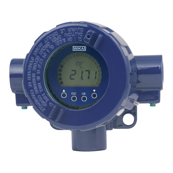
80 g see drawing Dimensions For further specifications see WIKA data sheet AC 80.10 and the order documentation. For further important safety instructions for operation in hazardous areas, see chapter 9 “Information on mounting and operation in hazardous areas”. - Page 11 HART master ® 4.1.1 Basic module (DIH50-B, DIH50-Z, DIH52-B, DIH52-Z) The basic modules comprise a mounting adapter with two integrated connection terminals and connecting cables, as well as a display unit including the display and the electronics. Both parts are connected via a cable with plug-in coupling. Depending on their design, the basic modules can be mounted in different cases or thermometer connection heads.
-
Page 12: Transport, Packaging And Storage
Keep the packaging as it will provide optimum protection during transport (e.g. change in installation site, sending for repair). 5.3 Storage Permissible conditions at the place of storage: Storage temperature: -40 ... +85 °C ■ Humidity: 35 ... 85 % relative humidity (without condensation) ■ WIKA operating instructions models DIH50, DIH52... -
Page 13: Commissioning, Operation
® configured data of the transmitter, requires a HART ® communication between the transmitter and the HART software (e.g. WIKA_T32) or between the ® transmitter and the field communicator (e.g. FC375/FC475, MFC4150 etc.). WIKA operating instructions models DIH50, DIH52... - Page 14 The devices function as secondary master with respect to the sensor during the parameterisation. 6.1.4 Operating mode: Basic mode, 4 ... 20 mA (models DIH50, DIH52) In the basic mode, all settings of the digital indicator must be carried out manually by means of the front-side keys.
-
Page 15: Electrical Connection
Connect the cable screen on both sides to earth potential if a screened cable is required. Connect the screen in the sensor directly to the internal earth terminal. The external earth terminal of the case must be connected with low impedance to the equipotential bonding. WIKA operating instructions models DIH50, DIH52... - Page 16 The connected wires must be checked to ensure they are connected properly. Only well-secured wires can guarantee a fault-free operation. Recommended tools for terminal screws: Model Screwdriver Tightening torque DIH50, Cross head ('Pozidriv' tip) 0.4 Nm size 2 (ISO 8764) DIH52 WIKA operating instructions models DIH50, DIH52...
-
Page 17: Menu Guidance
Display Unit Unit lock Display format Filter on/off Alarm Low alarm High alarm Min/Max memory delete display yes/no Configuration Language Contrast Reset User unit Min. failure message Max. failure message Firmware version Password Logout WIKA operating instructions models DIH50, DIH52... - Page 18 Adress (only DIH52) Setting the HART address of the assigned transmitter in the multidrop mode; ® for the standard current loop mode, this address must always be set to 0. Setting range: 0 ... 15 WIKA operating instructions models DIH50, DIH52...
- Page 19 From this menu item it is possible to branch into the submenu 2 for the alarm configuration by selecting SELECT. Min/Max memory ----- From this menu item it is possible to branch into the submenu 2 for the min./ max. memory by selecting SELECT. WIKA operating instructions models DIH50, DIH52...
- Page 20 (display time 5 s), the minimum value and the maximum value (display time 2 s). For the display of the maximum values, the unit on the display is replaced by min. or max. Setting range: - OFF - ON WIKA operating instructions models DIH50, DIH52...
- Page 21 The max. failure message is displayed with 5 upper scores (_ _ _ _ _) and the message OUTMAX. Setting range: 20.1 ... 21.5 mA Firmware version ----- The number of the firmware version used is displayed. WIKA operating instructions models DIH50, DIH52...
-
Page 22: Information On Mounting And Operation In Hazardous Areas
14.5 ... 42 V DIHxx-Z without -20 ... +85 °C 14.5 ... 42 V DIH50-B BVS 16 ATEX E 112 X -40 ... +85 °C at T4 < 29 V 14.5 ... 29 V IECEx BVS 16.0075X -40 ... +75 °C at T5 <... - Page 23 = 12 nF Class I, Division 2, Groups A, B, C, D = 2.2 μH NI/I/2/ABCD/T* + NI/I/2/IIC/T* DIH50-B EAC ( ТС RU C-DE.ГБ08.02128 ) /-40 ... +85 °C at T4 = 29 V 14.5 ... 29 V /-40 ... +75 °C at T5 <...
- Page 24 (4 ... 20 mA loop; terminal ⊕ and ⊖) Parameters Models DIH5x-B, DIH5x-I Voltage U 29 V Strenght of current I 100 mA Power P 680 mW Effective internal capacitance C 13.2 nF Effective internal inductance L 1.2 μH WIKA operating instructions models DIH50, DIH52...
-
Page 25: Maintenance And Cleaning
3) Special version on request (only available with selected approvals) 4) Special version 9.4 Specific conditions for safe use, models DIH50-F, DIH52-F Cables, insertions and blind plugs must be suitable for the corresponding operating temperature. You must therefore check in the application case (e.g. ambient temperature plus 5 K) whether the components used are suitable. -
Page 26: Faults
The value is outside the range supported by ■ the sensor The desired unit of measure is not supported ■ Unspecified error of the The sensor signals an error in the status byte that transmitter is not broken down WIKA operating instructions models DIH50, DIH52... -
Page 27: Dismounting, Return And Disposal
WARNING! Absolutely observe the following when shipping the instrument: All instruments delivered to WIKA must be free from any kind of hazardous substances (acids, leachate, solutions, etc.). When returning the instrument, use the original packaging or a suitable transport package. -
Page 28: Appendix 1: Eu Declaration Of Conformity
Appendix 1: EU declaration of conformity WIKA operating instructions models DIH50, DIH52... -
Page 29: Appendix 2: Fm/Csa Installation Drawing
Appendix 2: FM/CSA installation drawing WIKA operating instructions models DIH50, DIH52... -
Page 30: Appendix 3: Atex/Iecex Installation Drawing
Appendix 3: ATEX/IECEx installation drawing WIKA operating instructions models DIH50, DIH52... -
Page 31: Appendix 4: Manufacturer's Statement
Appendix 4: Manufacturer's statement WIKA operating instructions models DIH50, DIH52... - Page 32 WIKA operating instructions models DIH50, DIH52...
- Page 33 9. Hinweise zu Montage und Betrieb im explosionsgefährdeten Bereich 10. Wartung und Reinigung 11. Störungen 12. Demontage, Rücksendung und Entsorgung Anlage 1: EU-Konformitätserklärung Anlage 2: Installation drawing FM/CSA Anlage 3: Installation drawing ATEX/IECEx Anlage 4: Herstelleraussage Konformitätserklärungen finden Sie online unter www.wika.de. WIKA Betriebsanleitung Typen DIH50, DIH52...
-
Page 34: Allgemeines De
... weist auf eine möglicherweise gefährliche Situation hin, die zu geringfügigen oder leichten Verletzungen bzw. Sach- und Umweltschäden führen kann, wenn sie nicht gemieden wird. Information ... hebt nützliche Tipps und Empfehlungen sowie Informationen für einen effizienten und störungsfreien Betrieb hervor. WIKA Betriebsanleitung Typen DIH50, DIH52... -
Page 35: Sicherheit
Weitere wichtige Sicherheitshinweise befinden sich in den einzelnen Kapiteln dieser Betriebsanleitung. 2.1 Bestimmungsgemäße Verwendung Die Feldanzeigen Typen DIH50, DIH52 dienen der Umwandlung eines analogen Strom- signals (4 … 20 mA) in eine Anzeige des entsprechenden Messwertes und sind zur Montage im Feld bestimmt. - Page 36 Äußerlich beschädigte Feldanzeige nicht verwenden! VORSICHT! Reparaturen sind grundsätzlich verboten. ■ Anzeigen mit äußerlichen Beschädigungen nicht verwenden. ■ Hinweise zur Montage und zum Betrieb beachten, ebenso die Vorschriften für ■ den Einsatz von Geräten in Ex-Bereichen. WIKA Betriebsanleitung Typen DIH50, DIH52...
- Page 37 Bei Betrieb mit einem defekten Netzgerät (z. B. Kurzschluss von Netzspan- ■ nung zur Ausgangsspannung) können am Gerät lebensgefährliche Spannun- gen auftreten! WARNUNG! Messstoffreste im ausgebauten Gerät können zur Gefährdung von Personen, Umwelt und Einrichtung führen. Ausreichende Vorsichtsmaßnahmen ergreifen. WIKA Betriebsanleitung Typen DIH50, DIH52...
- Page 38 DIH50-B XXXXXXXX 2016 4 ... 20 mA 2-wire HART ® Made in Germany WIKA Alexander Wiegand SE & Co. KG D-63911 Klingenberg DIH50-B XXXXXXXX 2016 4 ... 20 mA HART 2-wire ® Made in BVS 16 ATEX E 112 X IS, CL 1, DIV 1, Grp.
-
Page 39: Technische Daten
30 g nach EN 60068-2-27 1) Sonderausführung auf Anfrage (nur mit ausgewählten Zulassungen verfügbar) 2) Bei vorangegangenen Umgebungstemperaturen < -20 °C ist mit einer zeitlich verzögerten Wideraufnahme der Anzeige- funktion zu rechnen, insbesondere bei geringem Schleifenstrom. WIKA Betriebsanleitung Typen DIH50, DIH52... -
Page 40: Aufbau Und Funktion
Gewicht ca. 80 g siehe Zeichnung Abmessungen Weitere technische Daten siehe WIKA-Datenblatt AC 80.10 und Bestellunterlagen. Weitere wichtige Sicherheitshinweise für den Betrieb in explosionsgefährdeten Bereichen siehe Kapitel 9 „Hinweise zu Montage und Betrieb im explosionsge- fährdeten Bereich“. 4. Aufbau und Funktion 4.1 4.1 Beschreibung... - Page 41 HART -Master ® 4.1.1 Basismodule (DIH50-B, DIH50-Z, DIH52-B, DIH52-Z) Die Basismodule bestehen aus einem Montageadapter mit jeweils zwei integrierten Anschlussklemmen und Anschlusskabeln, sowie einer Anzeigeeinheit mit dem Anzeige- display und Elektronik. Beide Teile sind über ein Kabel mit Steckkupplung miteinander verbunden.
-
Page 42: Transport, Verpackung Und Lagerung
Die Verpackung aufbewahren, denn diese bietet bei einem Transport einen optimalen Schutz (z. B. wechselnder Einbauort, Reparatursendung). 5.3 Lagerung Zulässige Bedingungen am Lagerort: Lagertemperatur: -40 ... +85 °C ■ Feuchtigkeit: 35 ... 85 % relative Feuchte (ohne Betauung) ■ WIKA Betriebsanleitung Typen DIH50, DIH52... -
Page 43: Inbetriebnahme, Betrieb
-Funktion, d.h. die automatische Anpassung der Anzeige auf ® die konfigurierten Daten des Transmitters, ist eine HART -Kommunikation ® zwischen Transmitter und HART -Software (z. B. WIKA_T32) oder zwischen ® Transmitter und Fieldcommunicator (z. B. FC375/FC475, MFC4150 etc.) zwingend notwendig. WIKA Betriebsanleitung Typen DIH50, DIH52... - Page 44 Leitsystem angefordert werden. Die Geräte arbeiten während der Parametrie- rung als Secondary Master gegenüber dem Sensor. 6.1.4 Betriebsart: Basismodus, 4 ... 20 mA (Typen DIH50, DIH52) Im Basismodus müssen alle Einstellungen der Digitalanzeige von Hand, mittels der front- seitigen Tasten, vorgenommen werden.
-
Page 45: Elektrischer Anschluss
Den Kabelschirm beidseitig auf Erdpotenzial legen, wenn ein geschirmtes Kabel notwen- dig ist. Den Schirm im Sensor direkt an die innere Erdungsklemme anschließen. Die äußere Erdungsklemme am Gehäuse muss niederimpedant mit dem Potenzialausgleich verbunden sein. WIKA Betriebsanleitung Typen DIH50, DIH52... - Page 46 Explosionsschutz: 30 V Die angeschlossenen Drähte auf festen Sitz kontrollieren. Nur fest angeschlossene Leitun- gen gewährleisten eine volle Funktionalität. Empfohlenes Werkzeug für Schraubklemmen: Schraubendreher Anzugsdrehmoment DIH50, Kreuzschlitz (Pozidriv-Spitze) 0,4 Nm Größe 2 (ISO 8764) DIH52 WIKA Betriebsanleitung Typen DIH50, DIH52...
-
Page 47: Menüführung
Messbereich Anfang Messbereich Ende Messbereich Format Spanne Nullpunkt Dämpfung Adresse Anzeige Einheit Einheitensperre Anzeige Format Filter Ein/Aus Alarm Min-Alarm Max-Alarm Min/Max-Wert Speicher löschen anzeigen ja/nein Konfiguration Sprache Kontrast Reset User-Einheit Min-Ausfallmeldung Max-Ausfallmeldung Firmware-Version Passwort Logout WIKA Betriebsanleitung Typen DIH50, DIH52... - Page 48 Integrationszeit zur Dämpfung des Messwertes eingeben. Einstellbereich: 0.0 … 999 Adresse (nur DIH52) Einstellung der HART -Adresse des zugeordneten Messumformers im Multidrop- ® Betrieb; Bei Standard-Stromschleifenbetrieb muss diese Adresse immer auf 0 eingestellt sein. Einstellbereich: 0 … 15 WIKA Betriebsanleitung Typen DIH50, DIH52...
- Page 49 Von diesem Menüpunkt aus wird, durch Betätigen von SELECT, in das Untermenü 2 für die Alarmkonfiguration verzweigt. Min/Max-Wert Speicher ----- Von diesem Menüpunkt aus wird, durch Betätigen von SELECT, in das Untermenü 2 für die Min/Max-Wert Speicher verzweigt. WIKA Betriebsanleitung Typen DIH50, DIH52...
- Page 50 Messwert (Anzeigedauer 5 s), dem Minimal- wert und dem Maximalwert (Anzeigedauer jeweils 2 s). Bei der Darstellung der Maximalwerte wird dabei in der Anzeige die Einheit durch Min bzw. Max ersetzt. Einstellbereich: - AUS - EIN WIKA Betriebsanleitung Typen DIH50, DIH52...
- Page 51 Die Max-Ausfallmeldung wird im Display mit 5 Oberstrichen (_ _ _ _ _) und der Meldung AUSMAX (bzw. OUTMAX) angezeigt. Einstellbereich: 20,1 ... 21,5 mA Firmwareversion ----- Es wird die Nummer der verwendeten Firmwareversion angezeigt. WIKA Betriebsanleitung Typen DIH50, DIH52...
-
Page 52: Hinweise Zu Montage Und Betrieb Im Explosionsgefährdeten Bereich
14,5 ... 42 V DIHxx-Z ohne -20 ... +85 °C 14,5 ... 42 V DIH50-B BVS 16 ATEX E 112 X -40 ... +85 °C bei T4 < 29 V 14,5 ... 29 V IECEx BVS 16.0075X -40 ... +75 °C bei T5 <... - Page 53 = 12 nF = 2,2 μH Klasse I, Division 2, Gruppen A, B, C, D NI/I/2/ABCD/T* + NI/I/2/IIC/T* DIH50-B EAC ( ТС RU C-DE.ГБ08.02128 ) /-40 ... +85 °C bei T4 = 29 V 14,5 ... 29 V /-40 ... +75 °C bei T5 <...
- Page 54 (4 ... 20 mA Stromschleife; Klemmen ⊕ und ⊖) Kenngrößen Typen DIH5x-B, DIH5x-I Spannung U 29 V Stromstärke I 100 mA 680 mW Leistung P 13,2 nF Innere wirksame Kapazität C 1,2 μH Innere wirksame Induktivität L WIKA Betriebsanleitung Typen DIH50, DIH52...
-
Page 55: Wartung Und Reinigung
3) Sonderausführung auf Anfrage (nur mit ausgewählten Zulassungen verfügbar) 4) Sonderausführung 9.4 Besondere Bedingungen für die sichere Anwendung, Typen DIH50-F, DIH52-F Leitungen, Einführungen und Blindstopfen müssen für die entsprechende Betriebstempe- ratur geeignet sein. Hierfür muss im Anwendungsfall geprüft werden (z. B. Umgebungstem- peratur plus 5 K), ob die eingesetzten Komponenten geeignet sein. -
Page 56: Störungen
Kommando wird vom Transmitter nicht unterstützt Bereichsfehler Wert liegt außerhalb des vom Sensor unter- ■ stützten Bereiches Gewünschte Maßeinheit wird nicht unterstützt ■ Nicht näher spezifizierter Sensor meldet im Statusbyte einen Fehler, der Fehler des Transmitters nicht weiter aufgeschlüsselt wird WIKA Betriebsanleitung Typen DIH50, DIH52... -
Page 57: Demontage, Rücksendung Und Entsorgung
Umwelt und Einrichtung führen. Ausreichende Vorsichtsmaßnahmen ergreifen. 12.1 Rücksendung WARNUNG! Beim Versand des Gerätes unbedingt beachten: Alle an WIKA gelieferten Geräte müssen frei von Gefahrstoffen (Säuren, Laugen, Lösungen, etc.) sein. Zur Rücksendung des Gerätes die Originalverpackung oder eine geeignete Transportver- packung verwenden. -
Page 58: Anlage 1: Eu-Konformitätserklärung
Anlage 1: EU-Konformitätserklärung WIKA Betriebsanleitung Typen DIH50, DIH52... -
Page 59: Anlage 2: Installation Drawing Fm/Csa
Anlage 2: Installation drawing FM/CSA WIKA Betriebsanleitung Typen DIH50, DIH52... -
Page 60: Anlage 3: Installation Drawing Atex/Iecex
Anlage 3: Installation drawing ATEX/IECEx WIKA Betriebsanleitung Typen DIH50, DIH52... -
Page 61: Anlage 4: Herstelleraussage
Anlage 4: Herstelleraussage WIKA Betriebsanleitung Typen DIH50, DIH52... - Page 62 WIKA operating instructions models DIH50, DIH52...
- Page 63 WIKA operating instructions models DIH50, DIH52...
- Page 64 WIKA subsidiaries worldwide can be found online at www.wika.com. WIKA-Niederlassungen weltweit finden Sie online unter www.wika.de. WIKA Alexander Wiegand SE & Co. KG Alexander-Wiegand-Straße 30 63911 Klingenberg • Germany +49 9372 132-0 +49 9372 132-406 info@wika.de www.wika.de WIKA operating instructions models DIH50, DIH52...
Need help?
Do you have a question about the DIH50 and is the answer not in the manual?
Questions and answers