
Subscribe to Our Youtube Channel
Related Manuals for WIKA DPT-10


Summary of Contents for WIKA DPT-10
- Page 1 Operating Instructions Differential pressure transmitter DPT-10 Metallic measurement diaphragm 4 … 20 mA/HART Differential pressure transmitter DPT-10...
-
Page 2: Table Of Contents
Insert display and adjustment module ................40 Adjustment system ......................41 Set parameters ....................... 42 Menu schematic ......................52 6.12 Saving the parameter adjustment data ................55 Setup with the adjustment program AMS™ Parameter adjustment with AMS™................. 56 WIKA Operating Instructions - Differential pressure transmitter DPT-10... - Page 3 Please note the Ex-specific safety information for installation and op- eration in Ex areas. These safety instructions are part of the operating instructions manual and come with the Ex-approved instruments. Editing status: 2013-07-11 WIKA Operating Instructions - Differential pressure transmitter DPT-10...
-
Page 4: About This Document
This arrow indicates a single action. Sequence of actions Numbers set in front indicate successive steps in a procedure. Battery disposal This symbol indicates special information about the disposal of bat- teries and accumulators. WIKA Operating Instructions - Differential pressure transmitter DPT-10... -
Page 5: For Your Safety
Appropriate use DPT-10 is a differential pressure transmitter for measurement of flow, level, differential pressure, density and interface. You can find detailed information on the application range in chapter "Product description". -
Page 6: Ce Conformity
For instruments in oxygen applications the special instructions in chapters "Storage and transport", "Mounting" as well as "Technical data" under "Process conditions"must be noted. Furthermore the valid national regulations, implementation instructions and memorandums of the professional assocations must be noted. WIKA Operating Instructions - Differential pressure transmitter DPT-10... -
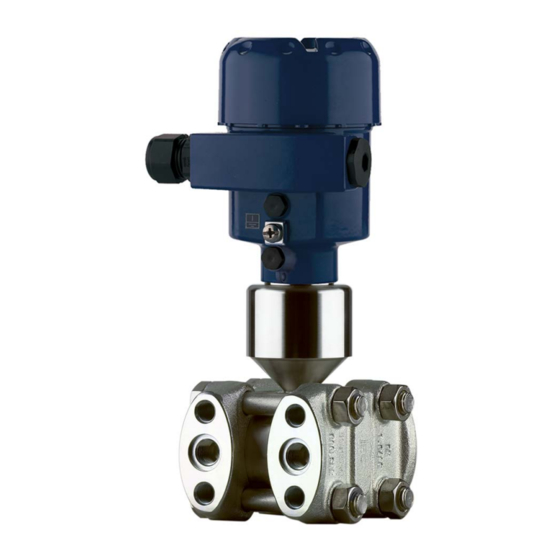
Page 7: Product Description
(optional) – Ex-specific "Safety instructions" (with Ex versions) – if necessary, further certificates Constituent parts The following illustration shows the components of DPT-10: + – Fig. 1: DPT-10 in basic version Housing cover, optionally with integrated display and adjustment module... -
Page 8: Principle Of Operation
Flow measurement – – Fig. 3: Flow measurement with DPT-10 and DP flow element, Q = flow, Δp = differential pressure, Δp = p Orifice Pitot tube WIKA Operating Instructions - Differential pressure transmitter DPT-10... - Page 9 Level measurement – – ρ g Fig. 4: Level measurement with DPT-10. Δp = differential pressure, ρ = density of the medium, g = acceleration of gravity Basic version with effective pressure lines Version with flange chemical seal Version with capillaries and cell chemical seals Differential pressure measurement Fig.
- Page 10 The configuration of the measuring cells differs depending on the measuring range: Fig. 8: Metallic measuring cell 10 mbar and 30 mbar - p and p process pres- sures Measuring element Silicone diaphragm Separating diaphragm Filling oil Integrated overvoltage arrester WIKA Operating Instructions - Differential pressure transmitter DPT-10...
-
Page 11: Adjustment
The instrument can be adjusted with the following adjustment media: • With the display and adjustment module • the suitable WIKA DTM in conjunction with an adjustment software according to the FDT/DTM standard, e.g. PACTware and PC • with manufacturer-specific adjustment programs AMS™ or PDM •... - Page 12 Protected against solar radiation • Avoiding mechanical shock and vibration • Storage and transport Storage and transport temperature see chapter "Supplement - temperature Technical data - Ambient conditions" • Relative humidity 20 … 85 % WIKA Operating Instructions - Differential pressure transmitter DPT-10...
-
Page 13: Mounting
When installing effective pressure lines outdoors, consider applying suitable anti-freeze protection, e.g. tube heating. Install effective pressure lines with a monotonic downward slope of at least 10 %. WIKA Operating Instructions - Differential pressure transmitter DPT-10... -
Page 14: Instructions For Oxygen Applications
Danger of explosion! Mounting and connection instructions Connection plus/minus When connecting the DPT-10 to the measurement loop, take note side of the plus/minus side of the process component. The plus side is marked with a "+", the minus side with a "-" on the process compo- nent next to the oval flanges. - Page 15 Thanks to the valve block it is possible to dismount the DPT-10 without interrupting the process. This means higher plant availability and simpler setup or maintenance. The 3-fold valve block with flanging on both sides enables a mechani- cally stable connection between the DPT-10 and e.g.
- Page 16 Process fitting Process fitting Inlet valve Inlet valve Breather valve 3-fold valve block, flang- The following illustration shows the connection of the 3-fold valve ing on both sides block, flanging on both sides. WIKA Operating Instructions - Differential pressure transmitter DPT-10...
- Page 17 Fig. 14: Connection of a 3-fold valve block, flanging on both sides Process fitting Process fitting Inlet valve Inlet valve Breather valve 5-fold valve block The following illustration shows the connection of the 5-fold valve block. WIKA Operating Instructions - Differential pressure transmitter DPT-10...
-
Page 18: Measurement Setup Flow
Valve for checking/ventilating Valve for checking/ventilating Inlet valve Inlet valve Breather valve Measurement setup flow → In gases Mount DPT-10 above the measurement loop so that condensate can drain off in the process cable. WIKA Operating Instructions - Differential pressure transmitter DPT-10... - Page 19 1. Mount DPT-10 below the measurement loop 2. Mount condensate vessels at the same height with the discharge socket and at the same distance to DPT-10 3. Fill the effective pressure lines to the height of the condensate vessels before setup...
- Page 20 When using a 5-fold valve block, the drain or blow-off valves are already integrated. In liquids 1. Mount DPT-10 below the measurement loop so that the effective pressure lines are always filled with liquid and gas bubbles can bubble up to the process line 2.
-
Page 21: Measurement Setup Level
Precipitator Drain valves 3-fold valve block Measurement setup level 1. Mount DPT-10 below the lower measurement connection so that In open vessels with ef- fective pressure line the effective pressure lines are always filled with liquid 2. Minus side is open to the atmospheric pressure 3. - Page 22 DPT-10 Minus side is open to the atmospheric pressure In closed vessels with ef- 1. Mount DPT-10 below the lower measurement connection so that fective pressure lines the effective pressure lines are always filled with liquid 2. Connect minus side always above the max. level 3.
- Page 23 Fig. 24: Measurement setup, level measurement in closed vessel DPT-10 In closed vessels with 1. Mount DPT-10 below the lower measurement connection so that steam layering with effec- the effective pressure lines are always filled with liquid tive pressure line 2.
- Page 24 4. For measurements in products with solid content such as e.g. dirty liquids, the installation of separators and drain valves is recommended to enable collection and removal of debris and sediment. WIKA Operating Instructions - Differential pressure transmitter DPT-10...
-
Page 25: Measurement Setup Density And Interface
The density measurement is carried out in the mode level measure- ment. 1. Mount DPT-10 below the lower chemical seal 2. The ambient temperature should be the same for both capillaries Example for a density measurement: Distance between the two measurement points: 0.3 m Min. - Page 26 = 1000 kg/m³ • 9.81 m/s • 0.3 m = 2943 Pa = 29.43 mbar 3. Mount DPT-10 below the lower chemical seal 4. The ambient temperature should be the same for both capillaries WIKA Operating Instructions - Differential pressure transmitter DPT-10...
-
Page 27: Measurement Setup Differential Pressure
Blocking valves Pipelines → In vapour and conden- Mount DPT-10 below the measurement loop so that some con- sate plants densate can collect in the effective pressure lines. The ventilation is carried out via the ventilation valves on the instru- ment, the 5-fold valve block enables blowing out the cables. - Page 28 5-fold valve block DPT-10 In liquids 1. Mount DPT-10 below the measurement loop so that the effective pressure lines are always filled with liquid and gas bubbles can bubble up to the process line 2. For measurements in products with solid content such as e.g.
-
Page 29: Mounting External Housing
1. Mount chemical seal with capillaries on top or laterally on the systems are used in all pipeline products 2. In vacuum applications: Mount DPT-10 below the measurement loop 3. The ambient temperature should be the same for both capillaries –... -
Page 30: Installation Control
The socket housing can be displaced by 180° to the wall mounting plate. Installation control Check the following after mounting the instrument: • Did you tighten all screws? • Closing screws and ventilation valves closed WIKA Operating Instructions - Differential pressure transmitter DPT-10... -
Page 31: Connecting To Power Supply
If screened cable is necessary, connect the cable screen on one or grounding both ends to ground potential depending on the plant installation. In the sensor, the screen must be connected directly to the internal WIKA Operating Instructions - Differential pressure transmitter DPT-10... -
Page 32: Connection Procedure
8. Press down the opening levers of the terminals, you will hear the terminal spring closing 9. Check the hold of the wires in the terminals by lightly pulling on them WIKA Operating Instructions - Differential pressure transmitter DPT-10... -
Page 33: Single Chamber Housing
12. Screw the housing cover back on The electrical connection is hence finished. Fig. 34: Connection steps 6 and 7 Single chamber housing The following illustrations apply to the non-Ex as well as to the Ex-ia version. WIKA Operating Instructions - Differential pressure transmitter DPT-10... -
Page 34: Double Chamber Housing
Fig. 36: Wiring plan, single chamber housing Voltage supply, signal output Double chamber housing The following illustration apply to non-Ex as well as Ex ia versions. The Exd version is described in the next subchapter. WIKA Operating Instructions - Differential pressure transmitter DPT-10... - Page 35 Terminals for the external display and adjustment unit Connection compartment I 2 C Fig. 38: Connection compartment, double chamber housing Spring-loaded terminals for voltage supply Plug connector for service interface Ground terminal for connection of the cable screen WIKA Operating Instructions - Differential pressure transmitter DPT-10...
- Page 36 Pin 1 Pin 2 Pin 3 Pin 4 Contact pin Colour connection ca- Terminal, electronics ble in the sensor module Pin 1 Brown Pin 2 White Pin 3 Blue Pin 4 Black WIKA Operating Instructions - Differential pressure transmitter DPT-10...
-
Page 37: Double Chamber Housing Ex D
Terminals for the external display and adjustment unit Connection compartment Fig. 42: Connection compartment, Ex-d double chamber housing Spring-loaded terminals for power supply and cable screen Ground terminal for connection of the cable screen WIKA Operating Instructions - Differential pressure transmitter DPT-10... -
Page 38: Version Ip 66/Ip 68, 1 Bar
Black Version IP 66/IP 68, 1 bar Wire assignment, con- nection cable Fig. 45: Wire assignment, connection cable brown (+) and blue (-) to power supply or to the processing system Shielding WIKA Operating Instructions - Differential pressure transmitter DPT-10... -
Page 39: Switch-On Phase
5 Connecting to power supply Switch-on phase Switch-on phase After connecting DPT-10 to power supply or after a voltage recur- rence, the instrument carries out a self-check for approx. 30 seconds: • Internal check of the electronics • Indication of the instrument type, the firmware as well as the sen- sor TAGs (sensor designation) •... -
Page 40: Adjustment With The Display And Adjustment Module
The display and adjustment module is used for measured value display, adjustment and diagnosis. It can be mounted in the following housing versions and instruments: • All sensors DPT-10 and IPT-1*, in the single as well as double chamber housing (optionally in the electronics or connection compartment) •... -
Page 41: Adjustment System
Adjustment system Fig. 47: Display and adjustment elements LC display Indication of the menu item number Adjustment keys WIKA Operating Instructions - Differential pressure transmitter DPT-10... -
Page 42: Set Parameters
[ESC] or the displayed limit value can be accepted with [OK]. Application The DPT-10 can be used for differential pressure, level, flow as well as density and interface measurement. The selection of the respective application is carried out in the menu item "Application". Dependent on the selected application, the adjustment is carried out as zero/ span or min./max. - Page 43 When switching over to adjustment in a height unit (for example for level measurement), the density also has to be entered. Proceed as follows to enter the density: 1. Push the [OK] button in the measured value display, the menu overview is displayed. WIKA Operating Instructions - Differential pressure transmitter DPT-10...
- Page 44 Position correction Offset 0.0000 bar 0.0035 bar 2. Select with [->], e.g. to accept the actual measured value 0.0035 bar. Position correction Accept current measured value? ▶ Accept Edit 3. Confirm with [OK]. WIKA Operating Instructions - Differential pressure transmitter DPT-10...
- Page 45 3. Confirm with [OK] and move to the menu overview with [ESC]. For an adjustment with pressure, simply enter the actual measured value indicated at the bottom of the display. The span adjustment is finished. WIKA Operating Instructions - Differential pressure transmitter DPT-10...
- Page 46 2. Set the requested value with [+] and [->], for example 100 %. 3. Confirm with [OK] and edit the requested bar value. 4. Set the requested bar value with [+] and [->], for example 29.4 mbar. WIKA Operating Instructions - Differential pressure transmitter DPT-10...
- Page 47 For an adjustment with flow, simply enter the actual measured value indicated at the bottom of the display. Information: The DPT-10 is also suitable for bidirectional flow measurement (flow in both directions). The selection is carried out in the menu item "Linearization curve". With the bidirectional flow measurement, the min.
- Page 48 Enter the requested parameters via the appropriate keys, save your settings and jump to the next menu item with the [->] key. Caution: Note the following if the DPT-10 with corresponding approval is used as part of an overfill protection system according to WHG (Water Resources Act): If a linearization curve is selected, the measuring signal is no longer necessarily linear to the filling height.
- Page 49 6 Adjustment with the display and adjustment module The DPT-10 has a root extraction function. It is selected in the menu item "Linearization curve". Linearization curve Linear Enter the requested parameters via the appropriate keys, save your settings and jump to the next menu item with the [->] key.
- Page 50 The following safety-relevant data are not uploaded or downloaded: • HART mode • Copy sensor data Copy sensor data? Reset Basic adjustment The reset "Basic adjustment" resets the values of the following menu items to the reset values (see chart): WIKA Operating Instructions - Differential pressure transmitter DPT-10...
- Page 51 Additional adjustment and diagnosis options such as e.g. scaling, simulation or trend curve presentation are shown in the following menu schematic. You will find a detailed description of these menu items in the operating instructions manual "Display and adjustment module". WIKA Operating Instructions - Differential pressure transmitter DPT-10...
-
Page 52: Menu Schematic
0.0000 bar Temperature unit ▼ 0.0000 bar 0.0000 bar °C Max. adjustment Damping Linearization curve Sensor-TAG ▶ Linear 100.00 % Horizontal cylindrical tank Sensor 0.5000 bar Spherical tank 0.0000 bar User programmable WIKA Operating Instructions - Differential pressure transmitter DPT-10... - Page 53 ▶ Display Diagnostics Service Info ▼ Displayed value Display unit Scaling Displayed value 0 % = 0.0 ▼ ▼ Scaled Differential pressure Volume ▼ 100 % = 100.0 Backlight ▼ Switched off WIKA Operating Instructions - Differential pressure transmitter DPT-10...
- Page 54 Copy sensor data? Enable? Address 0 Info Basic adjustment Display Diagnostics Service ▶ Info Instrument type Date of manufacture Last change using PC Sensor characteristics Display now? Serial number Software version 12345678 WIKA Operating Instructions - Differential pressure transmitter DPT-10...
-
Page 55: Saving The Parameter Adjustment Data
They are thus available for multiple use or service purposes. If DPT-10 is equipped with a display and adjustment module, the most important data can be read out of the sensor into the display and adjustment module. -
Page 56: Setup With The Adjustment Program Ams
Setup with the adjustment program AMS™ Parameter adjustment with AMS™ For WIKA sensors, instrument descriptions for the adjustment pro- gram AMS™ are available as DD. The instrument descriptions are already implemented in the current version of AMS™. For older ver- sions of AMS™, a free-of-charge download is available via Internet. -
Page 57: Setup
• Differential pressure measurement Flow measurement Instructions In flow measurement, DPT-10 is normally used without a chemical seal. Before adjusting DPT-10, you have to clean the effective pressure lines and the instrument must be filled with the medium. Measurement setup for gases –... - Page 58 3-fold valve block III Precipitator 1.5 Drain valves 2.4 Inlet valves Breather valve 6.7 Vent valves on DPT-10 A, B Blocking valves Prepare the adjustment Proceed as follows: 1. Close valve 3 WIKA Operating Instructions - Differential pressure transmitter DPT-10...
-
Page 59: Level Measurement
For level measurements, all versions of DPT-10 are employed. DPT-10 with double chemical seal is immediately ready for operation. The DPT-10 without chemical seal or with single chemical seal is ready for operation after opening a blocking valve, in case one is present. - Page 60 Briefly open valve 6, then close it: Fill the measuring instrument completely with the medium and remove air. 4. Set measurement loop to operation Now: Valve A open and valve 6 closed Then carry out adjustment, see below. WIKA Operating Instructions - Differential pressure transmitter DPT-10...
- Page 61 4. Set measurement loop to operation Now: Valve 3, 6 and 7 are closed Valves 2, 4, A and B are open Then carry out adjustment, see below. WIKA Operating Instructions - Differential pressure transmitter DPT-10...
- Page 62 4. Put measurement loop into operation: Close valve 3: Separate plus and minus side Open valve 4: Connect minus side Now: Valve 3, 6 and 7 are closed WIKA Operating Instructions - Differential pressure transmitter DPT-10...
-
Page 63: Density And Interface Measurement
For differential pressure measurements, DPT-10 without chemical seal or with double chemical seal is used. DPT-10 with double chemical seal is immediately ready for operation. Before adjusting DPT-10 without chemical seal, the effective pressure lines must be cleaned and the instrument filled with medium. - Page 64 4. Put measurement loop into operation: Close valve 3: Separate plus and minus side Open valve 4: Connect minus side Now: Arrangement with 5 valves. WIKA Operating Instructions - Differential pressure transmitter DPT-10...
- Page 65 Valves 1, 3, 5, 6 and 7 are closed Valves 2 and 4 are open Valves A and B open (if present) Then carry out adjustment, see chapter "Set parameters". Valves 1, 3, 5: Configuration with 5 valves. WIKA Operating Instructions - Differential pressure transmitter DPT-10...
-
Page 66: Maintenance And Fault Rectification
The operator of the system is responsible for taking suitable meas- tions occur ures to rectify faults. Failure reasons DPT-10 offers maximum reliability. Nevertheless, faults can occur dur- ing operation. These may be caused by the following, e.g.: • Sensor •... -
Page 67: Instrument Repair
Complete one form for each instrument • If necessary, state a contamination • Clean the instrument and pack it damage-proof • Attach the completed form and possibly also a safety data sheet to the instrument WIKA Operating Instructions - Differential pressure transmitter DPT-10... -
Page 68: Dismounting
Materials: see chapter "Technical data" If you have no way to dispose of the old instrument properly, please contact us concerning return and disposal. WIKA Operating Instructions - Differential pressure transmitter DPT-10... -
Page 69: Supplement
Max. torque screws mounting strap 30 Nm Max. torque screws socket external 5 Nm (3.688 lbf ft) housing Weight approx. 4.2 … 4.5 kg (9.26 … 9.92 lbs), depending on process fitting WIKA Operating Instructions - Differential pressure transmitter DPT-10... - Page 70 180 ms Chemical seal version, all nominal measuring ranges Dependent on the chemi- Dependent on the chemi- cal seal cal seal Damping (63 % of the input variable) 0 … 999 s, adjustable WIKA Operating Instructions - Differential pressure transmitter DPT-10...
- Page 71 Ʋ Relative humidity 45 … 75 % Ʋ Air pressure 860 … 1060 mbar/86 … 106 kPa (12.5 … 15.4 psig) Determination of characteristics Limit point adjustment according to IEC 61298-2 Characterstic curve Linear WIKA Operating Instructions - Differential pressure transmitter DPT-10...
- Page 72 4 … 20 mA. Specifications refer to the set span. Turn down (TD) is the ratio nominal measuring range/set span. Deviation - All versions The following applies to square root extracted characteristics: The accuracy data of DPT-10 are entered with factor 0.5 in the accuracy calculation of the flow. Deviation - Basic version 10 mbar, 30 mbar measuring cell Ʋ...
- Page 73 ±0.075 % of URL/70 bar pressure to the zero point Influence of the system ±0.14 % of URL/7 bar ±0.14 % of URL/70 bar ±0.14 % of URL/70 bar pressure to the span WIKA Operating Instructions - Differential pressure transmitter DPT-10...
- Page 74 10 mbar, 100 mbar ±0.18 % 500 mbar, 3 bar, 16 bar ±0.05 % ±0.125 % Ambient conditions Ambient, storage and transport temperature Ʋ Standard version -40 … +80 °C (-40 … +176 °F) WIKA Operating Instructions - Differential pressure transmitter DPT-10...
- Page 75 240 bar (24000 kPa) 500 mbar (50 kPa) 160 bar (16000 kPa) 160 bar (16000 kPa) 240 bar (24000 kPa) 420 bar (42000 kPa) 420 bar (42000 kPa) 630 bar (63000 kPa) WIKA Operating Instructions - Differential pressure transmitter DPT-10...
- Page 76 M20 x 1.5 – 1 x closing cap ½ NPT, 1 x blind plug ½ NPT – 1 x plug (depending on the version), 1 x blind stopper M20 x 1.5 WIKA Operating Instructions - Differential pressure transmitter DPT-10...
- Page 77 20 … 30 V DC Ʋ Ex d instrument 20 … 36 V DC Permissible residual ripple Ʋ < 100 Hz < 1 V Ʋ 100 Hz … 10 kHz < 10 mV Load see diagram WIKA Operating Instructions - Differential pressure transmitter DPT-10...
- Page 78 Protection class Approvals Depending on the version, instruments with approvals can have different technical data. For these instruments, please note the corresponding approval documents. They are included in the scope of delivery. WIKA Operating Instructions - Differential pressure transmitter DPT-10...
-
Page 79: Dimensions
½ NPT Fig. 60: Housing versions in protection IP 66/IP 68 (0.2 bar) - with integrated display and adjustment module the housing is 9 mm/0.35 in higher Single chamber version Double chamber version WIKA Operating Instructions - Differential pressure transmitter DPT-10... - Page 80 Fig. 62: Housing versions in protection IP 66/IP 68 (0.2 bar) - with integrated display and adjustment module the housing is 9 mm/0.35 in higher Single chamber version, electropolished Single chamber version, precision casting Double chamber version, precision casting WIKA Operating Instructions - Differential pressure transmitter DPT-10...
- Page 81 IEC 61518 ing screws RC 1/4 7/16-20 UNF AISI 316L incl. 2 vent valves (316L) 1/4-18 NPT PN 160: M10, PN Steel C 22.8 incl. 2 vent valves IEC 61518 420: M12 (316L) WIKA Operating Instructions - Differential pressure transmitter DPT-10...
- Page 82 (AISI 316L) and 2 ventilation valves 1/4-18 NPT 7/16-20 UNF Alloy C276 without valves/clos- IEC 61518 ing screws RC 1/4 7/16-20 UNF AISI 316L incl. 4 closing screws (AISI 316L) and 2 ventilation valves WIKA Operating Instructions - Differential pressure transmitter DPT-10...
- Page 83 98 mm 98 mm (3.94") (3.94") Fig. 65: left: Process fitting DPT-10 prepared for chemical seal assembly. right: Position of the copper ring seal Chemical seal connection Copper ring seal Cup diaphragm WIKA Operating Instructions - Differential pressure transmitter DPT-10...
- Page 84 – In liquids 20 WEEE directive 68 – In vapours 19 Wiring plan Functional principle 10 – Double chamber housing 36 – Single chamber housing 34 Interface measurement 26 Leak flow volume suppression 49 WIKA Operating Instructions - Differential pressure transmitter DPT-10...
- Page 85 Notes WIKA Operating Instructions - Differential pressure transmitter DPT-10...
- Page 86 Notes WIKA Operating Instructions - Differential pressure transmitter DPT-10...
- Page 87 Notes WIKA Operating Instructions - Differential pressure transmitter DPT-10...
- Page 88 All statements concerning scope of delivery, application, practi- cal use and operating conditions of the sensors and processing systems correspond to the information available at the time of printing. WIKA Alexander Wiegand SE & Co. KG Alexander-Wiegand-Straße 30 63911 Klingenberg Germany...
Need help?
Do you have a question about the DPT-10 and is the answer not in the manual?
Questions and answers