Table of Contents
Advertisement
Available languages
Available languages
Quick Links
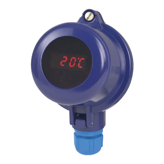
Connection head with integrated digital display
module (Ex i), model DIH10-Ex
Anschlusskopf mit integriertem digitalem
Anzeigemodul (Ex i), Typ DIH10-Ex
Tête de raccordement avec module d'affichage
numérique intégré (Ex i), type DIH10-Ex
Cabezal con indicador digital integrado (Ex i),
modelo DIH10-Ex
Operating instructions
Betriebsanleitung
Mode d'emploi
Manual de instrucciones
Model DIH10-Ex
EN
DE
FR
ES
Advertisement
Chapters
Table of Contents

Related Manuals for WIKA DIH10-Ex


Summary of Contents for WIKA DIH10-Ex
- Page 1 Connection head with integrated digital display module (Ex i), model DIH10-Ex Anschlusskopf mit integriertem digitalem Anzeigemodul (Ex i), Typ DIH10-Ex Tête de raccordement avec module d'affichage numérique intégré (Ex i), type DIH10-Ex Cabezal con indicador digital integrado (Ex i), modelo DIH10-Ex Model DIH10-Ex...
- Page 2 31 - 58 Mode d'emploi type DIH10-Ex Page 59 - 86 Manual de instrucciones modelo DIH10-Ex Página 87 - 114 © 02/2014 WIKA Alexander Wiegand SE & Co. KG All rights reserved. / Alle Rechte vorbehalten. WIKA is a registered trademark in various countries.
-
Page 3: Table Of Contents
6. Information on mounting and operation in hazardous areas 7. Faults 8. Maintenance and cleaning 9. Dismounting, return and disposal 10. Specifications Appendix: EU declaration of conformity Declarations of conformity can be found online at www.wika.com. WIKA operating instructions model DIH10-Ex... -
Page 4: General Information
Subject to technical modifications. ■ Further information: ■ - Internet address: www.wika.de / www.wika.com - Relevant data sheet: AC 80.11 - Application consultant: Tel.: +49 9372 132-0 Fax: +49 9372 132-406 info@wika.de WIKA operating instructions model DIH10-Ex... -
Page 5: Design And Function
2. Design and function 2. Design and function 2.1 Overview Model DIH10-Ex display module, operating side ▲ ▼ Connection head with integrated digital display Connection to thermometer (incl. protection cap) Connector pins for factory programming ... - Page 6 2. Design and function 2.2 Description The model DIH10-Ex display module is a universal, microprocessor- controlled display, monitoring and control instrument. It has an input, to which 4 … 20 mA standard signals can be connected. Thanks to simple installation and free programmability via the existing buttons, transmitters already in use can also be retrofitted in a short time.
- Page 7 Pipe support Stainless steel Pipe diameter R 1" ... 2" Cable gland 2 x M16 x 1.5 IP65 (option: IP67) Ingress protection 1) RAL 5022 2.4 Scope of delivery Cross-check scope of delivery with delivery note. WIKA operating instructions model DIH10-Ex...
-
Page 8: Safety
WARNING! ... indicates a potentially dangerous situation that can result in burns, caused by hot surfaces or liquids, if not avoided. Information ... points out useful tips, recommendations and information for efficient and trouble-free operation. WIKA operating instructions model DIH10-Ex... - Page 9 The cases are not constituent elements of the EC-type examination certificate. The DIH10-Ex is intrinsically safe and designed for use in hazardous areas. This is class A equipment for emissions and is intended for use in industrial environments.
- Page 10 ■ accordance with its intended use. that personal protective equipment is available. ■ WIKA operating instructions model DIH10-Ex...
- Page 11 The skilled personnel must have knowledge of ignition protection types, regulations and provisions for equipment in hazardous areas. Special operating conditions require further appropriate knowledge, e.g. of aggressive media. WIKA operating instructions model DIH10-Ex...
- Page 12 - Head/case labelling - Head/case product label Model Article number Approval-related data Year of manufacture Input / Current loop Temperature information WIKA operating instructions model DIH10-Ex...
- Page 13 ■ Model Input / Current loop Year of manufacture Manufacturer number Serial number Before mounting and commissioning the instrument, ensure you read the operating instructions! WIKA operating instructions model DIH10-Ex...
-
Page 14: Transport, Packaging And Storage
▶ When unloading packed goods upon delivery as well as during internal transport, proceed carefully and observe the symbols on the packaging. ▶ With internal transport, observe the instructions in chapter 4.2 “Packaging and storage”. WIKA operating instructions model DIH10-Ex... - Page 15 1. Wrap the instrument in an antistatic plastic film. 2. Place the instrument, along with the shock-absorbent material, in the packaging. 3. If stored for a prolonged period of time (more than 30 days), place a bag containing a desiccant inside the packaging. WIKA operating instructions model DIH10-Ex...
-
Page 16: Commissioning, Operation
Operation using a defective power supply unit (e.g. short circuit from the mains voltage to the output voltage) can result in life-threatening voltages at the instrument! 5.1 Operating a current loop Power internal supply bridge unit DC 24 V DIH10-Ex display Case WIKA operating instructions model DIH10-Ex... - Page 17 Terminal 2: Negative terminal of the current loop Terminals 3 and 4 are connected together on the PCB and enable the convenient connection of a transmitter built into the connection head. 4 ... 20 mA WIKA operating instructions model DIH10-Ex...
- Page 18 Ex ia IIC internal bridge 4 ... 20 mA 4 ... 20 mA Transmitter DIH10-Ex current loop current loop display Case * Power supply *) The cases are not constituent elements of the EC-type examination certificate. WIKA operating instructions model DIH10-Ex...
- Page 19 PN's will not be able to be saved. In order to reactivate the PIN code via PN50 on completion of any programming, the programming mode must be left (by the input of 0000 under PN50 or by briefly interrupting the current loop). WIKA operating instructions model DIH10-Ex...
- Page 20 1. Connect instrument in accordance with connection diagram. 2. Switch on the current-loop supply (current between 4 ... 20 mA). An initialisation and segment test is carried out. Then DIH10-Ex and subsequently the firmware version number (e.g. F1.24) is displayed.
-
Page 21: Information On Mounting And Operation In Hazardous Areas
Max. terminal voltage U = DC 30 V Max. current l 100 mA Max. power P The maximum effective capacitance and inductance are negligibly small. WIKA operating instructions model DIH10-Ex... - Page 22 The current loop display can be built into either a model BSZ-H ■ connection head or BSS-H connection head (with or without wall-mounting adapter). In this case, the case requirements referred to are fulfilled. The cases are not constituent elements of the EC-type examination certificate. WIKA operating instructions model DIH10-Ex...
-
Page 23: Faults
For these media, in addition to all standard regulations, the appropriate existing codes or regulations must also be followed. For contact details see chapter 1 “General information” or the back page of the operating instructions. WIKA operating instructions model DIH10-Ex... - Page 24 Sensor break or short circuit A horizontal bar I = 4 mA alternates with the 4 mA < I < 20 mA display “undr.” Sensor connected incorrectly but wrong value Wrong transmitter configuration WIKA operating instructions model DIH10-Ex...
-
Page 25: Maintenance And Cleaning
Do not use any aggressive cleaning agents. ▶ Do not use any hard or pointed objects for cleaning. 3. Wash or clean the dismounted instrument, in order to protect persons and the environment from exposure to residual media. WIKA operating instructions model DIH10-Ex... -
Page 26: Dismounting, Return And Disposal
9.2 Return Strictly observe the following when shipping the instrument: All instruments delivered to WIKA must be free from any kind of hazardous substances (acids, bases, solutions, etc.) and must therefore be cleaned before being returned. When returning the instrument, use the original packaging or a suitable transport packaging. -
Page 27: Specifications
LED, rotatable in 90° steps Measured value of display 7-segment, 8 mm high, red, 4-digit = display 9999 Overrange/Underrange to HI / to LO Display rate 0.1 s - 1 s - 10 s (adjustable) WIKA operating instructions model DIH10-Ex... - Page 28 Maximum terminal voltage U DC 30 V Maximum current l 100 mA Maximum power P Maximum capacitance C negligibly small Maximum inductance L negligibly small For further specifications see WIKA data sheet AC 80.11 and the order documentation. WIKA operating instructions model DIH10-Ex...
- Page 29 10. Specifications Dimensions in mm for the model DIH10-Ex display module 43 mm 40 mm WIKA operating instructions model DIH10-Ex...
-
Page 30: Appendix: Eu Declaration Of Conformity
Appendix: EU declaration of conformity WIKA operating instructions model DIH10-Ex... - Page 31 4. Transport, Verpackung und Lagerung 5. Inbetriebnahme, Betrieb 6. Hinweise zu Montage und Betrieb im explosionsgefährdeten Bereich 7. Störungen 8. Wartung und Reinigung 9. Demontage, Rücksendung und Entsorgung 10. Technische Daten Anlage: EU-Konformitätserklärung Konformitätserklärungen finden Sie online unter www.wika.de. WIKA Betriebsanleitung Typ DIH10-Ex...
-
Page 32: Allgemeines
Es gelten die allgemeinen Geschäftsbedingungen in den Verkaufsun- ■ terlagen. Technische Änderungen vorbehalten. ■ Weitere Informationen: ■ - Internet-Adresse: www.wika.de / www.wika.com - zugehöriges Datenblatt: AC 80.11 - Anwendungsberater: Tel.: +49 9372 132-0 Fax: +49 9372 132-406 info@wika.de WIKA Betriebsanleitung Typ DIH10-Ex... -
Page 33: Aufbau Und Funktion
2. Aufbau und Funktion 2. Aufbau und Funktion 2.1 Überblick Anzeigemodul Typ DIH10-Ex Bedienseite ▲ ▼ Anschlusskopf mit integrierter Digitalanzeige Anschluss zum Thermometer (inkl. Schutzkappe) Steckerkontakt für Werksprogrammierung Tasten für Programmierung ... - Page 34 2. Aufbau und Funktion 2.2 Beschreibung Das Anzeigemodul Typ DIH10-Ex ist ein universell einsetzbares, mikropro- zessorgesteuertes Anzeige-, Überwachungs- und Regelgerät. Es besitzt einen Eingang mit Anschlussmöglichkeit für Normsignale 4 … 20 mA. Durch einfache Montage und freie Programmierbarkeit über die vorhan- denen Tasten können auch bereits im Einsatz befindliche Messumformer...
- Page 35 Gewicht ca. 950 g Technische Daten Standardausführung Werkstoff Aluminium blau, lackiert Rohrhalterung CrNi-Stahl Rohrdurchmesser R 1" ... 2" Kabelverschraubung 2 x M16 x 1,5 IP65 (Option: IP67) Schutzart 1) RAL 5022 2.4 Lieferumfang Lieferumfang mit dem Lieferschein abgleichen. WIKA Betriebsanleitung Typ DIH10-Ex...
-
Page 36: Sicherheit
… weist auf eine möglicherweise gefährliche Situation hin, die durch heiße Oberflächen oder Flüssigkeiten zu Verbren- nungen führen kann, wenn sie nicht gemieden wird. Information … hebt nützliche Tipps und Empfehlungen sowie Informatio- nen für einen effizienten und störungsfreien Betrieb hervor. WIKA Betriebsanleitung Typ DIH10-Ex... - Page 37 Anschlussköpfe und kann so als Vor-Ort-Anzeige im gesam- ten industriellen Bereich eingesetzt werden. Die Gehäuse sind nicht Bestandteil der EG-Baumusterprüfbescheinigung. Der DIH10-Ex ist eigensicher für den Einsatz in explosionsgefährdeten Bereichen ausgeführt. Dies ist eine Einrichtung der Klasse A für Störaussendung und ist für den Betrieb in industrieller Umgebung vorgesehen.
- Page 38 Arbeitssicherheit, Erste Hilfe und Umweltschutz unterwiesen wird, sowie die Betriebsanleitung und insbesondere die darin enthaltenen Sicherheitshinweise kennt. dass das Gerät gemäß der bestimmungsgemäßen Verwendung für ■ den Anwendungsfall geeignet ist. dass die persönliche Schutzausrüstung verfügbar ist. ■ WIKA Betriebsanleitung Typ DIH10-Ex...
- Page 39 Richtlinien in der Lage, die beschriebenen Arbeiten auszuführen und mögliche Gefahren selbstständig zu erkennen. Das Fachpersonal muss Kenntnisse haben über Zündschutzarten, Vorschriften und Verordnungen für Betriebsmittel in explosionsgefährde- ten Bereichen. Spezielle Einsatzbedingungen verlangen weiteres entsprechendes Wissen, z. B. über aggressive Medien. WIKA Betriebsanleitung Typ DIH10-Ex...
- Page 40 Typenschilder bei Einbau im Anschlusskopf oder Gehäuse ■ - Beschriftung Kopf/Gehäuse - Typenschild Kopf/Gehäuse Artikelnummer Zulassungsrelevante Daten Herstellungsjahr Eingang / Stromschleife Temperaturangaben WIKA Betriebsanleitung Typ DIH10-Ex...
- Page 41 3. Sicherheit Typenschild Anzeigenmodul ■ Eingang / Stromschleife Herstellungsjahr Fabrikatsnummer Seriennummer Vor Montage und Inbetriebnahme des Gerätes unbedingt die Betriebsanleitung lesen! WIKA Betriebsanleitung Typ DIH10-Ex...
-
Page 42: Transport, Verpackung Und Lagerung
Bei unsachgemäßem Transport können Sachschäden in erheblicher Höhe entstehen. ▶ Beim Abladen der Packstücke bei Anlieferung sowie innerbetrieblichem Transport vorsichtig vorgehen und die Symbole auf der Verpackung beachten. ▶ Bei innerbetrieblichem Transport die Hinweise unter Kapitel 4.2 „Verpackung und Lagerung“ beachten. WIKA Betriebsanleitung Typ DIH10-Ex... - Page 43 Gerät wie folgt verpacken und lagern: 1. Das Gerät in eine antistatische Plastikfolie einhüllen. 2. Das Gerät mit dem Dämmmaterial in der Verpackung platzieren. 3. Bei längerer Einlagerung (mehr als 30 Tage) einen Beutel mit Trock- nungsmittel der Verpackung beilegen. WIKA Betriebsanleitung Typ DIH10-Ex...
-
Page 44: Inbetriebnahme, Betrieb
Einbau und Montage des Gerätes dürfen nur durch Fachpersonal erfolgen. ▶ Bei Betrieb mit einem defekten Netzgerät (z. B. Kurzschluss von Netzspannung zur Ausgangsspannung) können am Gerät lebensgefährliche Spannungen auftreten! 5.1 Betrieb einer Stromschleife Netzteil interne DC 24 V Brücke DIH10-Ex- Anzeige Gehäuse WIKA Betriebsanleitung Typ DIH10-Ex... - Page 45 Rückseite des Displays und ist nach Öffnen des Gehäuses zugänglich. Klemme 1: Pluspol der Stromschleife Klemme 2: Minuspol der Stromschleife Klemme 3 und Klemme 4 sind auf der Platine gebrückt und dienen zum komfortablen Anschluss eines im Anschlusskopf eingebauten Transmitters. 4 ... 20 mA WIKA Betriebsanleitung Typ DIH10-Ex...
- Page 46 Zusammenschaltung nach EN 60079-14 Nicht-Ex-Bereich Ex-Bereich Speisetrenner Ex ia IIC interne Brücke Mes- 4 ... 20 mA- 4 ... 20 mA DIH10-Ex- sumformer Stromschleife Stromschleife Anzeige Gehäuse * Hilfsenergie *) Die Gehäuse sind nicht Bestandteil der EG-Baumusterprüfbescheinigung. WIKA Betriebsanleitung Typ DIH10-Ex...
- Page 47 Änderungen unter den anderen PN nicht gespeichert werden können. Um nach einer Programmie- rung den PIN-Code unter PN50 wieder zu aktivieren, muss der Programmiermodus durch Eingabe von 0000 unter PN50 verlassen werden oder die Stromschleife kurzzeitig unterbrochen werden. WIKA Betriebsanleitung Typ DIH10-Ex...
- Page 48 2. Stromschleifenversorgung einschalten (Strom zwischen 4 ... 20 mA). Es erfolgt eine Initialisierung und ein Segmenttest. Dann wird DIH10-Ex und anschließend die Firmware-Versionsnummer angezeigt (z. B. F1.24). Danach schaltet die Anzeige in den Betriebsmodus. 3. Programmtaste P drücken, die Programmnummer P 0 wird angezeigt.
-
Page 49: Hinweise Zu Montage Und Betrieb Im Explosionsgefährdeten Bereich
EG-Baumusterprüfbescheinigung verwenden, mit denen die zulässi- gen elektrischen Grenzwerte des eigensicheren Stromkreises nicht überschritten werden: Max. Klemmenspannung U = DC 30 V Max. Strom l 100 mA Max. Leistung P Die maximale wirksame Kapazität und Induktivität sind vernachlässig- bar klein. WIKA Betriebsanleitung Typ DIH10-Ex... - Page 50 Warnhinweis besitzen. Die Stromschleifenanzeige ist optional in einem Anschlusskopf ■ Typ BSZ-H oder BSS-H (mit oder ohne Wandaufbauadapter) einge- baut. In diesem Fall sind die genannten Gehäuseanforderungen erfüllt. Die Gehäuse sind nicht Bestandteil der EG-Baumusterprüfbe- scheinigung. WIKA Betriebsanleitung Typ DIH10-Ex...
-
Page 51: Störungen
Am Gerät können im Fehlerfall aggressive Messstoffe mit extremer Temperatur und unter hohem Druck oder Vakuum anliegen. ▶ Bei diesen Messstoffen müssen über die gesamten allgemeinen Regeln hinaus die einschlägigen Vorschrif- ten beachtet werden. Kontaktdaten siehe Kapitel 1 „Allgemeines“ oder Rückseite der Betriebsanleitung. WIKA Betriebsanleitung Typ DIH10-Ex... - Page 52 I = > 20 mA Anzeige „over.“ Messbereiches Sensorbruch oder Sensorkurz- Wechselt ein I = 4 mA schluss Querbalken mit 4 mA < I < 20 mA der Anzeige Sensor falsch angeschlossen jedoch falscher „undr.“ Wert Falsche Transmitterkonfiguration WIKA Betriebsanleitung Typ DIH10-Ex...
-
Page 53: Wartung Und Reinigung
Eine unsachgemäße Reinigung führt zur Beschädigung des Gerätes! ▶ Keine aggressiven Reinigungsmittel verwenden. ▶ Keine harten und spitzen Gegenstände zur Reinigung verwenden. 3. Ausgebautes Gerät spülen bzw. säubern, um Personen und Umwelt vor Gefährdung durch anhaftende Messstoffreste zu schützen. WIKA Betriebsanleitung Typ DIH10-Ex... -
Page 54: Demontage, Rücksendung Und Entsorgung
Digitalanzeige nur im drucklosen Zustand demontieren. 9.2 Rücksendung Beim Versand des Gerätes unbedingt beachten: Alle an WIKA gelieferten Geräte müssen frei von Gefahrstoffen (Säuren, Laugen, Lösungen, etc.) sein und sind daher vor der Rücksendung zu reinigen. Zur Rücksendung des Gerätes die Originalverpackung oder eine geeig- nete Transportverpackung verwenden. -
Page 55: Technische Daten
7-Segment, 8 mm hoch, rot, 4 Digit = Anzeige 9999 Überlauf/Unterlauf nach HI / nach LO Anzeigezeit 0,1 s - 1 s - 10 s (einstellbar) Zulässige Temperaturen Arbeitstemperatur 0 ... 60 °C ■ Lagertemperatur -20 ... +80 °C ■ WIKA Betriebsanleitung Typ DIH10-Ex... - Page 56 Höchstwerten Höchstwerte Maximale Klemmenspannung U DC 30 V Maximaler Strom l 100 mA Maximale Leistung P Maximale Kapazität C vernachlässigbar klein Maximale Induktivität L vernachlässigbar klein Weitere technische Daten siehe WIKA-Datenblatt AC 80.11 und Bestell- unterlagen. WIKA Betriebsanleitung Typ DIH10-Ex...
- Page 57 10. Technische Daten Abmessungen in mm des Anzeigemoduls Typ DIH10-Ex 43 mm 40 mm WIKA Betriebsanleitung Typ DIH10-Ex...
-
Page 58: Anlage: Eu-Konformitätserklärung
Anlage: EU-Konformitätserklärung WIKA Betriebsanleitung Typ DIH10-Ex... - Page 59 6. Informations concernant le montage et l'utilisation dans des zones explosives 7. Dysfonctionnements 8. Entretien et nettoyage 9. Démontage, retour et mise au rebut 10. Spécifications Annexe : Déclaration de conformité UE Déclarations de conformité disponibles sur www.wika.fr. WIKA mode d'emploi type DIH10-Ex...
-
Page 60: Généralités
- Consulter notre site Internet : www.wika.fr - Fiche technique correspondante : AC 80.11 - Conseiller applications : Tel. : 0 820 951010 (0,15 €/min) +33 1 787049-46 Fax : 0 891 035891 (0,35 €/min) info@wika.fr WIKA mode d'emploi type DIH10-Ex... -
Page 61: Conception Et Fonction 61 Fr
2. Conception et fonction 2. Conception et fonction 2.1 Vue générale Module d'affichage type DIH10-Ex, côté de service ▲ ▼ Tête de raccordement avec affichage numérique intégré Connexion vers le thermomètre (y compris bouchon de protection) ... - Page 62 2. Conception et fonction 2.2 Description Le type DIH10-Ex est un affichage universel contrôlé par un microprocesseur et un instrument de surveillance et de contrôle. Il a une entrée à laquelle des signaux standard 4 ... 20 mA peuvent être connectés.
- Page 63 Diamètre de tuyauterie R 1" ... 2" Presse-étoupe 2 x M16 x 1,5 IP65 (option: IP67) Indice de protection 1) RAL 5022 2.4 Détail de la livraison Comparer le détail de la livraison avec le bordereau de livraison. WIKA mode d'emploi type DIH10-Ex...
-
Page 64: Sécurité
à des surfaces ou liquides chauds si elle n'est pas évitée. Information ... met en exergue les conseils et recommandations utiles de même que les informations permettant d'assurer un fonctionnement efficace et normal. WIKA mode d'emploi type DIH10-Ex... - Page 65 Les boîtiers ne sont pas des éléments constitutifs du certificat d'examen de type CE. Le DIH10-Ex est à sécurité intrinsèque et a été conçu pour une utilisation en zone explosive. Ceci est un matériel classé A pour les émissions, et est prévu pour une utilisation dans des environnements industriels.
- Page 66 à intervalles réguliers sur tous ■ les sujets concernant la sécurité du travail, les premiers secours et la protection de l'environnement et qu'il connaît le mode d'emploi et particulièrement les consignes de sécurité contenues dans celui-ci. WIKA mode d'emploi type DIH10-Ex...
- Page 67 Le personnel qualifié doit avoir les connaissances requises des types de protection contre l'ignition, des règlementations et dispositions concernant les équipements en zones explosives. Les conditions d'utilisation spéciales exigent également une connaissance adéquate, par ex. des liquides agressifs. WIKA mode d'emploi type DIH10-Ex...
- Page 68 - Plaque signalétique tête/boîtier Type Numéro d'article Données d’agrément liées Année de fabrication Entrée / boucle de courant Informations concernant la température WIKA mode d'emploi type DIH10-Ex...
- Page 69 Entrée / boucle de courant Année de fabrication Numéro du fabricant Numéro de série Lire impérativement le mode d'emploi avant le montage et la mise en service de l'instrument ! WIKA mode d'emploi type DIH10-Ex...
-
Page 70: Transport, Emballage Et Stockage
▶ Lors du transport en interne, observer les instructions du chapitre 4.2 “Emballage et stockage”. WIKA mode d'emploi type DIH10-Ex... - Page 71 1. Emballer l'instrument dans une feuille de plastique antistatique. 2. Placer l'instrument avec le matériau isolant dans l'emballage. 3. En cas de stockage prolongé (plus de 30 jours), mettre également un sachet absorbeur d'humidité dans l'emballage. WIKA mode d'emploi type DIH10-Ex...
-
Page 72: Mise En Service, Utilisation
(par exemple court-circuit entre la tension du secteur et la tension de sortie), des tensions présentant un danger de mort peuvent apparaître sur l'instrument ! 5.1 Fonctionnement d'une boucle de courant Unité pont d'alimen- interne tation 24 VDC Affichage DIH10-Ex Boîtier WIKA mode d'emploi type DIH10-Ex... - Page 73 Borne 2 : borne négative de la boucle de courant Les bornes 3 et 4 sont raccordées ensemble sur le PCB et permettent une connexion facile d'un transmetteur placé dans la tête de raccordement. 4 ... 20 mA WIKA mode d'emploi type DIH10-Ex...
- Page 74 4 ... 20 mA 4 ... 20 mA Transmetteur Affichage boucle de courant boucle de courant DIH10-Ex Boîtier * Alimentation *) Les boîtiers ne sont pas des éléments constitutifs du certificat d'examen de type CE. WIKA mode d'emploi type DIH10-Ex...
- Page 75 PN ne pourra pas être sauvegardée. Pour réactiver le code PIN via PN50 en achevant toute programmation, le mode de programmation doit être quitté (en entrant 0000 sous PN50 ou en interrompant brièvement la boucle de courant). WIKA mode d'emploi type DIH10-Ex...
- Page 76 1. Connecter l'instrument en respectant le diagramme de connexion. 2. Allumer l'alimentation de boucle de courant (courant entre 4 ... 20 mA). Un test d'initialisation et de segment est effectué. Alors DIH10-Ex et ensuite le numéro de version du micrologiciel (par exemple F1.24) s'affiche.
-
Page 77: Informations Concernant Le Montage Et L'utilisation Dans Des Zones Explosives
électriques admissibles du circuit intrinsèquement sûr ne seront pas dépassées : Tension aux bornes maximale U = 30 VDC Courant maximum l 100 mA Puissance maximale P La capacité et la conductivité internes effectives maximales sont négligeables. WIKA mode d'emploi type DIH10-Ex... - Page 78 BSZ-H soit dans une tête de raccordement BSS-H (avec ou sans adaptateur de montage sur paroi). Dans ce cas, les exigences de boîtier mentionnées sont remplies. Les boîtiers ne sont pas des éléments constitutifs du certificat d'examen de type CE. WIKA mode d'emploi type DIH10-Ex...
-
Page 79: Dysfonctionnements
Pour ces fluides, les codes et directives appropriés existants doivent être observés en plus des régulations standard. Pour le détail des contacts, merci de consulter le chapitre 1 “Généralités” ou le dos du mode d'emploi. WIKA mode d'emploi type DIH10-Ex... - Page 80 Une barre horizontale I = 4 mA Rupture de capteur ou court- alterne avec circuit 4 mA < I < 20 mA l'affichage “undr.” mais valeur fausse Capteur mal raccordé Configuration du transmetteur non adapté WIKA mode d'emploi type DIH10-Ex...
-
Page 81: Entretien Et Nettoyage
Ne pas utiliser de détergents agressifs. ▶ Ne pas utiliser d'objets pointus ou durs pour le nettoyage. 3. Laver et décontaminer l'instrument démonté afin de protéger les personnes et l'environnement contre le danger lié aux résidus de fluides. WIKA mode d'emploi type DIH10-Ex... -
Page 82: Démontage, Retour Et Mise Au Rebut
été mis hors pression. 9.2 Retour En cas d'envoi de l'instrument, il faut respecter impérativement ceci : Tous les instruments livrés à WIKA doivent être exempts de substances dangereuses (acides, bases, solutions, etc.) et doivent donc être nettoyés avant d'être retournés. -
Page 83: Spécifications
Principe d'affichage Valeur mesurée de l'affichage 7 segments, 8 mm de hauteur, rouge, 4 digits = affichage 9999 Dépassement inférieur/Supérieur vers HI / vers LO Vitesse d'affichage 0,1 s - 1 s - 10 s (réglable) WIKA mode d'emploi type DIH10-Ex... - Page 84 30 VDC Courant maximal l 100 mA Puissance maximale P Capacité maximale C négligeable Conductivité maximale L négligeable Pour de plus amples spécifications, voir la fiche technique WIKA AC 80.11 et la documentation de commande. WIKA mode d'emploi type DIH10-Ex...
- Page 85 10. Spécifications Dimensions en mm pour le module d'affichage type DIH10-Ex 43 mm 40 mm WIKA mode d'emploi type DIH10-Ex...
-
Page 86: Annexe : Déclaration De Conformité Ue
Annexe : Déclaration de conformité UE WIKA mode d'emploi type DIH10-Ex... - Page 87 6. Notas acerca del montaje y servicio en zonas potencialmente explosivas 7. Errores 8. Mantenimiento y limpieza 9. Desmontaje, devolución y eliminación de residuos 10. Datos técnicos Anexo: Declaración de conformidad UE Declaraciones de conformidad puede encontrar en www.wika.es. WIKA manual de instrucciones modelo DIH10-Ex...
-
Page 88: Información General
Modificaciones técnicas reservadas. ■ Para obtener más informaciones consultar: ■ - Página web: www.wika.es - Hoja técnica correspondiente: AC 80.11 - Servicio técnico: Tel.: +34 933 938 630 Fax: +34 933 938 666 info@wika.es WIKA manual de instrucciones modelo DIH10-Ex... -
Page 89: Diseño Y Función
2. Diseño y función 2. Diseño y función 2.1 Resumen Módulo de indicación DIH10-Ex (lado de mando) ▲ ▼ Cabezal con indicador digital integrado Conexión al termómetro (incl. tapa protectora) Pines de conexión para la programación de fábrica ... - Page 90 2. Diseño y función 2.2 Descripción El módulo de indicación modelo DIH10-Ex es un instrumento de indicación, supervisión y regulación de uso universal, controlado por microprocesador. Dispone de una entrada con conector para señales estándar de 4 ... 20 mA.
- Page 91 Diámetro del tubo R 1" ... 2" Prensaestopa 2 x M16 x 1,5 IP65 (opción: IP67) Tipo de protección 1) RAL 5022 2.4 Volumen de suministro Comparar mediante el albarán si se han entregado todas las piezas. WIKA manual de instrucciones modelo DIH10-Ex...
-
Page 92: Seguridad Es
... indica una situación probablemente peligrosa que pueda causar quemaduras debido a superficies o líquidos calientes si no se evita. Información ... marca consejos y recomendaciones útiles así como informaciones para una utilización eficaz y libre de fallos. WIKA manual de instrucciones modelo DIH10-Ex... - Page 93 Un manejo no apropiado o una utilización del instrumento no conforme a las especificaciones técnicas requiere la inmediata puesta fuera de servicio y la comprobación por parte de un técnico autorizado por WIKA. No se admite ninguna reclamación debido a una utilización no conforme a lo previsto.
- Page 94 ■ aplicación. el equipo de protección individual esté disponible. ■ WIKA manual de instrucciones modelo DIH10-Ex...
- Page 95 El personal técnico debe tener conocimientos sobre los tipos de protección contra incendios, los reglamentos y las directivas referentes a equipos en zonas potencialmente explosivas. Algunas condiciones de uso específicas requieren conocimientos adicionales, p. ej. acerca de medios agresivos. WIKA manual de instrucciones modelo DIH10-Ex...
- Page 96 - Placa de identificación cabezal/caja Modelo Código Datos relevantes de la homologación Año de fabricación Entrada / Bucle de corriente Datos de temperatura WIKA manual de instrucciones modelo DIH10-Ex...
- Page 97 Entrada / Bucle de corriente Año de fabricación Número de fabricación Número de serie ¡Es absolutamente necesario leer el manual de instrucciones antes del montaje y la puesta en servicio del instrumento! WIKA manual de instrucciones modelo DIH10-Ex...
-
Page 98: Transporte, Embalaje Y Almacenamiento
Tener cuidado al descargar los paquetes durante la entrega o el transporte dentro de la compañía y respetar los símbolos en el embalaje. ▶ Observar las instrucciones en el capítulo 4.2 “Embalaje y almacenamiento” en el transporte dentro de la compañía. WIKA manual de instrucciones modelo DIH10-Ex... - Page 99 1. Envolver el instrumento en un film de plástico antiestático. 2. Colocar el instrumento junto con el material aislante en el embalaje. 3. Para un almacenamiento prolongado (más de 30 días) colocar una bolsa con un desecante en el embalaje. WIKA manual de instrucciones modelo DIH10-Ex...
-
Page 100: Puesta En Servicio, Funcionamiento
(p. ej., cortocircuito de la tensión de red a la tensión de salida), pueden generarse tensiones letales en el instrumento! 5.1 Operación de un bucle de corriente Fuente Puente interno alimenta- ción DC 24 V Indicador DIH10-Ex Caja WIKA manual de instrucciones modelo DIH10-Ex... - Page 101 Borne 2: polo negativo del bucle de corriente Los bornes 3 y 4 están puenteados en la placa, y sirven para la conexión cómoda de un transmisor montado en el cabezal. 4 ... 20 mA WIKA manual de instrucciones modelo DIH10-Ex...
- Page 102 4 ... 20 mA Bucle de corriente Transmisor Indicador Bucle de corriente de 4 ... 20 mA DIH10-Ex Caja *) Alimentación auxiliar *) Las cajas no están incluidas en el certificado de tipo CE. WIKA manual de instrucciones modelo DIH10-Ex...
- Page 103 PN50, de lo contrario las modificaciones realizadas en los demás PN no pueden ser guardadas. Para activar nuevamente el código PIN en PN50 tras una programación, hay que salir del modo de programación introduciendo 0000 en PN50, o interrumpir brevemente el bucle de corriente. WIKA manual de instrucciones modelo DIH10-Ex...
- Page 104 2. Encender el suministro de bucle de corriente (corriente entre 4 ... 20 mA). Se realiza una inicialización y una prueba de segmento. Entonces se visualiza DIH10-Ex y a continuación el número de versión de firmware (por ejemplo F1.24). Después de eso, el indicador cambia al modo de funcionamiento.
-
Page 105: Notas Acerca Del Montaje Y Servicio En Zonas Potencialmente Explosivas
Tensión máxima de bornes U = DC 30 V Corriente máx. l 100 mA Potencia máx. P La capacidad máxima efectiva y la inductancia son insignificantemente pequeñas. WIKA manual de instrucciones modelo DIH10-Ex... - Page 106 BSZ-H o BSS-H (con o sin adaptador de montaje en pared). En este caso, se cumple con los mencionados requerimientos de la caja. Las cajas no están incluidas en el certificado de tipo CE. WIKA manual de instrucciones modelo DIH10-Ex...
-
Page 107: Errores
▶ Con estos medios deben observarse en cada caso, además de todas las reglas generales, las disposiciones pertinentes. Datos de contacto véase el capítulo 1 “Información general” o parte posterior del manual de instrucciones. WIKA manual de instrucciones modelo DIH10-Ex... - Page 108 Sensor roto o cortocircuito en Cambia una barra I = 4 mA el sensor transversal con la 4 mA < I < 20 mA indicación “undr”. Conexión incorrecta del sensor sin embargo, valor incorrecto Configuración incorrecta del transmisor WIKA manual de instrucciones modelo DIH10-Ex...
-
Page 109: Mantenimiento Y Limpieza
No utilizar productos de limpieza agresivos. ▶ No utilizar ningún objeto puntiagudo o duro para la limpieza. 3. Enjuagar y limpiar el dispositivo desmontado para proteger a las personas y el medio ambiente contra peligros por medios residuales adherentes. WIKA manual de instrucciones modelo DIH10-Ex... -
Page 110: Desmontaje, Devolución Y Eliminación De Residuos
9.2 Devolución Es imprescindible observar lo siguiente para el envío del instrumento: Todos los instrumentos enviados a WIKA deben estar libres de sustancias peligrosas (ácidos, lejías, soluciones, etc.) y, por lo tanto, deben limpiarse antes de devolver. Utilizar el embalaje original o un embalaje adecuado para la devolución del instrumento. -
Page 111: Datos Técnicos
LED, girable en 90 pasos Lectura del indicador 7 segmentos, altura 8 mm, rojo, 4 dígitos = indicación 9999 Desbordamiento/ hacia HI/hacia LO subdesbordamiento Tiempo de indicación 0,1 s - 1 s - 10 s (ajustable) WIKA manual de instrucciones modelo DIH10-Ex... - Page 112 Corriente máxima l Potencia máxima P Capacidad máxima C De dimensión despreciable Inductividad máxima L De dimensión despreciable Para más datos técnicos véase hoja técnica de WIKA AC 80.11 y la documentación de pedido. WIKA manual de instrucciones modelo DIH10-Ex...
- Page 113 10. Datos técnicos Dimensiones en mm del módulo de indicación modelo DIH10-Ex 43 mm 40 mm WIKA manual de instrucciones modelo DIH10-Ex...
-
Page 114: Anexo: Declaración De Conformidad Ue
Anexo: Declaración de conformidad UE WIKA manual de instrucciones modelo DIH10-Ex... - Page 115 WIKA operating instructions model DIH10-Ex...
- Page 116 WIKA subsidiaries worldwide can be found online at www.wika.com. WIKA-Niederlassungen weltweit finden Sie online unter www.wika.de. La liste des filiales WIKA dans le monde se trouve sur www.wika.fr Sucursales WIKA en todo el mundo puede encontrar en www.wika.es. WIKA Alexander Wiegand SE & Co. KG Alexander-Wiegand-Strasse 30 63911 Klingenberg •...
Need help?
Do you have a question about the DIH10-Ex and is the answer not in the manual?
Questions and answers