
Related Manuals for WIKA DI32-1


Summary of Contents for WIKA DI32-1
- Page 1 Operating instructions Betriebsanleitung Digital indicator, model DI32-1 Digitalanzeige, Typ DI32-1 Digital indicator, model DI32-1...
- Page 2 3 - 68 Betriebsanleitung Typ DI32-1 Seite 69 - 134 Further languages can be found on www.wika.com © 2015 WIKA Alexander Wiegand SE & Co. KG All rights reserved. / Alle Rechte vorbehalten. WIKA is a registered trademark in various countries. ®...
- Page 3 7.9 Menu tree ..........27 WIKA operating instructions digital indicator, model DI32-1...
- Page 4 12.4 Assigning key functions ........50 WIKA operating instructions digital indicator, model DI32-1...
- Page 5 19. Specifications ..........66 Declarations of conformity can be found online at www.wika.com...
- Page 6 Subject to technical modifications. ■ Further information: ■ - Internet address: www.wika.de / www.wika.com - Relevant data sheet: AC 80.13 - Application consultant: Tel.: +49 9372 132-0 Fax: +49 9372 132-406 info@wika.de WIKA operating instructions digital indicator, model DI32-1...
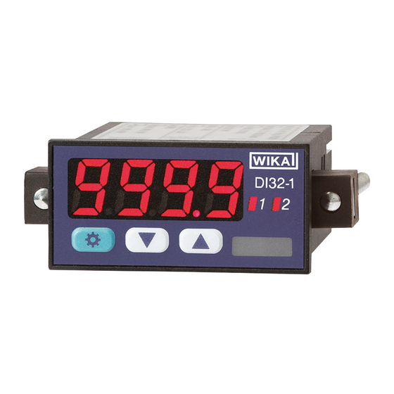
- Page 7 Displays the status of the switching outputs Mounting element with clamping Used for fixing screws 7-segment display Displays measured values, program numbers or parameters Product label Contains product information WIKA operating instructions digital indicator, model DI32-1...
- Page 8 2. Design and function 2.2 Description The DI32-1 is a 4-digit digital indicator for the measurement of different measure- ment signals (voltage, current, temperature and frequency). The configuration is made via three front keys. Password protection prevents unwanted changes to the parameters.
- Page 9 3.2 Intended use The DI32-1 digital indicator is designed for the evaluation and display of sensor signals. With the switching outputs, it is possible to realise simple control functions. The digital indicator is not permitted to be used in hazardous areas.
- Page 10 The skilled electrical personnel have been specifically trained for the work environment they are working in and know the relevant stand- ards and regulations. The skilled electrical personnel must comply with current legal accident prevention regulations. WIKA operating instructions digital indicator, model DI32-1...
- Page 11 Outputs supply 9 8 7 6 5 4 3 2 1 Serial number Model Pin assignment Symbols Before mounting and commissioning the instrument, ensure you read the operating instructions! WIKA operating instructions digital indicator, model DI32-1...
- Page 12 If the original packaging is not available, pack and store the instrument as described below: 1. Wrap the instrument in a plastic film. 2. Place the instrument, along with the shock-absorbent material, in the packaging. WIKA operating instructions digital indicator, model DI32-1...
- Page 13 5.2 Mounting Mounting element Clamping screw Sealing Cutting out the control panel Control panel thickness max. 3 mm ■ Panel cutout 45.0 x 22.2 +0.6 +0.3 ■ WIKA operating instructions digital indicator, model DI32-1...
- Page 14 Connect the power supply. ▶ » Segment test is carried out. Check the correct operation of all LEDs » Software type and software version are displayed. » Digital indicator is ready for operation. WIKA operating instructions digital indicator, model DI32-1...
- Page 15 Switching points 1/2 V 10 V 50 mV Transmitter Switching points GND S2 supply GND S2 WIKA operating instructions digital indicator, model DI32-1 0-1/2...10 V, 9-28 VDC 0-1/2...10 V 9-28 VDC 1/2 V 50 mV 10 V 50 mV Transmitter...
- Page 16 9-28 VDC 9-28 VDC 9-28 VDC Encoder Supply Encoder Supply Encoder Supply Encoder Supply Sensor Sensor supply supply WIKA operating instructions digital indicator, model DI32-1 Switching points Switching points Switching points Switching points 0-1/2...10 V, 9-28 VDC GND S2 GND S2...
- Page 17 9-28 VDC Supply Supply Supply Supply Encoder Encoder Encoder Encoder Sensor Sensor supply supply 9-28 VDC 9-28 VDC 9-28 VDC 9-28 VDC Supply Supply Supply Supply Encoder Encoder Encoder Encoder Sensor Sensor supply supply WIKA operating instructions digital indicator, model DI32-1...
- Page 18 GND S2 GND S2 GND S2 GND S2 GND S2 Reset Reset Reset Reset 9-28 VDC 9-28 VDC Reset Reset Reset Reset Reset Reset Reset Reset 9-28 VDC 9-28 VDC 9-28 VDC 9-28 VDC WIKA operating instructions digital indicator, model DI32-1...
- Page 19 NPN output, low side Relay Relay Relay 9-28 VDC 9-28 VDC 9-28 VDC PNP output, high side 9-28 VDC 9-28 VDC 9-28 VDC Push-pull output, low side and high side 9-28 VDC 9-28 VDC 9-28 VDC WIKA operating instructions digital indicator, model DI32-1...
- Page 20 [☼] -1999 … 9999 ge * [▲] [▼] dot.A 0000 … 0.000 [☼] [▲] [▼] uring range EndA [☼] -19.99 … 99.99 [▲] [▼] uring range OFFA [☼] -19.99 … 99.99 WIKA operating instructions digital indicator, model DI32-1 [▲] [▼]...
- Page 21 6.4 Accessing and exiting programming mode Accessing Press [☼]. ▶ » “TYPE” will be shown in the display. Exit The digital indicator reverts to operating mode automatically after 10 seconds of inactivity. The entered settings will be saved. WIKA operating instructions digital indicator, model DI32-1...
- Page 22 DC 0 ... 2 V 0 - 1 DC 0 ... 1 V 0 - 50 DC 0 ... 50 mV 0 - 20 0 ... 20 mA 4 - 20 4 ... 20 mA WIKA operating instructions digital indicator, model DI32-1...
- Page 23 Specifies the number of decimal places that are displayed on the screen. This parameter has no influence on the scaling or the indication value. [☼] TYPE [▲] [▼] dot.A [☼] 0000 [▲] [▼] 000.0 00.00 0.000 WIKA operating instructions digital indicator, model DI32-1...
- Page 24 A defined indication range is represented by 0000. With this function a fluctuating indication of the zero point is avoided. Example: Parameter 10 = indication range -10 ... +10 is displayed as 0000. [☼] TYPE [▲] [▼] 00 … 99 ZErO [☼] WIKA operating instructions digital indicator, model DI32-1...
- Page 25 The input signal is monitored to ±5 % of the measuring range. The indication range is also monitored. 10Pr The input signal is monitored to ±10 % of the measuring range. The indication range is also monitored. WIKA operating instructions digital indicator, model DI32-1...
- Page 26 [☼] TYPE [▲] [▼] SPC.A [☼] 0 … 5 [▲] [▼] dIS.1 [☼] -1999 … 9999 [▲] [▼] InP.1 [☼] -1999 … 9999 [☼] -1999 … 9999 dIS.5 InP.5 [☼] -1999 … 9999 WIKA operating instructions digital indicator, model DI32-1...
- Page 27 Zero point suppression ZErO [☼] 00 … 99 [▲] [▼] Overrun and underrun OUEr [☼] [▲] behaviour [▼] rAnG [▲] [▼] 10Pr Number of SPC.A 0 … 5 [☼] WIKA operating instructions digital indicator, model DI32-1 programmable points [▲] [▼]...
- Page 28 -1999 … 9999 [☼] Programmable point 1 [▲] [▼] Indications value dIS.5 -1999 … 999 [☼] Programmable point 5 [▲] [▼] Analogue value InP.5 [☼] -1999 … 9999 Programmable point 5 General settings WIKA operating instructions digital indicator, model DI32-1...
- Page 29 Pt1000 2-wire -200 ... +850 °C tYP.N Thermocouple type N tYP.L Thermocouple type L tYP.E Thermocouple type E tYP.J Thermocouple type J tYP.T Thermocouple type T tYP.K Thermocouple type K tYP.R Thermocouple type R WIKA operating instructions digital indicator, model DI32-1...
- Page 30 Measurement in °F: -36 ... +36 ■ If the unit is changed under “Unlt”, the value under “OFFS” will be converted and rounded. [☼] TYPE [▲] [▼] -19,9 … 19,9 °C OFFS [☼] -35,9 … 35,9 °F WIKA operating instructions digital indicator, model DI32-1...
- Page 31 Unit * UnIt [☼] °C [▲] [▼] °F [▲] [▼] OFFS [☼] -19.9 … 19.9 ( °C) Wire matching [▲] [▼] -35.9 … 35.9 (°F) General settings WIKA operating instructions digital indicator, model DI32-1...
- Page 32 9.2 Selecting triggering of the pulse input [☼] TYPE [▲] [▼] I.tYP [☼] [▲] [▼] Parameter Description Active TTL signals 0.8 ... 2 V Passive switch contact. Internal pull-up is switched. Active sensor output. Internal pull-down is switched. WIKA operating instructions digital indicator, model DI32-1...
- Page 33 50 Hz with a pulse-duty factor of 1:1 (minimum pulse length 10 ms) 100 Hz with a pulse-duty factor of 1:1 (minimum pulse length 5 ms) 500 Hz with a pulse-duty factor of 1:1 (minimum pulse length 1 ms) WIKA operating instructions digital indicator, model DI32-1...
- Page 34 Specifies the number of decimal places that are displayed on the screen. This parameter has no influence on the scaling or the indication value. [☼] TYPE [▲] [▼] [☼] 0000 dot.F [▲] [▼] 000.0 00.00 0.000 WIKA operating instructions digital indicator, model DI32-1...
- Page 35 00.00 ... 99.99 9.8 Setting the offset adjustment (TARE) The characteristic curve of the input signal is shifted in parallel by the offset value. [☼] TYPE [▲] [▼] -1999 … 9999 tArA [☼] WIKA operating instructions digital indicator, model DI32-1...
- Page 36 [☼] TYPE [▲] [▼] SPC.F [☼] 0 … 5 [▲] [▼] dIS.1 -1999 … 9999 [☼] [▲] [▼] InP.1 -1999 … 9999 [☼] [☼] -1999 … 9999 dIS.5 InP.5 [☼] -1999 … 9999 WIKA operating instructions digital indicator, model DI32-1...
- Page 37 FILt [☼] [▲] [▼] [▲] [▼] End of measuring range [☼] -1999 … 9999 Indication range * [▲] [▼] Start of measuring range OFFS -1999 … 9999 [☼] Indication range * WIKA operating instructions digital indicator, model DI32-1 [▲] [▼]...
- Page 38 InP.1 [☼] -1999 … 9999 Programmable point1 [▲] [▼] Indication value dIS.5 [☼] -1999 … 999 Programmable point 5 [▲] [▼] Analogue value InP.5 [☼] -1999 … 9999 Programmable point 5 General settings WIKA operating instructions digital indicator, model DI32-1...
- Page 39 I.tYP [☼] [▲] [▼] Parameter Description Active TTL signals 0.8 ... 2 V Passive switch contact, which switches the internal pull-up to ground. Active sensor output. In the indicator a pull-down is switched WIKA operating instructions digital indicator, model DI32-1...
- Page 40 100 Hz with a pulse-duty factor of 1:1 (minimum pulse length 5 ms) 500 Hz with a pulse-duty factor of 1:1 (minimum pulse length 1 ms) 10.4 Setting pulses per rotation [☼] TYPE [▲] [▼] 0001 … 9999 [☼] WIKA operating instructions digital indicator, model DI32-1...
- Page 41 Specifies the number of decimal places that are displayed on the screen. This parameter has no influence on the scaling of the indication value. [☼] TYPE [▲] [▼] [☼] 0000 [▲] [▼] 000.0 00.00 0.000 WIKA operating instructions digital indicator, model DI32-1...
- Page 42 [▲] [▼] Pulses per rotation * [☼] 0001 … 9999 [▲] [▼] tIME Time base * [☼] [▲] [▼] [▲] [▼] hour Decimal places [☼] 0000 [▲] [▼] 000.0 General settings 00.00 0.000 WIKA operating instructions digital indicator, model DI32-1...
- Page 43 [▲] [▼] Parameter Description Active TTL signals 0.8 ... 2 V Passive switch contact, which switches the internal pull-up to ground Active sensor output. In the indicator one of the pull-downs is switched WIKA operating instructions digital indicator, model DI32-1...
- Page 44 [☼] PoSI [▲] [▼] nEGA Parameter Description PoSI Positive edge High signal = counter runs Low signal = counter stops nEGA Negative edge High signal = counter stops Low signal = counter runs WIKA operating instructions digital indicator, model DI32-1...
- Page 45 50 Hz with a pulse-duty factor of 1:1 (minimum pulse length 10 ms) 100 Hz with a pulse-duty factor of 1:1 (minimum pulse length 5 ms) 500 Hz with a pulse-duty factor of 1:1 (minimum pulse length 1 ms) WIKA operating instructions digital indicator, model DI32-1...
- Page 46 Specifies the number of decimal places that are displayed on the screen. This parameter has no influence on the scaling or the indication value. [☼] TYPE [▲] [▼] [☼] 0000 [▲] [▼] 000.0 00.00 0.000 WIKA operating instructions digital indicator, model DI32-1...
- Page 47 PuLS [▲] [▼] [▲] [▼] Edge control * EdGE [☼] PoSI [▲] [▼] nEGA [▲] [▼] Prescaler PrES [☼] 0001 … 9999 [▲] [▼] Pulse length limit FILt [☼] [▲] [▼] [▲] [▼] WIKA operating instructions digital indicator, model DI32-1...
- Page 48 Lower indication value * [☼] -1999 … 9999 [▲] [▼] Lower pulse count value * End.C [☼] 0001 … 9999 [▲] [▼] Decimal places 0000 [☼] [▲] [▼] 000.0 General settings 00.00 0.000 WIKA operating instructions digital indicator, model DI32-1...
- Page 49 The display shows the moving average of the last 2 ... 20 measured values. There is no weighting of the measured values. [☼] TYPE [▲] [▼] 1 … 20 [☼] Parameter Description 1 ... 20 (1 = moving average determination is deactivated) WIKA operating instructions digital indicator, model DI32-1...
- Page 50 Here the [▲] [▼] keys can be assigned a key function. [☼] TYPE [▲] [▼] tASt [☼] [▲] [▼] EHtr AL.LI Parameter Description No function EHtr Retrieval of the MIN/MAX values AL.Li Limit value correction WIKA operating instructions digital indicator, model DI32-1...
- Page 51 [☼] TYPE [▲] [▼] FLAS [☼] [▲] [▼] AL-1 AL-2 AL.12 Parameter Description The display does not blink AL-1 First limit value AL-2 Second limit value AL.12 Both limit values WIKA operating instructions digital indicator, model DI32-1...
- Page 52 [▲] [▼] Lower indication value di.Lo [☼] -1999 … 9999 [▲] [▼] Key functions tASt [☼] [▲] [▼] EHtr [▲] [▼] AL.LI FLAS Display blinking [☼] [▲] [▼] AL-1 Switching outputs AL-2 AL.12 WIKA operating instructions digital indicator, model DI32-1...
- Page 53 Switches when the switching threshold is exceeded Lo.LI Switches when measured value drops below the switching threshold rAnG Switches within the switching window (window function) Out.r Switches outside of the switching window (window function) WIKA operating instructions digital indicator, model DI32-1...
- Page 54 The switching output behaviour is inverted. When an error occurs, the error behaviour overrides the actual limit value function. A display overrun (> 9999) or underrun (< -1999) does not trigger any alarm. WIKA operating instructions digital indicator, model DI32-1...
- Page 55 HIGH or U+ is through connected (push-pull) Ac.Lo LOW or GND is through connected (push-pull) 13.5 Setting the switching threshold With the window function, this parameter is not requested. [☼] TYPE [▲] [▼] A1.L1 -1999 … 9999 [☼] A2.L1 WIKA operating instructions digital indicator, model DI32-1...
- Page 56 The time value is reset when the instrument is restarted. On starting the instrument, the alarm status is determined directly without the set delay being taken into account. [☼] TYPE [▲] [▼] A1.on 0000 … 5999 [☼] A2.on WIKA operating instructions digital indicator, model DI32-1...
- Page 57 [▲] Switching output 1 [▼] [▲] [▼] Switch behaviour A1.tY [☼] [▲] Switching output 1 [▼] Ac.HI [▲] [▼] Ac.HI Switching threshold -1999 … 9999 A1.L1 [☼] Switching output 1 [▲] [▼] WIKA operating instructions digital indicator, model DI32-1 Hysteresis...
- Page 58 A2.Lo [☼] -1999 … 9999 Switching output 2 [▲] [▼] Behaviour for limit value errors A2.Er [☼] [▲] Switching output 2 [▼] [▲] [▼] Switch behaviour A2.tY [☼] [▲] Switching output 2 [▼] WIKA operating instructions digital indicator, model DI32-1...
- Page 59 0000 … 9999 A2.HY Switching output 2 [▲] [▼] Switch-off delay [☼] 0000 … 5999 A2.oF Switching output 2 [▲] [▼] Switch-on delay [☼] 0000 … 5999 A2.on Switching output 2 Password protection WIKA operating instructions digital indicator, model DI32-1...
- Page 60 1. Press the [☼] key for 3 seconds. » Password entry appears. 2. Enter the password using [▲] [▼] and confirm with [☼]. » Incorrect entry will be indicated with “FAIL”. » Keypad is unlocked. WIKA operating instructions digital indicator, model DI32-1...
- Page 61 14. Password protection 14.3 Menu tree [☼] TYPE [▲] [▼] [☼] 0000 … 9999 Password CodE [▲] [▼] Password protection [☼] [▲] activated/deactivated [▼] [▲] [▼] ULoC WIKA operating instructions digital indicator, model DI32-1...
- Page 62 A1.oF dot.F A1.on EdGE PoSI A1.tY 1000 A2.Er End.C 1001 A2.Fu EndA A2.HI End.F 1000 A2.HY FILt A2.LI FLAS A2.Lo I.tYP A2.oF In.tY A2.on OFFA A2.tY OFF.F AMPE 0 ... 20 OFFS WIKA operating instructions digital indicator, model DI32-1...
- Page 63 Error in the configuration Restore factory settings memory Settings for measuring input not Password protection active Deactivating the password available protection Err 1 is displayed Return the digital indicator to the manufacturer. WIKA operating instructions digital indicator, model DI32-1...
- Page 64 Use a damp cloth. Allow the digital indicator to dry before operating it again. ■ Do not use any aggressive cleaning agents. ■ Do not use any pointed and hard objects for cleaning. ■ WIKA operating instructions digital indicator, model DI32-1...
- Page 65 18.2 Return Strictly observe the following when shipping the instrument: All instruments delivered to WIKA must be free from any kind of hazardous substances (acids, bases, solutions, etc.). When returning the instrument, use the original packaging or a suitable transport packaging.
- Page 66 100 g ■ Panel cut out 45.0 x 22.2 ■ +0.6 +0.3 Mounting Screw-type mounting brackets for wall thicknesses to 5 mm ■ Dimensions 48 x 24 x 67 mm (incl. plug-in terminal) ■ WIKA operating instructions digital indicator, model DI32-1...
- Page 67 EEPROM, data preservation ≥ 100 years (at 25 °C) Electrical connection Removable plug-in terminal, 9-pin Wire cross-section up to 1.5 mm² CE conformity EMC directive 2004/108/EC, EN 61326-1, emission (group 1, class B) ■ and interference immunity (industrial application) WIKA operating instructions digital indicator, model DI32-1...
- Page 68 Frequency, PNP 0 ... 1 kHz 0.001 Hz Speed 0 ... 9,999 1/min 0.001 1/min Counter 0 ... 9,999 ( Prescaler up to 1,000) 1) Measuring error valid for measuring time of 1 second WIKA operating instructions digital indicator, model DI32-1...
- Page 69 7.9 Menübaum ..........93 WIKA Betriebsanleitung Digitalanzeige, Typ DI32-1...
-
Page 70: Table Of Contents
12.6 Menübaum ..........118 WIKA Betriebsanleitung Digitalanzeige, Typ DI32-1... - Page 71 19. Technische Daten ......... . 132 Konformitätserklärungen finden Sie online unter www.wika.de...
- Page 72 Es gelten die allgemeinen Geschäftsbedingungen in den Verkaufsunterlagen. ■ Technische Änderungen vorbehalten. ■ Weitere Informationen: ■ - Internet-Adresse: www.wika.de / www.wika.com - Zugehöriges Datenblatt: AC 80.13 - Anwendungsberater: Tel.: +49 9372 132-0 Fax: +49 9372 132-406 info@wika.de WIKA Betriebsanleitung Digitalanzeige, Typ DI32-1...
- Page 73 Ruft MAX-Speicher auf Verändert untere Grenzwerte Wechselst zwichen Paremetern Ändert Paremeterwerte Schaltpunktanzeige Zeigt Status der Schaltausgänge Befestigungselement mit Dient der Befestigung Spannschrauben 7-Segmentanzeige Zeigt Messwerte, Programmnummern oder Parameter an Typenschild Enthält Produktinformationen WIKA Betriebsanleitung Digitalanzeige, Typ DI32-1...
- Page 74 2. Aufbau und Funktion 2.2 Beschreibung Die DI32-1 ist eine 4-stellige Digitalanzeige zur Messung verschiedener Messsig- nale (Spannung, Strom, Temperatur und Frequenz). Die Konfiguration erfolgt über drei Fronttaster. Eine Passwortschutz verhindert unerwünschte Veränderungen von Parametern. Mit den zwei Halbleiter-Schaltausgängen können Grenzwerte überwacht und an eine Leitwarte gemeldet werden.
- Page 75 ... hebt nützliche Tipps und Empfehlungen sowie Informationen für einen effizienten und störungsfreien Betrieb hervor. 3.2 Bestimmungsgemäße Verwendung Die Digitalanzeige DI32-1 ist für die Auswertung und Anzeige von Sensorsignalen bestimmt. Mit den Schaltausgängen ist es möglich einfache Steuerungsaufgaben zu realisieren.
- Page 76 Gefahren selbstständig zu erkennen und zu vermeiden. Das Elektrofachpersonal ist speziell für das Arbeitsumfeld, in dem es tätig ist, ausgebildet und kennt die relevanten Normen und Bestimmungen. Das Elektro- fachpersonal muss die Bestimmungen der geltenden gesetzlichen Vorschriften zur Unfallverhütung erfüllen. WIKA Betriebsanleitung Digitalanzeige, Typ DI32-1...
- Page 77 3. Sicherheit 3.5 Beschilderung, Sicherheitskennzeichnungen Typenschild Das Typenschild befindet sich auf der Oberseite der Digitalanzeige. WIKA Alexander Wiegand SE & Co. KG 63911 Klingenberg • Germany • www.wika.com Digitalanzeige / Digital Indicator DI32-1 Bestell-Nr. / Order No. 14110042 Eingang / Input...
- Page 78 Die Digitalanzeige in der Originalverpackung an einem Ort lagern, der die oben gelisteten Bedingungen erfüllt. Wenn die Originalverpackung nicht vorhanden ist, dann das Gerät wie folgt verpacken und lagern: 1. Das Gerät in eine Plastikfolie einhüllen. 2. Das Gerät mit Dämmmaterial in der Verpackung platzieren. WIKA Betriebsanleitung Digitalanzeige, Typ DI32-1...
- Page 79 In der Nähe dürfen sich keine starken Wärmequelle befinden. Die zulässige ■ Betriebstemperatur darf nicht überschritten werden (max. 50 °C). 5.2 Montage Befestigungselement Spannschraube Dichtung Schalttafel ausschneiden Schalttafelstärke max. 3 mm ■ Schalttafelausschnitt 45,0 x 22,2 +0,6 +0,3 ■ WIKA Betriebsanleitung Digitalanzeige, Typ DI32-1...
- Page 80 Reset Pt100 Pt1000 → Weitere Informationen siehe Kapitel 19 „Technische Daten“ 5.4 Digitalanzeige einschalten Hilfsenergie anlegen. ▶ » Segmenttest wird durchgeführt. Funktionsfähigkeit aller LEDs prüfen » Softwaretyp und Softwareversion werden angezeigt. » Digitalanzeige ist betriebsbereit. WIKA Betriebsanleitung Digitalanzeige, Typ DI32-1...
- Page 81 9-28 VDC Schaltpunkte 1/2 V 10 V 50 mV Transmitter- Schaltpunkte GND S2 versorgung GND S2 WIKA Betriebsanleitung Digitalanzeige, Typ DI32-1 0-1/2...10 V, 9-28 VDC 0-1/2...10 V 9-28 VDC 1/2 V 50 mV 10 V 50 mV Transmitter- 1/2 V...
- Page 82 GND S2 1/2 V 50 mV 10 V 9-28 VDC 9-28 VDC 9-28 VDC 9-28 VDC Geber Versorgung Geber Versorgung Geber Versorgung Geber Versorgung Geber- Geber- WIKA Betriebsanleitung Digitalanzeige, Typ DI32-1 versorgung versorgung Schaltpunkte Schaltpunkte Schaltpunkte Schaltpunkte 0-1/2...10 V, 9-28 VDC...
- Page 83 9-28 VDC 9-28 VDC Versorgung Versorgung Versorgung Versorgung Geber Geber Geber Geber Geber- Geber- versorgung versorgung 9-28 VDC 9-28 VDC 9-28 VDC 9-28 VDC Versorgung Versorgung Versorgung Versorgung Geber Geber Geber Geber Geber- Geber- versorgung versorgung WIKA Betriebsanleitung Digitalanzeige, Typ DI32-1...
- Page 84 9-28 VDC Rücksetzen mit externem Taster Reset Reset Reset Reset 9-28 VDC 9-28 VDC Schaltpunkte Schaltpunkte Schaltpunkte Schaltpunkte GND S2 GND S2 GND S2 GND S2 Reset Reset Reset Reset 9-28 VDC 9-28 VDC WIKA Betriebsanleitung Digitalanzeige, Typ DI32-1...
- Page 85 5. Inbetriebnahme 5.5.5 Schaltpunkte NPN-Ausgang, Low-side Relais Relais Relais 9-28 VDC 9-28 VDC 9-28 VDC PNP-Ausgang, High-side 9-28 VDC 9-28 VDC 9-28 VDC Push-Pull-Ausgang, Low-side und High-side 9-28 VDC 9-28 VDC 9-28 VDC WIKA Betriebsanleitung Digitalanzeige, Typ DI32-1...
- Page 86 [▲] [▼] sanfang OFFS [☼] -1999 … 9999 igebereich * [▲] [▼] stelle dot.A 0000 … 0.000 [☼] [▲] [▼] sende EndA [☼] -19.99 … 99.99 [▲] [▼] sanfang OFFA [☼] -19.99 … 99.99 WIKA Betriebsanleitung Digitalanzeige, Typ DI32-1 [▲] [▼]...
- Page 87 [▲] [▼] [☼] 6.4 Programmiermodus aufrufen und beenden Aufrufen [☼] drücken. ▶ » Im Display wird „TYPE“ angezeigt. Beenden Die Digitalanzeige wechselt nach 10 Sekunden Inaktivität automatisch in den Betriebsmodus. Die vorgenommenen Einstellungen werden gespeichert. WIKA Betriebsanleitung Digitalanzeige, Typ DI32-1...
- Page 88 DC 0 ... 2 V 0 - 1 DC 0 ... 1 V 0 - 50 DC 0 ... 50 mV 0 - 20 0 ... 20 mA 4 - 20 4 ... 20 mA WIKA Betriebsanleitung Digitalanzeige, Typ DI32-1...
- Page 89 7.3 Nachkommastellen auswählen Legt die Nachkommastellen fest, welche auf dem Display dargestellt werden. Dieser Parameter hat keinen Einfluss auf die Skalierung des Display-Anzeigewertes. [☼] TYPE [▲] [▼] dot.A [☼] 0000 [▲] [▼] 000.0 00.00 0.000 WIKA Betriebsanleitung Digitalanzeige, Typ DI32-1...
- Page 90 Ein definierter Display-Anzeigebereich wird mit 0000 dargestellt. Mit dieser Funktion wird eine schwankende Nullpunktdarstellung vermieden. Beispiel: Parameter 10 = Display-Anzeigebereich -10 ... +10 wird mit 0000 dargestellt. [☼] TYPE [▲] [▼] 00 … 99 ZErO [☼] WIKA Betriebsanleitung Digitalanzeige, Typ DI32-1...
- Page 91 Unterlauf angezeigt. Der Display-Anzeigebereich und Wandlerbereich wird zusätzlich überwacht. Das Eingangssignal wird auf ±5 % vom Messbereich überwacht. Der Display- Anzeigebereich wird zusätzlich überwacht. 10Pr Das Eingangssignal wird auf ±10 % vom Messbereich überwacht. Der Display- Anzeigebereich wird zusätzlich überwacht. WIKA Betriebsanleitung Digitalanzeige, Typ DI32-1...
- Page 92 -1999 ... 9999 [☼] TYPE [▲] [▼] SPC.A [☼] 0 … 5 [▲] [▼] dIS.1 [☼] -1999 … 9999 [▲] [▼] InP.1 [☼] -1999 … 9999 [☼] -1999 … 9999 dIS.5 InP.5 -1999 … 9999 [☼] WIKA Betriebsanleitung Digitalanzeige, Typ DI32-1...
- Page 93 [▲] [▼] tArA -1999 … 9999 Offsetverschiebung [☼] [▲] [▼] Nullpunktunterdrückung ZErO [☼] 00 … 99 [▲] [▼] Über- und OUEr [☼] [▲] Unterlaufverhalten [▼] rAnG [▲] [▼] 10Pr WIKA Betriebsanleitung Digitalanzeige, Typ DI32-1 SPC.A 0 … 5 Anzahl Stützpunkte [☼]...
- Page 94 -1999 … 9999 Stützpunkt 1 [▲] [▼] Analogwert InP.1 -1999 … 9999 [☼] Stützpunkt 1 [▲] [▼] Display-Anzeigewert dIS.5 [☼] -1999 … 999 Stützpunkt 5 [▲] [▼] Analogwert InP.5 [☼] -1999 … 9999 Stützpunkt 5 Allgemeine Einstellungen WIKA Betriebsanleitung Digitalanzeige, Typ DI32-1...
-
Page 95: Temperaturmessung
Pt.tH Pt1000 2-Leiter -200 ... +850 °C tYP.N Thermoelement Typ N tYP.L Thermoelement Typ L tYP.E Thermoelement Typ E tYP.J Thermoelement Typ J tYP.T Thermoelement Typ T tYP.K Thermoelement Typ K tYP.R Thermoelement Typ R WIKA Betriebsanleitung Digitalanzeige, Typ DI32-1... -
Page 96: Einheit Auswählen
Messung in °F: -36 ... +36 ■ Wird die Einheit unter „UnIt“ gewechselt, wird der Wert unter „OFFS“ umgerechnet und gerundet. [☼] TYPE [▲] [▼] -19,9 … 19,9 °C OFFS [☼] -35,9 … 35,9 °F WIKA Betriebsanleitung Digitalanzeige, Typ DI32-1... -
Page 97: Menübaum
[▲] [▼] tYP.K tYP.B tYP.S tYP.N tYP.E tYP.T tYP.T Einheit * UnIt [☼] °C [▲] [▼] °F [▲] [▼] OFFS [☼] -19.9 … 19.9 ( °C) Leitungsanpassung [▲] [▼] Allgemeine -35.9 … 35.9 (°F) Einstellungen WIKA Betriebsanleitung Digitalanzeige, Typ DI32-1... -
Page 98: Frequenzmessung
[☼] FrEQ 9.2 Ansteuerung des Impulseingangs auswählen [☼] TYPE [▲] [▼] I.tYP [☼] [▲] [▼] Parameter Beschreibung Aktive TTL-Signale 0,8 ... 2 V Passiver Schaltkontakt. Internen Pull-up wird geschaltet. Aktiver Sensorausgang. Interner Pull-down wird geschaltet. WIKA Betriebsanleitung Digitalanzeige, Typ DI32-1... -
Page 99: Frequenzbereich Auswählen
20 Hz bei Tastverhältnis 1:1 (minimale Impulslänge 25 ms) 50 Hz bei Tastverhältnis 1:1 (minimale Impulslänge 10 ms) 100 Hz bei Tastverhältnis 1:1 (minimale Impulslänge 5 ms) 500 Hz bei Tastverhältnis 1:1 (minimale Impulslänge 1 ms) WIKA Betriebsanleitung Digitalanzeige, Typ DI32-1... -
Page 100: Display-Anzeigebereich Einstellen
9.6 Nachkommastellen auswählen Legt die Nachkommastellen fest, welche auf dem Display dargestellt werden. Dieser Parameter hat keinen Einfluss auf die Skalierung des Display-Anzeigew- ertes. [☼] TYPE [▲] [▼] [☼] 0000 dot.F [▲] [▼] 000.0 00.00 0.000 WIKA Betriebsanleitung Digitalanzeige, Typ DI32-1... -
Page 101: Impulssignale Skalieren
Beschreibung Einstellbereich End.F Messbereichsende 00.00 ... 99.99 OFF.F Messbereichsanfang 00.00 ... 99.99 9.8 Offsetverschiebung einstellen (TARA) Die Kennlinie des Eingangssignals wird um den Offsetwert parallel verschoben. [☼] TYPE [▲] [▼] -1999 … 9999 tArA [☼] WIKA Betriebsanleitung Digitalanzeige, Typ DI32-1... -
Page 102: Sensorwerte Linearisieren
-1999 ... 9999 [☼] TYPE [▲] [▼] SPC.F 0 … 5 [☼] [▲] [▼] dIS.1 [☼] -1999 … 9999 [▲] [▼] InP.1 [☼] -1999 … 9999 dIS.5 [☼] -1999 … 9999 InP.5 -1999 … 9999 [☼] WIKA Betriebsanleitung Digitalanzeige, Typ DI32-1... -
Page 103: Menübaum
[☼] 9.999 [▲] [▼] 99.99 999.9 [▲] [▼] 9999 Impulslängenbegrenzung FILt [☼] [▲] [▼] [▲] [▼] Messbereichsende [☼] -1999 … 9999 Display-Anzeigebereich * [▲] [▼] Messbereichsanfang OFFS -1999 … 9999 [☼] Display-Anzeigebereich * WIKA Betriebsanleitung Digitalanzeige, Typ DI32-1 [▲] [▼]... - Page 104 [☼] Stützpunkt 1 [▲] [▼] Analogwert InP.1 [☼] -1999 … 9999 Stützpunkt 1 [▲] [▼] Display-Anzeigewert dIS.5 [☼] -1999 … 999 Stützpunkt 5 [▲] [▼] Analogwert InP.5 [☼] -1999 … 9999 Stützpunkt 5 Allgemeine Einstellungen WIKA Betriebsanleitung Digitalanzeige, Typ DI32-1...
-
Page 105: Drehzahlmessung
10.2 Ansteuerung des Impulseingangs auswählen [☼] TYPE [▲] [▼] I.tYP [☼] [▲] [▼] Parameter Beschreibung Aktive TTL-Signale 0,8 ... 2 V Passiver Schaltkontakt, der den internen Pull-up nach Masse schaltet. Aktiver Sensorausgang. In der Anzeige wird ein Pull-down geschaltet. WIKA Betriebsanleitung Digitalanzeige, Typ DI32-1... -
Page 106: Impulslängenbegrenzung Auswählen
50 Hz bei Tastverhältnis 1:1(minimale Impulslänge 10 ms) 100 Hz bei Tastverhältnis 1:1(minimale Impulslänge 5 ms) 500 Hz bei Tastverhältnis 1:1(minimale Impulslänge 1 ms) 10.4 Impulse pro Umdrehung einstellen [☼] TYPE [▲] [▼] 0001 … 9999 [☼] WIKA Betriebsanleitung Digitalanzeige, Typ DI32-1... -
Page 107: Zeitbasis Auswählen
Stunde 10.6 Nachkommastellen auswählen Legt die Nachkommastellen fest, welche auf dem Display dargestellt werden. Dieser Parameter hat keinen Einfluss auf die Skalierung des Anzeigewertes. [☼] TYPE [▲] [▼] [☼] 0000 [▲] [▼] 000.0 00.00 0.000 WIKA Betriebsanleitung Digitalanzeige, Typ DI32-1... -
Page 108: Menübaum
FILt [☼] [▲] [▼] [▲] [▼] Impulse pro Umdrehung * [☼] 0001 … 9999 [▲] [▼] tIME Zeitbasis * [☼] [▲] [▼] [▲] [▼] hour Nachkommastellen [☼] 0000 [▲] [▼] Allgemeine 000.0 Einstellungen 00.00 0.000 WIKA Betriebsanleitung Digitalanzeige, Typ DI32-1... -
Page 109: Auf-/Abwärtszähler
[☼] TYPE [▲] [▼] In.tY [☼] [▲] [▼] Parameter Beschreibung Aktive TTL-Signale 0,8 ... 2 V Passiver Schaltkontakt, der den internen Pull-up nach Masse schaltet Aktiver Sensorausgang. In der Anzeige wird ein der Pull-down geschaltet WIKA Betriebsanleitung Digitalanzeige, Typ DI32-1... -
Page 110: Zählerbasis Auswählen
Die Flankensteuerung gibt an, wann gezählt wird. [☼] TYPE [▲] [▼] EdGE [☼] PoSI [▲] [▼] nEGA Parameter Beschreibung PoSI Positive Flanke High-Signal = Zähler läuft Low-Signal = Zähler stoppt nEGA Negative Flanke High-Signal = Zähler stoppt Low-Signal = Zähler läuft WIKA Betriebsanleitung Digitalanzeige, Typ DI32-1... -
Page 111: Vorteiler Einstellen (Prescaler)
10 Hz bei Tastverhältnis 1:1(minimale Impulslänge 50 ms) 20 Hz bei Tastverhältnis 1:1 (minimale Impulslänge 25 ms) 50 Hz bei Tastverhältnis 1:1(minimale Impulslänge 10 ms) 100 Hz bei Tastverhältnis 1:1(minimale Impulslänge 5 ms) 500 Hz bei Tastverhältnis 1:1(minimale Impulslänge 1 ms) WIKA Betriebsanleitung Digitalanzeige, Typ DI32-1... -
Page 112: Display-Anzeigeendwert Und Impulszahl-Endwert Einstellen
Abwärtszähler: Impulszahl-Startwert 11.8 Nachkommastellen auswählen Legt die Nachkommastellen fest, welche auf der Anzeige dargestellt werden. Dieser Parameter hat keinen Einfluss auf die Skalierung des Anzeigewertes. [☼] TYPE [▲] [▼] [☼] 0000 [▲] [▼] 000.0 00.00 0.000 WIKA Betriebsanleitung Digitalanzeige, Typ DI32-1... -
Page 113: Menübaum
[▲] [▼] Zählerbasis* Co.bA [☼] PuLS [▲] [▼] [▲] [▼] Flankensteuerung * EdGE [☼] PoSI [▲] [▼] nEGA [▲] [▼] Vorteiler PrES [☼] 0001 … 9999 [▲] [▼] Impulslängenbegrenzung FILt [☼] [▲] [▼] [▲] [▼] WIKA Betriebsanleitung Digitalanzeige, Typ DI32-1... - Page 114 [▲] [▼] FILt Impulslängenbegrenzung [☼] [▲] [▼] [▲] [▼] Display-Anzeigeendwert * [☼] -1999 … 9999 [▲] [▼] Impulszahl-Endwert * End.C [☼] 0001 … 9999 [▲] [▼] Nachkommastellen 0000 [☼] [▲] [▼] Allgemeine 000.0 Einstellungen 00.00 0.000 WIKA Betriebsanleitung Digitalanzeige, Typ DI32-1...
-
Page 115: Allgemeine Einstellungen
Das Display zeigt den gleitenden Mittelwert der letzen 2 ... 20 Messwerte. Es findet keine Gewichtung der Messwerte statt. [☼] TYPE [▲] [▼] 1 … 20 [☼] Parameter Beschreibung 1 ... 20 (1 = gleitende Mittelwertbildung ist deaktiviert) WIKA Betriebsanleitung Digitalanzeige, Typ DI32-1... -
Page 116: Display-Anzeigebereich Begrenzen
-1999 ... 9999 12.4 Tastenfunktionen zuweisen Hier kann den Tasten [▲] [▼] eine Tastenfunktion zugewiesen werden. [☼] TYPE [▲] [▼] tASt [☼] [▲] [▼] EHtr AL.LI Parameter Beschreibung Keine Funktion EHtr Abfrage der MIN-/MAX-Werte AL.Li Grenzwertkorrektur WIKA Betriebsanleitung Digitalanzeige, Typ DI32-1... -
Page 117: Anzeigenblinken Auswählen
Ein Anzeigenblinken kann als zusätzliche Alarmfunktion eingestellt werden. Sobald die Schaltschwelle erreicht wird, beginnt das Display zu blinken. [☼] TYPE [▲] [▼] FLAS [☼] [▲] [▼] AL-1 AL-2 AL.12 Parameter Beschreibung Kein Anzeigeblinken AL-1 Erster Grenzwert AL-2 Zweiter Grenzwert AL.12 Beide Grenzwerte WIKA Betriebsanleitung Digitalanzeige, Typ DI32-1... -
Page 118: Menübaum
[▲] [▼] Endwertdarstellung dI.HI [☼] -1999 … 9999 [▲] [▼] Anfangwertdarstellung di.Lo [☼] -1999 … 9999 [▲] [▼] Tastenfunktionen tASt [☼] [▲] [▼] EHtr [▲] [▼] AL.LI FLAS Anzeigeblinken [☼] [▲] [▼] AL-1 Schaltausgänge AL-2 AL.12 WIKA Betriebsanleitung Digitalanzeige, Typ DI32-1... -
Page 119: Schaltausgänge
Schaltausgang ist im Messbetrieb dauerhaft geschaltet Es sind nur die Parameter „Ax.Er“ und „Ax.tY“ einstellbar HI.LI Schaltet bei überschreiten der Schaltschwelle Lo.LI Schaltet bei unterschreiten der Schaltschwelle rAnG Schaltet innerhalb des Schaltfensters (Fensterfunktion) Out.r Schaltet außerhalb des Schaltfensters (Fensterfunktion) WIKA Betriebsanleitung Digitalanzeige, Typ DI32-1... -
Page 120: Schaltfenster Einstellen (Fensterfunktion)
Das ausgewählte Schaltverhalten ist aktiviert. Im Push-Pull-Betrieb wird HIGH/U+ geschaltet. Die Schaltausgänge verhalten sich umgekehrt. Das Fehlverhalten überschreibt bei aufgetretenem Fehler die eigentliche Grenzwertfunktion. Ein Anzeigenüberlauf (> 9999) und Anzeigenunterlauf (< -1999) löst keinen Alarm aus. WIKA Betriebsanleitung Digitalanzeige, Typ DI32-1... -
Page 121: Schaltverhalten Auswählen
Ac.HI HIGH bzw. U+ wird durchgeschaltet (Push-Pull) Ac.Lo LOW bzw. GND wird durchgeschaltet (Push-Pull) 13.5 Schaltschwelle einstellen Bei der Fensterfunktion wird dieser Parameter nicht abgefragt. [☼] TYPE [▲] [▼] A1.L1 -1999 … 9999 [☼] A2.L1 WIKA Betriebsanleitung Digitalanzeige, Typ DI32-1... -
Page 122: Hysterese Einstellen
A2.oF 13.8 Einschaltverzögerung einstellen Der Zeitwert wird bei einem Geräteneustart zurückgesetzt. Beim Gerätestart wird der Alarmzustand direkt ermittelt, ohne die eingestellte Verzögerung zu berücksi- chtigen. [☼] TYPE [▲] [▼] A1.on [☼] 0000 … 5999 A2.on WIKA Betriebsanleitung Digitalanzeige, Typ DI32-1... -
Page 123: Menübaum
[▲] [▼] Meldung bei Grenzwertfehler [☼] A1.Er [▲] Schaltausgang 1 [▼] [▲] [▼] Schaltverhalten A1.tY [☼] [▲] Schaltausgang 1 [▼] Ac.HI [▲] [▼] Ac.HI Schaltschwelle [☼] -1999 … 9999 A1.L1 Schaltausgang 1 [▲] [▼] WIKA Betriebsanleitung Digitalanzeige, Typ DI32-1 Hysterese... - Page 124 -1999 … 9999 [☼] Schaltausgang 2 [▲] [▼] Unterer Grenzwert A2.Lo [☼] -1999 … 9999 Schaltausgang 2 [▲] [▼] Meldung bei [☼] A2.Er [▲] Grenzwertfehler [▼] Schaltausgang 2 [▲] [▼] Schaltverhalten A2.tY [☼] [▲] Schaltausgang 2 [▼] WIKA Betriebsanleitung Digitalanzeige, Typ DI32-1...
- Page 125 -1999 … 9999 Schaltausgang 2 [▲] [▼] Hysterese A2.HY [☼] 0000 … 9999 Schaltausgang 2 [▲] [▼] Ausschaltverzögerung A2.oF [☼] 0000 … 5999 Schaltausgang 2 [▲] [▼] Einschaltverzögerung 0000 … 5999 A2.on [☼] Schaltausgang 2 Passwortschutz WIKA Betriebsanleitung Digitalanzeige, Typ DI32-1...
-
Page 126: Passwortschutz
ULoC Passwortschutz deaktiviert Tastatur entsperren 1. Taste [☼] 3 Sekunden drücken. » Passworteingabe erscheint 2. Passwort über [▲] [▼] eingeben und mit [☼] bestätigen. » Fehlerhafte Eingabe wir mit „FAIL“ angezeigt. » Tastatur ist entsperrt. WIKA Betriebsanleitung Digitalanzeige, Typ DI32-1... -
Page 127: Menübaum
14. Passwortschutz 14.3 Menübaum [☼] TYPE [▲] [▼] CodE [☼] 0000 … 9999 Passwort [▲] [▼] Passwortschutz [☼] [▲] aktivieren/deaktivieren [▼] [▲] [▼] ULoC WIKA Betriebsanleitung Digitalanzeige, Typ DI32-1... -
Page 128: Werkseinstellungen
A1.LI A1.Lo dot.A A1.oF dot.F A1.on EdGE PoSI A1.tY 1000 A2.Er End.C 1001 A2.Fu EndA A2.HI End.F 1000 A2.HY FILt A2.LI FLAS A2.Lo I.tYP A2.oF In.tY A2.on OFFA A2.tY OFF.F AMPE 0 ... 20 OFFS WIKA Betriebsanleitung Digitalanzeige, Typ DI32-1... -
Page 129: Störungen
Anschluss der Verdrahtung kontrollieren Fühler (keine Verbindung zur Klemme) help wird angezeigt Fehler im Konfigurations- Werkseinstellungen wieder- speicher herstellen Einstellungen für Messeingang Passwortschutz aktiv Passwortschutz deaktivieren nicht verfügbar Err1 wird angezeigt Digitalanzeige an Hersteller zurücksenden. WIKA Betriebsanleitung Digitalanzeige, Typ DI32-1... -
Page 130: Wartung Und Reinigung
Schutzklasse der Rückseite ist IP 00 (kein Schutz). ■ Digitalanzeige spannungsfrei schalten. ■ Feuchtes Tuch verwenden. Digitalanzeige vor Wiederinbetriebnahme trocknen ■ lassen. Keine aggressiven Reinigungmittel verwenden. ■ Keine harten und spitzen Gegenstände zur Reinigung verwenden. ■ WIKA Betriebsanleitung Digitalanzeige, Typ DI32-1... -
Page 131: Demontage, Rücksendung Und Entsorgung
4. Digitalanzeige und Dichtung aus Schalttafelausschnitt ziehen. 5. Befestigungselemente einrasten. 18.2 Rücksendung Beim Versand des Gerätes unbedingt beachten: Alle an WIKA gelieferten Geräte müssen frei von Gefahrstoffen (Säuren, Laugen, Lösungen, etc.) sein. Zur Rücksendung des Gerätes die Originalverpackung oder eine geeignete Trans- portverpackung verwenden. -
Page 132: Technische Daten
■ 60529) Rückseite: IP 00 Gewicht ca. 100 g ■ Tafelausschnitt 45,0 x 22,2 ■ +0,6 +0,3 Befestigung Schraubbügel für Wandstärken bis 5 mm ■ Abmessungen 48 x 24 x 67 mm (inkl. Steckklemme) ■ WIKA Betriebsanleitung Digitalanzeige, Typ DI32-1... - Page 133 100/s bei Normsignalen Speicher EEPROM, Datenerhalt ≥ 100 Jahre (bei 25 °C) Elektrischer Anschluss Abziehbare Steckklemme, 9-polig Leitungsquerschnitt bis 1,5 mm² CE-Konformität EMV-Richtlinie 2004/108/EG, EN 61326-1, Emission (Gruppe 1, Klasse B) ■ und Störfestigkeit (industrieller Bereich) WIKA Betriebsanleitung Digitalanzeige, Typ DI32-1...
- Page 134 0 ... 3 kHz 0,001 Hz Frequenz, PNP 0 ... 1 kHz 0,001 Hz Drehzahl 0 ... 9.999 1/min 0,001 1/min Zähler 0 ... 9.999 ( Vorteiler bis 1.000) 1) Messfehler gilt für Messzeit von 1 Sekunde WIKA Betriebsanleitung Digitalanzeige, Typ DI32-1...
- Page 135 WIKA operating instructions digital indicator, model DI32-1...
- Page 136 WIKA subsidiaries worldwide can be found online at www.wika.com. WIKA Niederlassungen weltweit finden Sie online unter www.wika.de. WIKA Alexander Wiegand SE & Co. KG Alexander-Wiegand-Strasse 30 63911 Klingenberg • Germany Tel. +49 9372 132-0 +49 9372 132-406 info@wika.de www.wika.de WIKA operating instructions digital indicator, model DI32-1...
Need help?
Do you have a question about the DI32-1 and is the answer not in the manual?
Questions and answers