Table of Contents
Advertisement
I
M
3
0
U
N
A
T
I
M
3
0
U
N
A
T
P
R
O
D
U
C
T
M
P
R
O
D
U
C
T
P
A
X
T
E
C
H
N
O
P
A
X
T
E
C
H
N
O
4th FL, Building #3, Software Park, 2nd Central Science-Tech Road,
High-Tech Industrial Park, Shenzhen 518057, PRC
T: 0755-86169630
F: 0755-86169634
Product Manual
T
E
N
D
E
D
P
T
E
N
D
E
D
P
A
N
U
A
L
M
A
N
U
A
L
L
O
G
Y
L
I
M
I
T
E
L
O
G
Y
L
I
M
I
T
E
A
Y
M
E
N
T
T
A
Y
M
E
N
T
T
D
D
E
R
M
I
N
A
L
E
R
M
I
N
A
L
Advertisement
Table of Contents

Subscribe to Our Youtube Channel
Related Manuals for PAX IM30


Summary of Contents for PAX IM30
- Page 1 Product Manual 4th FL, Building #3, Software Park, 2nd Central Science-Tech Road, High-Tech Industrial Park, Shenzhen 518057, PRC T: 0755-86169630 F: 0755-86169634...
- Page 2 Copyright © 2018 PAX Computer Technology (Shenzhen) Co., Ltd. all rights reserved. Reproduction or distribution of this document in part or in whole without the express permission of PAX Computer Technology (Shenzhen) Co., Ltd. is strictly prohibited. Although PAX Computer Technology (Shenzhen) Co., Ltd.
- Page 3 V1.5 corrected screw size William Qiu 2020/04/20 V1.6 proximity detector correction William Qiu 2020/04/28 This document is meant to aid in the installation and operation of the IM30 unattended payment terminal. PAX TECHNOLOGY LIMITED Page 3 of 35 Product Manual...
-
Page 4: Table Of Contents
FAQ .............................. 33 List of Tables Table 1: Terms and Definitions ........................7 Table 2: Product Contents ..........................8 Table 3: IM30 Device Module Outline ......................10 Table 4: RJ45 pinout (RS232-A) ........................14 PAX TECHNOLOGY LIMITED Page 4 of 35... - Page 5 Figure 21: magnetic strip card reader (outlined in blue) ................22 Figure 22: smart card reader (outlined in blue) ..................23 Figure 23: contactless card reader (contactless card outlined in blue) ............24 PAX TECHNOLOGY LIMITED Page 5 of 35 Product Manual...
- Page 6 Figure 30: attaching the mounting bracket to the mounting plate ............31 Figure 31: inserting the IM30 unit into the front of the mounting plate ............ 32 Figure 32: securing the IM30 unit in place with the four M4 screws ............32...
-
Page 7: Product Overview
1D/2D code scanning, the IM30 provides a comprehensive solution to cashless payments. The IM30 is also designed to operate in a wide range of temperatures, repel the ingress of dust and water, resist physical impacts, and disperse electrostatic discharges. These are all... -
Page 8: Product Contents
1.3 Product Contents The following items are include with the IM30 unattended payment terminal. If any items are missing or damaged, contact your dealer. Table 2: Product Contents Item Quantity IM30 unattended payment terminal IM30 mounting bracket M4 nuts M4 screws... -
Page 9: Product Specifications
Product Specifications 2.1 Device Illustration Figure 1: view from all sides PAX TECHNOLOGY LIMITED Page 9 of 35 Product Manual... -
Page 10: Device Specifications
2.2 Device Specifications 2.2.1 Device Modules Table 3: IM30 Device Module Outline Module Specifications AP processor ARM Cortex-A53 SP processor ARMv7-M operating system Linux 1GB or 2GB LPDDR3 SDRAM memory 8GB EMMC 5" TFT color display display 1280 x 720 pixels... - Page 11 NFC devices -20° C ~ 70° C Temperature operating environment 5% ~ 95% (without condensation) Humidity -30° C ~ 70° C Temperature storage environment 5% ~ 95% (without condensation) Humidity PAX TECHNOLOGY LIMITED Page 11 of 35 Product Manual...
-
Page 12: Components, Interface, And Ports
6. LED indicator (upper position) 2. contactless card/device interface 7. proximity sensor (lower 2 positions) 3. LCD screen 8. code scanning camera 4. smart card reader 9. camera locator light 5. magnetic strip card reader PAX TECHNOLOGY LIMITED Page 12 of 35 Product Manual... -
Page 13: Figure 3: Components, Interface, And Ports (Back)
12. reset button 5. auxiliary port (mic & speaker) 13. status indicator LED 6. Ethernet port 14. HDMI port 7. digital IO port 15. MDB Slave port 8. Executive & MDB Master port PAX TECHNOLOGY LIMITED Page 13 of 35 Product Manual... -
Page 14: Output Connectors
Universal Serial Bus (USB) is a widely adopted communication protocol used across a broad range of electronic devices. The IM30 has both a USB Type-A and Type-C port available for use, they can accept 5 V input to power the device. -
Page 15: Table 7: Usb Pinout (Type-C)
Table 7: USB pinout (Type-C) pin number pin name signal VBUS USB_ID VBUS Figure 7: USB Type-C port VBUS USB_ID VBUS PAX TECHNOLOGY LIMITED Page 15 of 35 Product Manual... -
Page 16: Table 8: Mdb Pinout
MDB+EXE: The Executive protocol (also known as BDV 001 protocol) is a communication protocol used in the vending machine industry in certain locales in Europe. The IM30 has a custom 20 pin connector that functions as an MDB master port as well as an Executive port. -
Page 17: Table 10: Digital Io Pinout
AUX Jack: The auxiliary jack is a term for a variety of analog port usually made to transfer audio-visual data. The IM30 has a 3.5 mm auxiliary jack that can output a stereo audio signal and accept the input of a microphone. -
Page 18: Sam/Sim Card Installation
Figure 17: SIM & SAM card slots Every available model of the IM30 has at least 2 micro-SIM sized SAM card slots on the main body of the device as illustrated in Figure 14: SAM card mounts. These two card slots are normally hidden under the 4G module outlined in Figure 13: 4G module (outlined in blue hatch). -
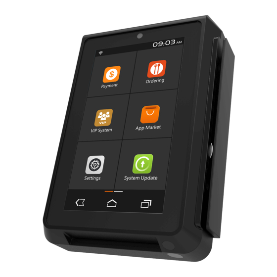
Page 19: Touchscreen
2.2.5 Touchscreen The IM30 has a 5" LCD capacitive touchscreen located on its front face. Figure 18: touchscreen (outlined in blue hatch) This display has a resolution of 1280 x 720 pixels and is equipped with an adjustable LED backlight. This touchscreen functions as the primary user interface for the device as well as the primary mechanism for the device to display information to users. -
Page 20: Front Facing Camera
Figure 19: front facing camera (in blue) This 2 megapixel (1616 x 1232) camera is capable of capturing video or photos of anything facing the front of the IM30 unit. Its primary purpose is for facial recognition in localities where such a function would be useful. -
Page 21: Code Scanning Camera
Figure 20: code scanning camera and position indicator LED (in blue and green respectively) This 0.3 megapixel (648 x 488) camera located near the bottom of the IM30 is designed to read common 1D or 2D codes (such as barcodes and QR codes). The camera is paired with a position indicator LED that allows users to orient their coupons, cards, or mobile devices so that the code is positioned at the optimal location and distance when the light from the LED directly illuminates the code. -
Page 22: Magnetic Strip Card Reader
2.2.8 Magnetic Strip Card Reader The IM30 has a magnetic strip card reader located on right hand side of the device. Figure 21: magnetic strip card reader (outlined in blue) Magnetic Strip Card Reader triple track reading bidirectional reading ... -
Page 23: Smart Card Reader
2.2.9 Smart Card Reader The IM30 has a magnetic smart card reader located on bottom side of the device. Figure 22: smart card reader (outlined in blue) Smart Card Reader reads 1.8V, 3V and 5V synchronous and asynchronous cards ... -
Page 24: Contactless Card Reader
2.2.10 Contactless Card Reader The IM30 has a contactless card reader with an RF antenna located on its front face. The read area for this card reader roughly corresponds to the top half of the touchscreen on the front of the device. -
Page 25: Proximity Detector
2.2.11 Proximity Detector The IM30 has a optical proximity detector located near the lower right side of its front face. Figure 24: proximity detector (optical emitter in blue, receiver in green) The proximity sensor detects light in the visible spectrum and is tuned to detect objects within 5 to 8 cm of the sensor. -
Page 26: Led Status Indicator
2.2.12 LED Status Indicator The IM30 has a RGB status indicator LED located near the lower right side of its front face near the proximity detector. Figure 25: LED status indicator (highlighted in blue) The operation of the LED status indicator is software controlled and depends on the specific configuration of the device. -
Page 27: Product Installation
3.1 Device Dimensions The IM30 has the physical dimensions shown in Figure 26. Note that various cables plug directly into the back of the device, so greater clearance than shown for the back end of the device is needed to properly install an IM30 unit. -
Page 28: Mounting Bracket
3.2 Mounting Bracket The IM30 is equipped with a plastic mounting bracket that allows it to be fixed into place on a mounting plate. Figure 27: mounting bracket (outward oriented face) PAX TECHNOLOGY LIMITED Page 28 of 35 Product Manual... -
Page 29: Mounting Plate Dimension
Figure 28: mounting bracket dimensions 3.3 Mounting Plate Dimension The IM30 is designed to be mounted on vertical surfaces through a mounting plate. Figure 29: mounting plate dimensions (mm) These dimensions are those of a standard door module as defined by the European Vending Association. -
Page 30: Device Installation
Installing the mounting bracket The first step to installing the IM30 as part of an unattended payment terminal is to secure the mounting bracket onto the mounting plate. The back of the mounting plate should have four M4 stud bolts that correspond to the four outer mounting points on the mounting bracket. -
Page 31: Figure 30: Attaching The Mounting Bracket To The Mounting Plate
Installing the IM30 unit After the mounting bracket is secured to the mounting plate, insert the IM30 unit through the front of the mounting plate into the mounting bracket. Then apply a torque of 1.2 ± 0.2 Nm to the four M4 screws to secure the IM30 to the mounting bracket through its four inner mounting points. -
Page 32: Figure 31: Inserting The Im30 Unit Into The Front Of The Mounting Plate
Figure 31: inserting the IM30 unit into the front of the mounting plate Figure 32: securing the IM30 unit in place with the four M4 screws PAX TECHNOLOGY LIMITED Page 32 of 35 Product Manual... -
Page 33: Product Services
If none of the above steps resolve the problem, contact an agent from your local vendor to repair the device. PAX TECHNOLOGY LIMITED Page 33 of 35 Product Manual... - Page 34 Also make sure that the cable used follows USB specifications, attempt to use another cable if possible. Check to see if the USB drivers are present and up to date. PAX TECHNOLOGY LIMITED Page 34 of 35...
- Page 35 Q: What should I do if there are errors while using the USB port? A: Use the USB cable packaged with the IM30 unit instead of a third party cable. Do not use an USB hub, directly attach the cable to whatever device is being linked.
Need help?
Do you have a question about the IM30 and is the answer not in the manual?
Questions and answers