
Related Manuals for REPLIGEN Konduit


Summary of Contents for REPLIGEN Konduit
- Page 1 Konduit User Guide repligen.com © 2024 Repligen Corporation. All rights reserved. The trademarks mentioned herein are the property of Repligen Corporation and/or its affiliate(s) or their respective owners.
- Page 2 Product are expressly disclaimed. Customer shall refer to the terms and conditions of sale governing the transaction for any and all warranties for the Product. Repligen Corporation shall not be liable for errors contained herein or for incidental or consequential damages in connection with the furnishing, performance, or use of this material.
-
Page 3: Table Of Contents
Table 7. Specifications ....................................8 Table 8. Placement of Inline Sensors ................................ 9 List of Figures Figure 1. Back of Konduit ..................................8 Figure 2. Installation of Tubing in ABV ..............................9 Figure 3. Front of Konduit; UV, Cond/Temp Ports ..........................10... - Page 4 Konduit User Guide Abbreviations absorbance ampere Absorbance Unit Celsius Conformité Européenne centimeter Cond conductivity diafiltration volume Electromagnetic Compatibility European Union height hertz kilogram length milliampere millisiemens nanometers personal protective equipment pounds per square inch Temp temperature tangential flow filtration UF/DF...
-
Page 5: Table 1. Konduit Capabilities
UV photometer is optional. For the latest version of the document, please visit repligen.com. It is highly recommended that the installation process be executed by a trained Repligen engineer. For further support with troubleshooting or process optimization, please contact your local Repligen Field Application Scientist. -
Page 6: Table 3. Safety Precautions
General requirements 3. Product Description The base unit of Konduit integrates conductivity, temperature, UV monitoring, and automation functionalities into the KrosFlo KR2i and KMPi Tangential flow filtration (TFF) Systems. Included are two combination conductivity/temperature inputs, two UV inputs, and a power supply. -
Page 7: Table 5. Monitoring Ranges
Conductivity 0.1 – 100 mS/cm Temperature 2°C – 50°C Table 6. Part Numbers Part Number Component ACCD-BR KONDUiT Base Unit - rebranded ACCD-U280 UV Photometer 280nm ACCD-U260 UV Photometer 260nm ACCS-18HB CONDUCTIVITY SENSOR PACKAGING 1/8" HB ACCS-14HB Conductivity Sensor, Single-use, non-sterile, PS, 1/4" HB ACCS-12HB Conductivity Sensor, Single-use, non-sterile, PS, 1/2"... -
Page 8: Table 7. Specifications
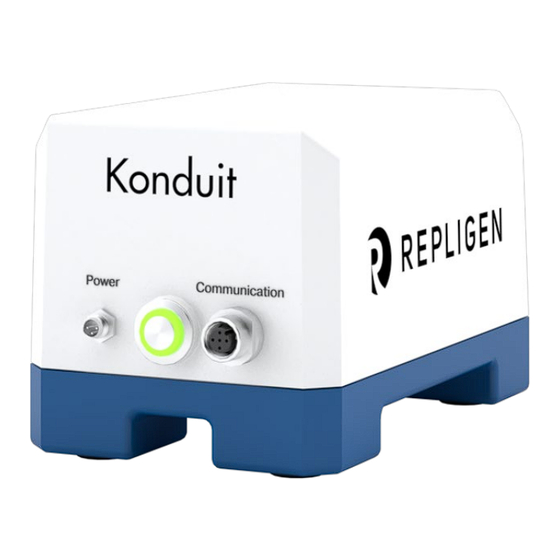
1. With TFF System powered on, connect Konduit communication cable either to the KR2i auxiliary octopus cable or to a null modem cable that is then connected to Valve 2 on the KMPi octopus cable. 2. Connect the power cable to the power port. A green light on the On/Off button indicates that Konduit is receiving power (Figure Figure 1. -
Page 9: Table 8. Placement Of Inline Sensors
Konduit User Guide Table 8. Placement of Inline Sensors Sensor Placement Notes concentration permeate fill with starting buffer Conductivity/Temperature diafiltration recirculation fill with DF buffer alarm permeate detects breakthrough concentration recirculation endpoint > starting point diafiltration permeate endpoint < starting point Fill sensor with buffer and press "tare"... - Page 10 8. Launch KF Comm 2 Data Collection workbook for TFF System. Note: Konduit can be placed behind the KR2i or KMPi System. No physical buttons or interfaces are on the base unit. The UV photometer has a tare button that needs to be accessible. Cables can be placed in the cable boxes provided with the KR2i or KMPi Systems.
- Page 11 1. For Konduit operation with KF Com 2 or 2C software, please refer to Repligen document UG-3116: KFComm2 Software, User Guide. 2. Power on the TFF System, then connect Konduit to the TFF System and power port. Wait at least one minute for Konduit to establish connection with the TFF System.
- Page 12 9. OPTIONAL: If using a UV photometer, a note should be placed, for reference only, in the header section of the Data Collection workbook indicating a wavelength of 260 or 280 nm. Note: To create a recipe with flow totalizer the user must set the Konduit Channel 1 to auxiliary and the type to flowmeter. 5.2 Software Operation (KF Comm 1) 1.
- Page 13 © 2024 Repligen Corporation. All rights reserved. The trademarks mentioned herein are the property of Repligen Corporation and/or its affiliate(s) or their respective owners. Document Number:[Document::Prefix]-[Document::Number] Revision: [Document::Version] Effective Date: [Document::PublishDate] Legacy Document #: [Metadata::Legacy document number] Page 13 of 13...
Need help?
Do you have a question about the Konduit and is the answer not in the manual?
Questions and answers