
Subscribe to Our Youtube Channel
Related Manuals for REPLIGEN Spectrum KR2i


Summary of Contents for REPLIGEN Spectrum KR2i
- Page 1 Spectrum® KR2i / KMPi TFF Systems USER GUIDE AND OPERATING INSTRUCTIONS Spectrum® KrosFlo® Research 2i TFF System Spectrum® KrosFlo® MiniKros Pilot i TFF System...
- Page 2 The information contained in this document is subject to change without notice. Repligen Corporation makes no warranty of any kind with regard to this material, including, but not limited to, the implied warranties of merchantability and fitness for a particular purpose.
-
Page 3: Table Of Contents
Table of Contents Introduction ......................... 6 Safety Precautions ........................ 7 Explanation of Symbols: ........................7 WARNING: Product Use Limitation ....................8 Specifications ........................8 KR2i Specifications ..........................8 KMPi Specifications ..........................9 KONDUiT Specifications ........................10 System Configuration and Major Components ..............12 4.1 Pump Drive, Pump Head, &... - Page 4 8.2 Detailed Pump Mode Operation ....................40 8.2.1 Concentration Mode ..................... 40 8.2.2 Concentration/Diafiltration Mode ................41 8.2.3 Concentration 1/Diafiltration/Concentration 2 Mode ..........43 8.2.4 Concentration 1/Diafiltration 1/Diafiltration 2/Concentration 2 Mode ....... 44 8.2.5 Constant Feed Concentration Mode ................45 8.2.6 Constant Feed/Diafiltration/Concentration Mode ............
- Page 5 11.6 Worksheets Overview ......................73 Basic Concepts of Tangential Flow Filtration ................ 74 12.1 Introduction ..........................74 12.2 Concentration .......................... 74 12.3 Diafiltration ..........................75 Troubleshooting ......................... 75 Replacement and Auxiliary Parts ..................76 Index ..........................77...
-
Page 6: Introduction
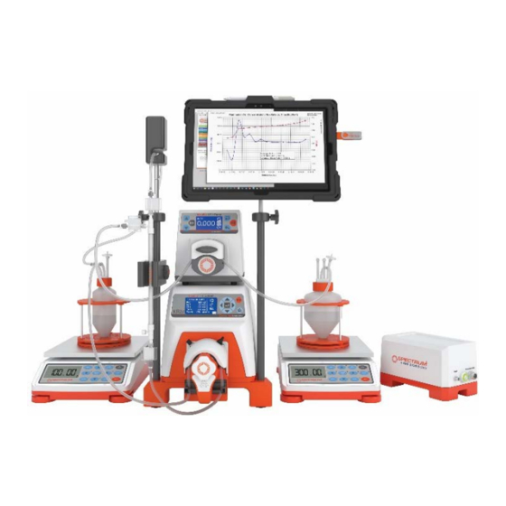
KR2i / KMPi TFF Systems Introduction Introduction The KR2i [KrosFlo® Research 2 integrated] and KMPi [KrosFlo® MiniKros® Pilot integrated] Tangential Flow Filtration (TFF) Systems are ideal automated pump systems for processes ranging from 1ml to 10L and 0.5L to 500L respectively. The systems consist of a digital peristaltic pump, man/machine interface with graphical LCD display, Pump Head, digital readouts of pressure values with automated shut-off controls, module stand, and real-time data collection software KF Comm. -
Page 7: Safety Precautions
KR2i / KMPi TFF Systems Safety Precautions • Direct and easy scale-up for production volumes Safety Precautions DANGER: High voltages exist and are accessible. Use extreme caution when servicing internal components. Remove power from the pump before any cleaning operation is started. WARNING Remove power from the pump before attempting any maintenance. -
Page 8: Warning: Product Use Limitation
KR2i / KMPi TFF Systems Specifications WARNING: Product Use Limitation Risk of Danger. Consult Operating Instructions for nature of hazard and corrective actions. This product is not designed for, nor intended for use in patient connected applications; including, but not limited to, medical and dental use, and accordingly has not been submitted for FDA approval. -
Page 9: Kmpi Specifications
KR2i / KMPi TFF Systems Specifications Temperature, Operating: 0° to 40°C (32° to 104°F) Temperature, Storage: –25° to 65°C (–13° to 149°F) Humidity (non-condensing): 10% to 90% Altitude: Less than 2000 m Pollution Degree: Pollution Degree 2 Compliance: (For ETL Mark): UL 61010-1, CAN/CSA C22.2 No. -
Page 10: Konduit Specifications
KR2i / KMPi TFF Systems Specifications All models Current input (0-20 mA or 4-20 mA @ 250 Ω), ±50V common mode range Construction Dimensions (L × W × H): 17.5 in × 11 in × 13 in (445 × 280 × 330 mm) Weight: 40 lb (18 kg) Enclosure Rating:... - Page 11 KR2i / KMPi TFF Systems Specifications b. Input Frequency: 47-63 Hz c. Input Current: ~0.4A KONDUiT Power Requirements a. Voltage: 24 VDC b. Current: 0.625 A Environment Temperature, Operating: 2°C to 50°C Temperature, Storage: -25°C to 65°C Chemical Resistance: Powder-coated aluminum, urethane Pressure Range: Rated for pressure up to 75 psi (5 bar) Readability Conductivity...
-
Page 12: System Configuration And Major Components
KR2i / KMPi TFF Systems System Configuration and Major Components a later version of the same standard incorporating the same level of testing requirements. (For CE Mark): EN61010-1: (EU Low Voltage Directive) and EN61326: (EU EMC Directive) System Configuration and Major Components Pump Drive, Pump Head, &... -
Page 13: Materials Of Construction
KR2i / KMPi TFF Systems Materials of Construction System Parts List: Part Description Quantity KMPi Pump Drive w/ Integrated Pressure Monitor Auxiliary Component Octopus Cable Pressure Transducer Octopus Cable Power Supply Cable KMPi 13LPM Easy-Load Pump Head KMPi Fittings Kit KrosFlo Module Accessory Kit SAW Scale 12"... - Page 14 KR2i / KMPi TFF Systems Setup and Operation 4. Connect one (if using KR2i) or up to two (if using KMPi) Automatic Backpressure Valves (ABV's) to the Auxiliary Component Octopus Cable's "Valve 1" ("Valve" for KR2i) and/or "Valve 2" (see Section 10.3 for ABV Setup details) 5.
-
Page 15: Manual Mode Setup
KR2i / KMPi TFF Systems Setup and Operation Manual Mode Setup NOTE: Valves are intentionally left out of the diagrams below for visual clarity. Diafiltration Buffer Reservoir Module Feed Reservoir Permeate Reservoir Permeate Pump Diafiltration Pump Feed Scale KMPi Pump Permeate Scale (Auxiliary Pump 2) (Auxiliary Pump 1) -
Page 16: Mode Setup
KR2i / KMPi TFF Systems Setup and Operation C. Mode Setup Module Permeate Reservoir Feed Reservoir KMPi Pump Permeate Scale 1. Auxiliary Pumps a. (Optional) To control permeate rate, connect auxiliary pump to the Auxiliary Component Cable’s “Auxiliary Pump 2” port b. -
Page 17: C/D/D/C Mode Setup
KR2i / KMPi TFF Systems Setup and Operation a. Connect auxiliary pump to the Auxiliary Component Cable’s “Auxiliary Pump 1” port and second auxiliary pump to the Auxiliary Component Cable's "Auxiliary Pump 2" port b. Connect Auxiliary pump power cables(s) 2. -
Page 18: Cfc Mode Setup
KR2i / KMPi TFF Systems Setup and Operation CFC Mode Setup NOTE: Permeate Pump is optional and shown in the diagram as an example for applications that require permeate control. Extra Feed Reservoir Module Feed Reservoir Permeate Reservoir Permeate Scale Diafiltration Pump KMPi Pump Permeate Pump... -
Page 19: Cf/D/C Mode Setup
KR2i / KMPi TFF Systems Setup and Operation CF/D/C Mode Setup Module Feed Reservoir Permeate Reservoir KMPi Pump Permeate Scale Constant Feed Pump Feed Scale (Auxiliary Pump 1) Extra Feed Reservoir Diafiltration Buffer Reservoir Diafiltration Pump (Auxiliary Pump 2) 1. Auxiliary Pumps a. -
Page 20: Ctrl Mode
KR2i / KMPi TFF Systems Setup and Operation Ctrl Mode NOTE: Refer to section 8.2.1.7 and 8.3 for further information about Ctrl Mode. Diafiltration Buffer Reservoir Module Feed Reservoir Permeate Reservoir Feed Scale KMPi Pump Permeate Pump Permeate Scale (Auxiliary Pump) 1. - Page 21 KR2i / KMPi TFF Systems Setup and Operation Figure 1A: Modify Set-Points view of Pump Control Records process time once pump After ”Start” is pressed, the Gear icons bring Visible but disabled starts. Does not record when step that the Pump Mode is up mini menus for when the valve is not pump is paused, and resets when...
- Page 22 KR2i / KMPi TFF Systems Setup and Operation Figure 1B: Overview view of Pump Control Switches to “Set Points” view. Similar to the Progress Bar, the live value’s position (as While Function runs, the process bar fills up to show indicated by a thick grey slightly longer line) on the alarm...
-
Page 23: Entering System Settings
KR2i / KMPi TFF Systems Setup and Operation Status Bar: Upper portion of Pump Control that allows user to view elapsed running time and current Pump Mode. The user can also Start/Pause/Stop the Pump, and Open all Valves from the Status Bar. - Page 24 KR2i / KMPi TFF Systems Setup and Operation 1. Main Pump Tubing Size: Select the tubing size used through the pump head. Standard Masterflex® tubing sizes for both the KR2i and KMPi sized pumps are used. Ramp Rate: Enter the ramp rate of the recirculation pump up to 15 sec. Slow for Valve: If turned on the system will automatically reduce the pump speed when pressure buildup continues to increase and the valve is fully open.
- Page 25 KR2i / KMPi TFF Systems Setup and Operation 3. Pressure/Valve Pressure Unit: Either psi or bar NOTE: Green highlighted boxes are currently selected. Valve: Enter both Valve 1 and Valve 2 (for KMPi) settings. Valve Mode: Select to control Valve Manually or Automatically (see section 10.3.3). Tubing Size: Select the tubing size that goes through the backpressure valve.
- Page 26 KR2i / KMPi TFF Systems Setup and Operation 4. Alarms Silent Alarm: Turn on to silence the alarm inside the pump console. PC Silent Alarm: Turn on silence the alarm from the PC; Test confirms the PC alarm is working. Pressure and Scale: Activate and input the setpoint for the various warnings and interlocks.
- Page 27 KR2i / KMPi TFF Systems Setup and Operation 5. Hardware Setup Settings for the Automation Modes and general system parameters are entered into the Hardware Setup window. NOTE: All hardware settings and other options can be entered in the system console under the wrench icon.
- Page 28 KR2i / KMPi TFF Systems Setup and Operation Scale Required for Manual: Manual Mode will not start unless both Feed and Permeate Scales are present. Valve 2 (For KMPi Only): Select either if Valve 2 port is being used with Automatic backpressure valve or with KONDUiT Diafiltration and Concentration 1 and 2: Select the control mechanism for the automated mode setpoints.
- Page 29 KR2i / KMPi TFF Systems Setup and Operation Diafiltration 2 Set Point (Diaf 2 used in CDDC mode for second wash buffer): 1. DV (Diafiltration Volumes) a. End-point control when permeate scale reaches target DV based on weight of feed scale and holdup loop b.
-
Page 30: Using Pump Interface
KR2i / KMPi TFF Systems Setup and Operation a. End-point control when retentate and permeate scale reaches target CF based on weight of feed scale and holdup loop b. Example Application: concentration of virus or protein 2. UV a. Semi-quantitative end-point control when UV reaches target AU; Application dependent, offline confirmation needed for verification b. -
Page 31: Main Screen
KR2i / KMPi TFF Systems Setup and Operation b. Directional Arrows – Navigate throughout menu items by highlighting with directional arrows c. Enter – Select highlighted menu items and input information d. Start/Pause – Start/Pause main pump from any menu e. -
Page 32: Remote Control Of Auxiliary Pumps And Valves
KR2i / KMPi TFF Systems Setup and Operation Feed Flow Rate – Main drive’s flow rate g. Pump Mode Resume Icon – When a Pump Mode other than Manual Mode is paused with the Start/Pause key, the Pump Mode can be resumed by pressing the Enter key while highlighting the Pump Mode Resume icon. - Page 33 KR2i / KMPi TFF Systems Setup and Operation Pump 1 Captured Pump 1 Released Pump 1 Running, Animated Press the Enter key on a highlighted Control Icon to set the flow rate of the selected pump in ml/min using the Directional Arrow soft buttons Press Enter again to exit the Auxiliary Pump flow rate screen When a Pump Mode is not running, the user may release and capture control of the Auxiliary Pumps...
- Page 34 KR2i / KMPi TFF Systems Setup and Operation Valve Control Icons When on the upper half of the main screen's side bar and one (for the KR2i) or two (for the KMPi) Automatic Backpressure Valves (style of valve-- SmartValve or Classic-- does not matter, however box-style Automatic Backpressure Valve must be from 2015 or newer) connected, one (for the KR2i) or two (for the KMPi) valve icons with the numbers "1"...
-
Page 35: System Settings
KR2i / KMPi TFF Systems Setup and Operation 7.10.4 System Settings a. Pump Mode – Depending on user’s Auxiliary Components, user may select one of many Pump Modes for the TFF system to operate in that allow for manual, semi-automated, and automated processes b. - Page 36 KR2i / KMPi TFF Systems Setup and Operation g. PSI Decimals – For PSI unit of measure only—select preferred number of PSI decimals (range of 0, 1, and 2) h. Bar Decimals – For BAR unit of measure only—select preferred number of BAR decimals (range of 1, 2, and 3) Key Timeout –...
-
Page 37: Pressure Calibrate
KR2i / KMPi TFF Systems Setup and Operation 7.11 Pressure Calibrate 1. Ensure proper connection between a set of new pressure transducers and Octopus Cable ports, then tare pressure readings 2. Turn on positive air source from a calibrated pressure source and adjust to dispense 5 psi / 0.35 bar of pressure, then turn positive air source off 3. -
Page 38: Tubing Calibration
KR2i / KMPi TFF Systems Setup and Operation e. Pp Lo Alarm – When Permeate Pressure (Pp) value ≤ Pp Lo Alarm value, the pump drive will alarm but continue running Pp Lo Stop – When Pp value ≤ Pp Lo Stop value, the pump drive will stop running g. -
Page 39: System Functionality
KR2i / KMPi TFF Systems System Functionality 5. Use directional keys to correct the volume on the flashing display 6. Press the Enter key to save the calibration setting. Once calibrated, a lower case "c" appears next to the tubing (e.g. 73c) 7. -
Page 40: Detailed Pump Mode Operation
KR2i / KMPi TFF Systems System Functionality h. Valve 2: Control TMP, Retentate, Inlet or Permeate Pressure KONDUiT: If Concentration or Diafiltration Set-point in Hardware Setup is set to Conductivity or UV set-points, then KONDUiT signals when pump mode ends Detailed Pump Mode Operation 8.2.1 Concentration Mode... -
Page 41: Concentration/Diafiltration Mode
KR2i / KMPi TFF Systems System Functionality 8.2.2 Concentration/Diafiltration Mode Diafiltration Buffer Reservoir Extra Feed Reservoir Module Feed Reservoir Permeate Reservoir Feed Scale KMPi Pump Permeate Scale Diafiltration Pump Permeate Pump (Auxiliary Pump 1) (Auxiliary Pump 2) C/D Mode may be used for a Fed-Batch concentration, followed by a Diafiltration. NOTE: This constant feed concentration followed by a diafiltration can be done with the CDDC mode when 2 auxiliary pumps are available (see Section 8.2.4 below). - Page 42 KR2i / KMPi TFF Systems System Functionality 2. Retentate Line from filter 3. Buffer Line 4. Vent Line 1. Feed Line to filter On both the Extra Feed Reservoir and Diafiltration Buffer Reservoir, install a vent. Ensure that Auxiliary Pump 1’s head is closed on the tubing between the Diafiltration Buffer and Feed Reservoir. The result of the setup is that the vacuum will pull the entirety of the Extra Feed Reservoir’s contents as volume is depleted from the Process Reservoir the C function of C/D Mode.
-
Page 43: Concentration 1/Diafiltration/Concentration 2 Mode
KR2i / KMPi TFF Systems System Functionality 8.2.3 Concentration 1/Diafiltration/Concentration 2 Mode C/D/C Mode may be used to further concentrate the process solution after Diafiltration. Diafiltration Buffer Reservoir Module Feed Reservoir Permeate Reservoir Diafiltration Pump Feed Scale KMPi Pump Permeate Pump Permeate Scale (Auxiliary Pump 1) (Auxiliary Pump 2) -
Page 44: Concentration 1/Diafiltration 1/Diafiltration 2/Concentration 2 Mode
KR2i / KMPi TFF Systems System Functionality 8.2.4 Concentration 1/Diafiltration 1/Diafiltration 2/Concentration 2 Mode C/D/D/C Mode may be used to wash the solution with two different buffers. Diafiltration Buffer Reservoir 1 Module Diafiltration Buffer Reservoir 1 Feed Reservoir Permeate Reservoir Diafiltration Pump KMPi Pump Feed Scale... -
Page 45: Constant Feed Concentration Mode
KR2i / KMPi TFF Systems System Functionality 8.2.5 Constant Feed Concentration Mode C/F/C Mode may be used to concentrate a sample that does not fit into the process reservoir. Extra Feed Reservoir Module Feed Reservoir Permeate Reservoir KMPi Pump Feed Scale Constant Feed Pump Permeate Pump Permeate Scale... -
Page 46: Constant Feed/Diafiltration/Concentration Mode
KR2i / KMPi TFF Systems System Functionality 8.2.6 Constant Feed/Diafiltration/Concentration Mode CF/D/C Mode may be used to further concentrate the process solution after Diafiltration. Module Feed Reservoir Permeate Reservoir KMPi Pump Permeate Scale Constant Feed Pump Feed Scale (Auxiliary Pump 1) Extra Feed Reservoir Diafiltration Buffer Reservoir Diafiltration Pump... -
Page 47: Ctrl Mode
KR2i / KMPi TFF Systems System Functionality 8.2.7 Ctrl Mode Ctrl Mode is used when no Aux Pump 1 is available and additional buffer or sample is pulled into the sealed process reservoir by vacuum. Please refer to section 8.2.2 how to setup the reservoir to pull the vacuum. -
Page 48: Running The Tff System
KR2i / KMPi TFF Systems System Functionality NOTE: In CFC and CF/D/C mode, there is a Constant Feed Concentration step (the name "CFC" is shortened to "CF" due to character constraints for "CF/D/C" mode). The CFC function is a modified Concentration function. During the CFC step of the two Pump Modes, Auxiliary Pump 1 is used as a Constant Feed Pump that pumps Extra Feed Volume from the Extra Feed Reservoir to the Feed Reservoir. -
Page 49: Pump Head Setup And Operation
KR2i / KMPi TFF Systems Pump Head Setup and Operation a. Manual Mode/Before Running Pump Mode: First Line: Current Feed Scale weight (preceded by “F:”) ii. Second Line: Current Permeate Scale weight (preceded by “P:”) NOTE: If KONDUiT is present and set-points are Conductivity or UV set-points, then depending on what KONDUiT sensors are being used the lines will display current KONDUiT readings: Line 1 - Conductivity 1 Line 2 - Conductivity 2... - Page 50 KR2i / KMPi TFF Systems Pump Head Setup and Operation L/S® 18 2300 10 (0.7) 15 (1.0) 20 (510) 22 (6.7) Part Number Roller and Bearing Material Number of Rollers MasterFlex® L/S® Tubing ACR2-H4I-01N Stainless Steel L/S® 15, 24, 35, 26 Typical Flow, Pressure and Vacuum Data—3 roller pumps MasterFlex®...
- Page 51 KR2i / KMPi TFF Systems Pump Head Setup and Operation Pump Flow rates in LPM (GPM) at indicated rpm Maximum System tubing size mL per rev pressure psi (bar) 1 to 650 I/P 26 0.01 to 4.0 (0.2) (0.9) (0.002 to 1.1) 40 (2.7) I/P 73 12.3...
-
Page 52: Kr2I Pump Head Operation
KR2i / KMPi TFF Systems Pump Head Setup and Operation Operating: 7.5 in x 7.0 in x 6.0 in (191 mm x 178 mm x 152 mm) Open: 8.7 in x 7.0 in x 10.0 in (221 mm x 178 mm x 254 mm) Weight: 8 lb (3.63 kg) * As tested with NORPRENE®, PHARMED®, and TYGON®... - Page 53 KR2i / KMPi TFF Systems Pump Head Setup and Operation pump head should be tilted about 30° counterclockwise from the intended installed orientation. Press pump head firmly against the drive and rotate clockwise until no more rotation is possible (see Figure 4). The bayonet lock lever will automatically snap toward the back of the pump, locking it to the mounting plate 3.
- Page 54 KR2i / KMPi TFF Systems Pump Head Setup and Operation Occlusion Bed Tubing Retainer (one per side) Figure 7: Tubing path through pump head – during loading KR2i Multi-Channel The KrosFlo® Research II Pump Heads can be mounted in tandem (see Figures 8, 9 and 10).
-
Page 55: Kmpi Pump Head Operation
KR2i / KMPi TFF Systems Pump Head Setup and Operation Figure 10: Drive with both pump heads locked in position first pump head CAUTION: Be sure that bayonet features on back of each pump head are fully engaged with bayonet tabs on the mounting plate or adjacent pump head before operating pump drive. - Page 56 KR2i / KMPi TFF Systems Pump Head Setup and Operation Figure 1: Components of the Easy- Figure 2: Components of the High- Load Pump Head Performance Pump Head KMPi Tubing a. Ensure that KMPi is turned off b. For Easy-Load Pump Head, move KMPi Easy-Load Pump Head lever to the left to open the pump occlusion bed.
- Page 57 KR2i / KMPi TFF Systems Pump Head Setup and Operation Figure 5: Closing occlusion bed of Figure 6: Occlusion knob on top of Easy-Load Pump Head Easy-Load Pump Head KMPi Occlusion Adjustment on Easy-Load Pump Head Use knob on top of KMPi Easy-Load Pump Head to adjust occlusion to suit application. Occlusion usually does not need to be readjusted when altering tubing.
-
Page 58: Auxiliary Component Setup And Operation
Due to the high sensitivity of SAW scales, SpectrumLabs.com highly recommends reviewing all of the SAW literature prior to running the SAW scale. TFF systems are also compatible with other scales, including some Ohaus, Mettler and other manufacturers. Please contact Repligen for more information on scale compatibility. -
Page 59: Auxiliary Pumps
KR2i / KMPi TFF Systems Auxiliary Component Setup and Operation 6. STARTUP CAUTION SAW SCALE. Every time the scale is powered up, please wait at least 30 seconds before interacting with the scale. The scale has to initialize all its parameters and load the previous settings and that takes a little bit of time 7. - Page 60 KR2i / KMPi TFF Systems Auxiliary Component Setup and Operation 4. Enter Voltage Input Menu (voltmeter icon), then use the Up or Down arrows to highlight the “I” icon and press Enter to activate it 5. Remote Control On (“I” icon) NOTE: The controls below are only accessible when the auxiliary pumps are in Internal control mode.
-
Page 61: Auxiliary Pump Settings
KR2i / KMPi TFF Systems Auxiliary Component Setup and Operation 9. Use arrow key to select “VOLTAGE INPUT” and press ENTER key. Press ENTER key again and press up arrow once, then press ENTER once more. This will set “MIN.” to 0.1 VDC 10. -
Page 62: Operation
KR2i / KMPi TFF Systems Auxiliary Component Setup and Operation 10.3.2 Operation SmartValve Refer to Section 7.9.2 for operating and setting up the parameters in the Pump Control Window on the PC. Refer to Section 7.10.3 for setting up and operating the valve from the main console touch pad. -
Page 63: Installation
KR2i / KMPi TFF Systems Auxiliary Component Setup and Operation Single-use Conductivity/Temperature Flowpath Components Combination Conductivity and Temperature in-line flowpath sensors; made of Polysulfone and in assorted hosebarb sizes. Optional: UV Photometer Available in either 260 nm or 280 nm models; consists of 2 fiber optic cables, 2 optical couplers to connect to flow cell, and power supply. - Page 64 KR2i / KMPi TFF Systems Auxiliary Component Setup and Operation 3. Assemble TFF flowpath and place Conductivity/Temp and/or UV in-line sensors at the correct placement in the flowpath. Conductivity Sensor: The sensors can be placed either in the permeate line or recirculation line when used for the Diafiltration endpoint control.
-
Page 65: Software/Firmware Operation
KR2i / KMPi TFF Systems Auxiliary Component Setup and Operation 10.4.3 Software/Firmware Operation KONDUiT operates through TFF System firmware and software; please contact Repligen Customer Service to ensure latest firmware and software combination has been loaded on TFF System and PC prior to operation. -
Page 66: Firmware Operation
KR2i / KMPi TFF Systems Auxiliary Component Setup and Operation 5. On Pump Control, click on “Alarms” gear icon to bring up Alarms a. Set applicable KONDUiT UV alarms when applicable b. If no alarm desired, set alarm value to “0” to turn alarm “Off” NOTE: If user looks at Pump Control’s Process Parameter in “Overview”... - Page 67 KR2i / KMPi TFF Systems Auxiliary Component Setup and Operation 2. Use directional arrow softkeys to highlight “Wrench” icon on TFF System LCD Menu, then press Enter softkey to open Settings menu 3. Navigate to “Hardware Setup” menu a. Set “Valve 2 Port” to “KONDUiT " (for KMPi only) b.
-
Page 68: Maintenance
• Neither the name of Repligen Corporation nor the names of its contributors may be used to endorse or promote products derived from this software without specific prior written permission. -
Page 69: Installing And Updating Tff System Software And Firmware With Kf Comm Software
4. Proceed through the default installation steps. When at KF Comm Data Collection Setup's Custom Setup screen, the user may enable the installer to also install workbooks that interface with Repligen's Pressure Monitor and KMP components by clicking on the red X icon and selecting "Will be installed on local hard drive."... -
Page 70: Usb Connection
KR2i / KMPi TFF Systems KF Comm Software 6. If user desires to update TFF system firmware, please follow steps 7 through 12 7. Power on TFF system and connect it via the USB cable on Auxiliary Component Octopus Cable to the computer 8. -
Page 71: Opening And Configuring The Kf Comm Workbook Template
KR2i / KMPi TFF Systems KF Comm Software a. The TFF system connection will be read through multiple drivers in a sequence of three before it is completely installed b. The entire process may take up to ten minutes or more depending on computer 7. -
Page 72: Data Collection Tools
KR2i / KMPi TFF Systems KF Comm Software 8. From the Configure Collection menu, the user may: a. Reopen the About Control dialog b. Retrieve Interface License dialog c. Use the Control button to retrieve the Pump Control window d. Check “Always Show Control” checkbox to enable KF Comm to always load Control window e. -
Page 73: Worksheets Overview
KR2i / KMPi TFF Systems KF Comm Software d. One More Data Point: Allows the user to take a data point that was not part of the data collection intervals e. Start Collection: Starts collecting data. Please note that during data collection, KF Comm is unable to record data if the user is actively navigating through the Add-ins tab and its menus (other than the Pump Control) or if the user is inside a cell in Excel. -
Page 74: Basic Concepts Of Tangential Flow Filtration
KR2i / KMPi TFF Systems Basic Concepts of Tangential Flow Filtration Basic Concepts of Tangential Flow Filtration 12.1 Introduction Membranes use the principle of barrier separations to differentiate components based on size. Components larger than the membrane pore are quantitatively held back by the membrane while smaller components pass through the membrane structure along with the permeate. -
Page 75: Diafiltration
UV for auto modes that sample is in when starting the process. UV sensor should be zeroed with the same buffer sample is in. For further Technical Assistance please contact Repligen/Spectrum at techserviceca@repligen.com or 310-885-4600 400-12355-000 Rev. 03... -
Page 76: Replacement And Auxiliary Parts
KR2i / KMPi TFF Systems Replacement and Auxiliary Parts Replacement and Auxiliary Parts Replacement Part Part Number KR2i Pressure Sensor Octopus Cable ACR2-CPT KR2i Component Octopus Cable ACR2-CAC KMPi Pressure Sensor Octopus Cable ACM3-CPT KMPi Component Octopus Cable ACM3-CAC KMPi Tang Boot 10/pk ACM3-RTB-10N KR2i Pump Head Plate ACR2-MPL-01N... -
Page 77: Index
KR2i / KMPi TFF Systems Index Index Alarm ......................... 23, 26, 31, 37, 38, 66, 67 Aux Pump 1 ......................... 24, 45, 46, 47 Aux Pump 2 ............................24 Auxiliary Pump ..13, 14, 15, 16, 17, 18, 19, 20, 22, 24, 32, 33, 34, 39, 41, 42, 44, 45, 48, 60, 61, 72 Backpressure Valve .......................
Need help?
Do you have a question about the Spectrum KR2i and is the answer not in the manual?
Questions and answers