
Related Manuals for REPLIGEN KrosFlo KTF


Summary of Contents for REPLIGEN KrosFlo KTF
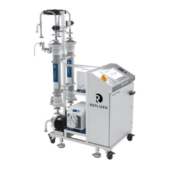
- Page 1 KrosFlo® Systems User Guide For use with: • KrosFlo® KTF Tangential Flow Filtration (TFF) System • KrosFlo® KPS Tangential Flow Filtration (TFF) System • KrosFlo® TFDF® Tangential Flow Depth Filtration (TFDF) System IF.UG.028 R1...
- Page 2 Customer shall refer to the terms and conditions of sale governing the transaction for any and all warranties for the Product. Repligen Corporation shall not be liable for errors contained herein or for incidental or consequential damages in connection with the furnishing, performance, or use of this material.
- Page 3 User Guide KrosFlo® Systems User Guide Contents 7.8.1 Warning alarms ......................20 IF.UG.028 R1...
-
Page 4: Table Of Contents
User Guide KrosFlo® Systems User Guide List of tables Table 1. Signal words, definitions and colors ..................6 Table 2. Safety symbol icons ......................7 Table 3. KrosFlo® Systems specifications ................... 9 Table 4. Input parameters for Main screen ..................15 Table 5. - Page 5 User Guide KrosFlo® Systems User Guide Abbreviations Ampere Celsius Concentration factor Centimeter Diafiltration volume Europe Fahrenheit Feet Human machine interface Kilograms TFDF Tangential Depth Filtration System Pounds Liquid-crystal display Liters per minute Meter Milliampere, or milliamp Module bag tubing Normalized Water Permeability Programmable logic controller Pounds per square inch Revolutions per minute...
-
Page 6: Table 1. Signal Words, Definitions And Colors
Other components of the system include the retentate flow meters, permeate flow meter, pressure sensors, Repligen control panel controlled by an Allen-Bradley PLC, using an iFIX-based HMI program to initiate actions, flexible tube flow path, and a Repligen stainless steel frame/cart that serve as the system support structure. -
Page 7: Table 2. Safety Symbol Icons
User Guide KrosFlo® Systems Table 2. Safety symbol icons Electrical Hazard Heavy Object Heat Hazard Radiation Hazard Crush Hazard Pinch Hazard Authorized and Qualified Inhalation Hazard Read the Manual Personnel Only Noise Level Hazard repligen.com IF.UG.028 R1... -
Page 8: Figure 1. Caution And Warning Examples
WARNING – Due to a noise level of 80 decibels or greater, ear protection is required when the System pumps are operated at a speed of greater than (>) 6000 RPM. repligen.com IF.UG.028 R1... -
Page 9: Table 3. Krosflo® Systems Specifications
Controller - Allen-Bradley PLC (Programmable Logic Controller) HMI - Allen-Bradley Integrated Panel Display Computer (Human-Machine Interface) • ProConnex® Flow Path - Designed flexible tube flow path from Repligen • • Support structure - Stainless steel filter stand and lab cart from Repligen repligen.com IF.UG.028 R1... - Page 10 (not on end fittings). Inspect the filter and pump before tightening clamps in place; there should be no strain placed upon any of the filter, pressure sensor or pump connections. repligen.com IF.UG.028 R1...
-
Page 11: Figure 2. Polysulfone Pressure Sensors Example
A ferrite bead (P/N 3000541) is provided for each flow path pressure sensor to protect it against possible electromagnetic interference (EMI). We recommend that you install the supplied ferrite bead on each flow path pressure sensor cable to provide EMI protection for the pressure sensor. repligen.com IF.UG.028 R1... -
Page 12: Figure 3. Installed Flow Path Pressure Sensor Ferrite Bead
2. Open the ferrite bead. 3. Seat the flow path pressure sensor cable in the bead. 4. Wrap the cable around the bead. 5. Snap the bead closed. repligen.com IF.UG.028 R1... - Page 13 NOTE: The BLUE Reset button on the control panel enclosure is pressed to reset the Master Control Relay at startup, power outage, or E-Stop only. All other alarm conditions are reset from the Alarms screen on PC/HMI. Be sure to exit iFix, and shutdown Windows before shutting down the KrosFlo® System. repligen.com IF.UG.028 R1...
-
Page 14: Figure 4. Main Screen Example
Setpoint data is entered by touching a BLUE input box. Type in the new Setpoint data and press ENTER (= Equal Sign) button on the pop-up keyboard. The ENTER (= Equal) button MUST be pressed after data entry or the new Setpoint value will not be stored. repligen.com IF.UG.028 R1... -
Page 15: Table 4. Input Parameters For Main Screen
Settings Screen to reset PID control parameters after the system has been stopped. This feature allows for a smoother restart of the system at auto process parameters. When the Reset Windup button is not pressed, the control loop will start at the pump speeds previously arrived at output. repligen.com IF.UG.028 R1... -
Page 16: Figure 5. Settings Screen (Fed Batch Disabled)
Press RESET PID TO FACTORY SETTINGS to return all pumps to their default PID tuning values. Press the Use Weight/Use CF toggle button to specify whether the Initial and Final Concentration setpoints are based on the specified weight (Kg) or concentration factor. repligen.com IF.UG.028 R1... -
Page 17: Figure 6. Tubing Selection Popup Screen
Feed Temp - used in calculating Normalized Water Permeability (NWP). A description of • NWP can be found in Section 12.5 at the end of this manual. Table 5 lists the ranges of values for all input parameters on the Settings screen. repligen.com IF.UG.028 R1... -
Page 18: Table 5. Input Parameters For Settings Screen
Buffer Pump (P-03) P 0 - 1000 Buffer Pump (P-03) I 0 - 1000 Buffer Pump (P-03) D 0 - 1000 Press the Exit iFix button located on the lower right corner of the Settings screen to exit the program. repligen.com IF.UG.028 R1... -
Page 19: Table 6. Alarm Setup Screen Setpoint Range
High Permeate Flow (FL-02) 0 - 20.0 Low Recirc Flow (FL-01) 0 - 85 High Recirc Flow (FL-01) 0 - 85 High Feed Tank Level (FL-01) 0 - 200 High Shear 0 - 12000 Low Shear 0 - 12000 repligen.com IF.UG.028 R1... -
Page 20: Figure 8. Alarms Screen Example
Flashing Button and Beeper will sound when Alarm setpoint is reached. The system will continue to run during Alarm conditions and indicate active alarm. Alarms can be acknowledged and cleared when Alarm Conditions are satisfied (i.e. – system operation restored within Alarm boundaries). Shutdown alarms repligen.com IF.UG.028 R1... -
Page 21: Table 7. Chart Screen Parameters
Data can be viewed on the chart in real time or reviewed from a previous time period. Some features of the chart may be customized using the chart menu. The chart menu can be accessed by placing cursor on the chart and using left double-click. repligen.com IF.UG.028 R1... -
Page 22: Figure 10. Report Screen Example
Settings screen to enable/disable the Fed Batch process. Press STOP on the Settings or Main screens to stop the running process. 9. Generating reports Click REPORT on the Settings screen to access the Report screen. Figure 10. Report screen example repligen.com IF.UG.028 R1... - Page 23 Any electrical work beyond the Electrical Installation and fuse replacement should be performed by trained personnel. WARNING – Peristaltic pumps must be turned off when replacing either tubing or pump heads to prevent crushing/pinching hazard. repligen.com IF.UG.028 R1...
-
Page 24: Table 8. System Fuses
Product Pump Head MasterFlex® FL-01 Retentate flowmeter Sonotec® FS04.210 CO.55/230 V2.0 FL-02 Permeate flowmeter/Flow converter Levitronix LFC-1C-PC PE-01/02/03 Pressure sensors Repligen ACPM-799-01N Panel: HMI/computer Allen-Bradley 6181P15C2MWX1AC Integrated Panel Display Computer Allen-Bradley 1766-L32BWA MicroLogix 1400 PE-01 to PE-03 Signal conditioner Allen-Bradley 931S-B1C6D-DC PE-01/PE-02/PE-03... -
Page 25: Table 10. Recommended Spare Parts
FU-6, PS-3 Input supply 220VAC AGC-10 10A FU-13, BPCV-01 AGC-1 1A FU-17, PS-1 Output 24VDC AGC-5 5A Repligen Fittings Kit 1 ½” Tri-clamp 1 ½” Tri-clamp gasket 1” Tri-clamp gasket Permeate tubing Retentate tubing 12.1 Accessing the Scale Settings screen The Scale Settings screen is a “hidden”... - Page 26 Membrane Recovery is defined to be the percent ratio of the initial DI water NWP (normalized water permeability) after cleaning in relationship to the primary NWP initial which was measured before the membrane contacted any process fluid. repligen.com IF.UG.028 R1...
- Page 27 Setup ........... 13, 19, 22, 25 Components ......6, 9, 10, 22, 23, 24 System overview ........... 13 Instructions for use ........10 System specifications ........9 Maintenance ..........23 Warning ........8, 10, 11, 13, 23 Note ..........13, 18, 22 repligen.com IF.UG.028 R1...
Need help?
Do you have a question about the KrosFlo KTF and is the answer not in the manual?
Questions and answers